I’ve seen several YouTube videos showing how guys have improved the air assist of their machines. Several show 2 solenoid switches for both low and high pressure air for engraving or cutting. I can certainly understand wiring to the “air” terminal on the Ruida controller will work once the machine setting has been changed to “true” and the air assist is switched on in Lightburn, for high pressure air. But, I don’t understand how wiring the second solenoid to the “status” terminal will provide low pressure air for an engraving layer when the air assist is turned off in Lightburn.
I hope this makes enough sense for someone to help me with an explanation. I can’t find a Ruida connection diagram that I can read clearly online.
Jack, I really need help. Although I have familiarity with electrical, I can’t get the low pressure switch/solenoid to operate. As it sits now, I have one lead connected between the 24 volt terminal on the controller and the switch (LED terminal). The other wire to the “Status” terminal on the controller. I have the high pressure wired the same except terminated to the "Air terminal on the controller; it works fine.
I misspoke in my earlier post. I’ll have the diodes on Monday and will put these in.
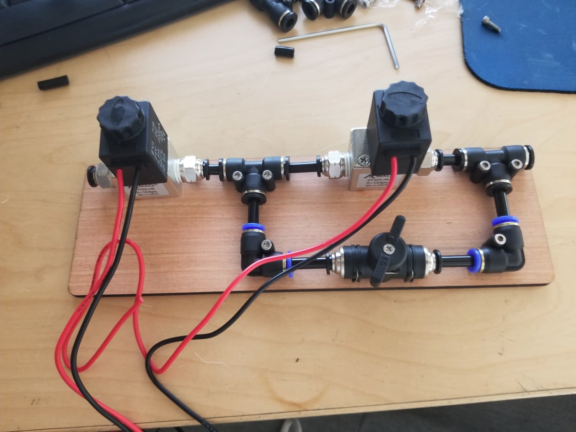
Not really a “fix” for the equipment you have already, but I use a dual port solenoid.
When enabled, the air flows from port “A” to the output. Disabled allows air from port “B” to flow. I have a manual ball valve to shut the air off when not running.
I should add that when swapping air and status connections at the controller, the LP solenoid operates, so I know it’s good. Also my controller is a KT322N
The positive side of the solenoid goes to 24V, the negative side to the Ruida Status…
When status goes low the solenoid should pick or operate… On my Ruida I can measure it. Nothing connected to status. Reading from 24V to Status, it reads 24V when active and ~0V when not active.
You could have a hardware issue… You can measure any of these outputs that sink current for a comparison… Wind, status, out1 and out2 are all the same, electrically …
I measured the voltage between 24 volt and status while the machine is running. I got ~3 volts. I changed connection to out 1 and it works, although it works regardless of weather I switch air assist off or on in Lightburn. So, when I’m engraving, I get low pressure air. When cutting, I get both LP and HP air. I recognize that this is not the way it’s supposed to work. But it is somewhat meeting the intent of what I wanted to accomplish.
Are the status lights shown in your video original or did you add these? I have none.
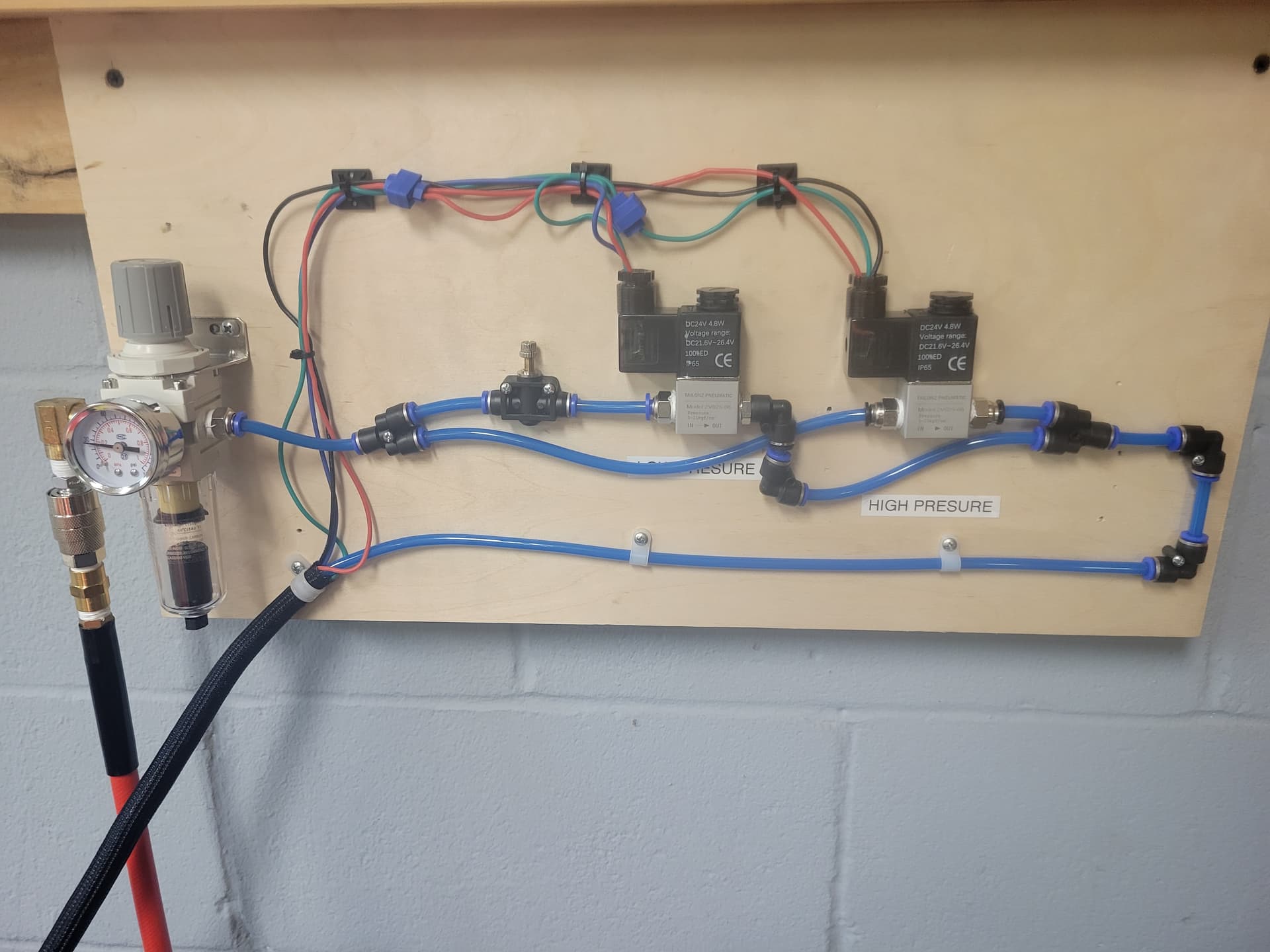
Something I just can’t figure out. Like you, I have a 2 solenoid scheme for air assist. I used red for the 24 volt positive to the KT322N. The HP solenoid is wired with the other end of the controller. The red wire is tapped to the LP solenoid. At the controller, a black wire goes to Air, then to the HP solenoid. I used a blue wire from the LP solenoid to the status terminal on the controller.
I ran a test project whose layer was fill. The air button on Lightburn was turned off, the HP solenoid activated. I changed the blue wire at the controller to Output 1, and both solenoids operated. I’ve measured voltage across the controller terminals and they reflect my test observations.
Do you think I should contact Omtech about a controller issue? I’m confident that I’ve wired correctly.
I’d guess they’d send you a whole new controller. I doubt they want you to disassemble the controller to get to it’s motherboard… but I don’t know how these companies think…
I received and installed the controller module that OMtech furnished. They included 2 files which I opened, read and write in RD Works. Their final instruction was to load from file lbset. They didn’t sent it and I assume it comes from them. Or is this file somewhere else?