Upgrading mainboard homes to wrong place

Hi, upgraded from the KT332N to the RDC6442SHB. Now the fun starts. When I turn on laser it homes to opposite locations to where I want it. As there are no limit switches at front right machine obviously crashes into that corner. Easy fix I thought, put in the Lightburn upgrade settings and reverse the limit switches if needed. Cannot do that, as without the machine on, the machine settings or the console cannot be accessed. So I thought I would swap the limit switch wiring blocks around on the main board this did not work either.

The laser is an Omtech 60w

Would be very grateful if someone can offer me a solution. TIA

Mike


I don’t have a solution for how to make the changes but if you press the escape or cancel button (I’m not near my machine to verify name) as soon as it starts moving it will stop at that location and not crash. You may need to press it a couple times. That should allow you to get into the controller software.

The home switches need to use the - axes input.

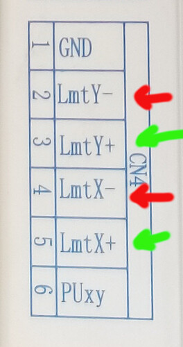
Red are home switches, green are limit switches.

Did you read the values out of the previous controller and load then into the new one?

:smile_cat:

If the machine is homing in the incorrect direction of the limit switch location. That needs to be set in the controller settings. Wire swap will not work.

Did you make a copy of the configuration from the KT332N? I believe you should be able to restore the settings to the RD6442.

It’s wired wrong…

Until it’s wired correctly, it will never work, good or bad configuration data.

That’s why I asked if he transferred that data from his old controller.

:smile_cat:

I missed it. I didn’t read past the image.

Thanks for your reply. My colours are black, blue and brown. Using the brown as ground. I have managed to get the axis to move in the correct direction but limit switches will not stop them. Tried reversing blue and black to no avail. Will carry on tomorrow and see if I can progress

Thanks Tim, that worked fine, can now alter settings

Thanks for the reply. I used the Lightburn settings for the new board

Did you read the data from the original controller and then load it into the new controller?

Since it’s wired incorrectly… it’s hard to believe it’s working and the thread is solved…?

Pressing the esc button is not a fix.

:smile_cat:

Update. The axis now home to back left, but do not stop when hitting the limit switches
I have enclosed photos showing settings and limit switch wiring

17222495395518865519413671286033|376x500


x ww

This is complicated by the fact that people ask questions trying to help you and you do not answer the question very completely or at all.

Such as – did you read the data from the previous controller and write it into the new controller?

A lot of this is different than a grbl, although the same things happen… We don’t learn by osmosis, so hang in there and ask if you don’t get it or you’ve missed somethings… it’s no crime to misunderstand one of us… Americans are good a butchering English.

Wire color means little to most of us, your home switches are unknown to us… are they NO/NC, mechanical, Hall effect or ? A photo of one of your home switches?

If you can get a number of something off the switch itself, then maybe you can find a data sheet telling you what wire color is what. This is one of my switches, a Hall effect that requires ground and power to operation and is NO, but the same type of model also has a version that puts a 5V on the line when active… There are also mechanical switch variations…

This is a Hall effect switch… it becomes active when Ferris metal come within a certain distance. It’s ID is PL-05N, you can find datasheets on these. It has the wire colors printed on it.


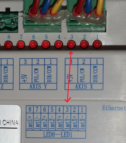
This is how the leds on the Ruida are mapped to different i/o operations.

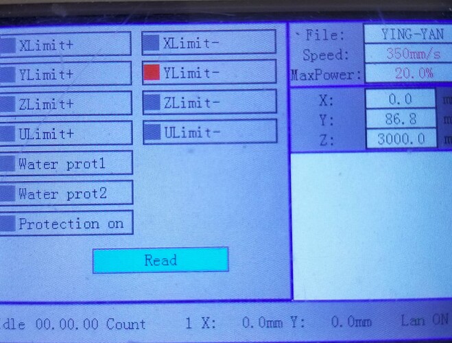
There is the also indicators in the Z/U → Diagnosis shows the active inputs. In this shot the Y home switch was active.

This short poor quality, short video shows how to check these at the controller for proper operation.

Hang in there… ask if you don’t follow what we are after …


If you don’t get the hardware correct, it will not work, not matter how much you hack the software… the hardware needs to be correct first, before you mess with any firmware or software.

It’s too bad you were lead down this firmware configuration path, I apologize for that.

I removed your solution, as I don’t think it’s solved … yet

:smile_cat:

1 Like

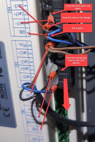
Based on the wiring of this KT332N, your switch wiring would need rearranging as follows;

After the wiring is correct you may need to also toggle the X or Y Axis setting for ‘Limiter Polarity’ in machine settings if the switch shows as always engaged in the diagnosis part of the control panel or by observing the LED lights 1 & 3 on the controller as explained above by @jkwilborn

You will also need to toggle on ‘Enable door open protect’, so the switch on the lid will be noticed.

Thank you for your in depth reply. I am pleased to say that it is all working as it should now. I would not have managed this with out the help of yourself and others who contributed, once again thank you

2 Likes

As a side note, my chiller input (wp1) showed OK on the led, but wasn’t active when I looked at the machines console… So I lost the wp1 input for the chiller.

I have never used door protect, so now it’s my chiller input… Ruida says door, but I know it’s the chiller…

Some times you need to check both the led and the diagnoses screen…

:smile_cat:

This topic was automatically closed 30 days after the last reply. New replies are no longer allowed.