Morning All i currently have a Laser Master 2 with the LU1-4 module on it. I’ve been running it for about 14 months now, and it gets pretty regular use. I have cleaned the lens a few times but it seems like i’m slowly losing engraving power, and have to increase power settings and slow the laser down in order to get the quality of engraving i require. I recently had a friend get a LM2 and it has the 24V LU2-4 head on it. Will that head work on my machine? or would i need a 24V version of the controller to make it work? Sorry not very well versed in this stuff
Assume it’s a Laser Master 2 Pro if it’s 24V system. The laser can be made to work for your laser but will not work out of the box. As you’ve discerned the voltage difference is the problem.
This is one way you could go about it. However, there’s nothing really fundamentally different in the way the controller works other than it providing 24V. So if you find a separate 24V power supply that you use to directly provide power to the laser module and send only GND and TTL/PWM signal from your controller to the laser module then this will work no problem.
If you want to avoid that entirely you could buy a different 12V module. It needn’t be from Ortur either. One thing to look out for is current requirements if you want to go to a higher power laser module. You’ll need to get a higher rated power supply for your controller in that case. And even then you might want a separate power supply to the laser module to reduce how much current is going through your controller.
Hey thanks for the quick reply it is appreciated. Its not a pro its a LM2 S2 i have the box here as i put it together for her. I should be able to rig up a direct 24V supply for the laser module (i already purchased it without thinking about the 12 vs 24 volt issue and its already shipped).
And seperate question, i have a Neje 20W module that i purchased as a back up and it came with the option for a seperate power supply, if i was to use the plug that came with it and use the power supply adapter that came in the kit i bought would that likely provide more power to the laser module that just using the jumper to run it through the current controller?
Ah… yeah, keep forgetting those exist.
The Neje 20W should have roughly the same input power requirements as the LU1-4. Assuming your power supply and controller are in good working order you’ll likely not get any difference in output power. Running a separate power supply, however, could provide some relief to the primary power supply and put less demand on your controller. Just running under lower load conditions. Could help reduce heat and lower risk of premature failure.
ok thanks, i definitely have had some challenges with focusing the NEJE, i should have just got a fixed focus instead of adjustable. I did the ramp test but still not crazy about the results. and they seem especially weak (both modules) on baltic birch plywood for some reason. have a hell of a time getting a consistent burn.
I have ordered a 24V power supply and will splice in the power on the new module showing up.
You could somewhat adapt the laser to be fixed focus… pick an ideal focus distance and spend some time to really dial in the focus. Then somehow mechanically lock the focus ring as to prevent it getting out of focus. Then you should be able to use it as if it were fixed focus.
Let us know how you carry on. There are definitely others on the forum that are curious about this.
will do, i’ve got all the parts i need, once the module arrives i’ll document with pics. and thats a good idea turning it into a fixed focus, what about using super glue once i’ve got it dialed in? with this module i’m not really interested in cutting, just engraving, i make a lot of board games so id like a dark engraving with as much speed as possible.
That could work. One danger though is that I’ve noticed with any CA glue that the offgassing actually leaves a residue or haze on materials. Would be a tragedy for that to fall on the lens. You could potentially seal the laser lens to prevent that until the glue cured. When I’ve done this in the past I found that just putting a piece of tape on the lens was sufficient to prevent movement. Granted I had put a larger focus ring on that made it easy to do so.
Have you explored pretreating wood with borax or baking soda? It can make engravings take on a very different tone and generates a very dark burn with little power. The result doesn’t seem as durable but a clear coat of some kind remedies that.
I haven’t ever tried that before, I can give it a go and see what happens. for woods like cherry, walnut, beechwood the burns are always good but with maple and even pine or baltic birch plywood i’m really disappointed with how it looks, you have to slow it waaayyyy down in order to get it decent.
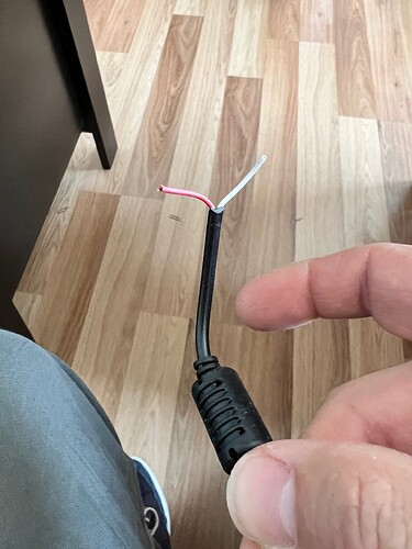
Ok, so i have received the laser, and the power supply. when i peel the power supply wires back i get a red and a white wire. I’m assuming Red is power and white is ground?
You’re talking about the wires coming out of the DC power supply? Likely red is positive and white is negative/ground. If you have a meter switch it to DC voltage and place the red lead on the red wire and the black lead on the white wire. If the voltage is positive then this is correct. If it reads negative then it’s backwards from what I said.
How does the power supply terminate? Does it go to a barrel plug? If so, there should be an indicator on the power supply if it’s center positive or center negative. Typically these are center positive. Again, can be tested with a meter with one probe placed inside the barrel very carefully to only contact the center lead and the other placed on the outer wall.
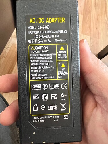
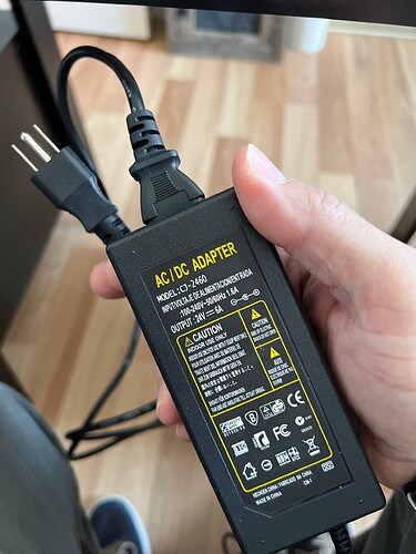
This is what it looks like.
Sorry I don’t have much knowledge on electrical stuff. I do have an amp meter that I can check it out with… should have thought of that
This picture indicates center positive.

So whatever wire goes to the center portion of the plug is positive, almost certainly the red wire. You can check for continuity if it’s not obvious. Probably easier to test for negative side.
Thanks very much! So I’m going to leave the wires for the ground and the pen alone and just cut the positive wire on the feed from the laser to the module and solder the positive wire from the power supply to it. Then clean it all up and get to burning. Will post images
Just wanted to follow-up and see if you “conversion” project succeeded or not. I ask as I may be wanting to do the same thing since I can no longer find any LU1-3 or LU1-4 lasers out there in the world (I find that odd, but maybe everyone caught onto the 24V versions and left us 12V folks in the dust and Ortur has left us hanging with no easy upgrade path other than to purchase a new machine).
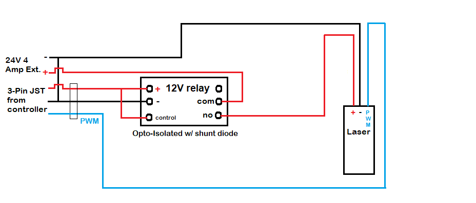
I did something similar (but not exactly) with my OLM2 Pro. I swapped out the 5.5W module with the 10W, but I wanted it to have its own separate power source. In my case (I have a 24V laser) I used a 4 amp power brick (Amazon.com: 24V DC Power Supply 4A Universal AC Adapter, 100-240 50/60Hz AC to DC 24 Volts 4Amp Power Adapter Transformer, DC 24V Power Cord, 5.5mm x 2.5mm DC Plug : Electronics) and a 24V digital relay, here’s a link to a 12V one (Relay Module with Optocoupler 1 Channel High&Low Level Relay Module Board AC 250V/10A DC 30V/10A (12V): Amazon.com: Industrial & Scientific). The output from the controller (the + and - 12V) goes to the relay, the PWM and the 24V goes to the laser (see diagram). I’ve been running with this setup for over a year now without any issues. You should be able to use something like this for your upgrade. I think, all in, I only spent $20.
EDIT: corrected error in wiring diagram to show common ground.
Can you provide a pic of what your setup looks like, more specifically what you described in your post (i.e. the laser setup)?
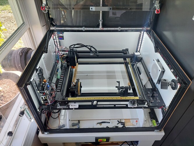
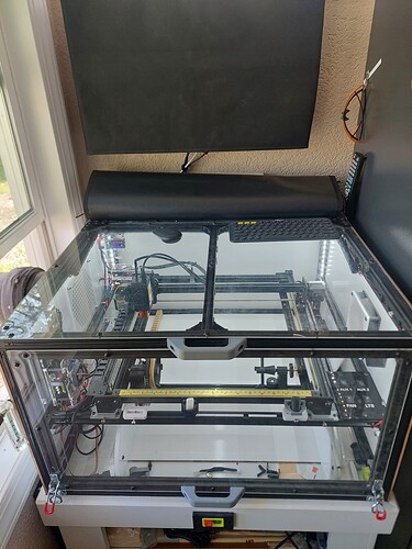
Unfortunately, it’s kind of hard to see very much from the pictures. I replaced the OEM controller on my Laser Master 2 Pro (S1) with a B-N-B 3, made by Tim Rothman. The adapter cables that came with the LU2-10A 10W were designed for the Pro S2 and were not compatible with the 3-pin JST connector that went to the 5.5W module I was replacing. The 10W laser kit has a different cabling system, as well as an OUC universal adapter box (which failed on the second day of testing).
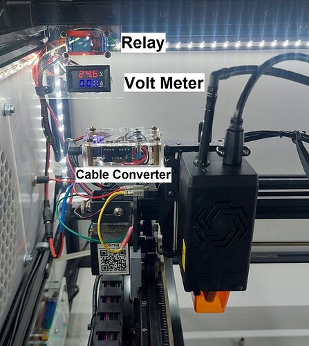
Long story short, I built my own adapter so I could hook it all up to the cabling I had. In the upper left of the picture is the relay, which switches the +24V to the laser on and off. The output from the laser controller goes to the + & - input of the relay (+12v also goes to the trigger, which is set for trigger high). PWM goes straight to the laser along with the switched 24V. In this way you can use the +12V from your controller to power a 24V laser.
Below the relay is a voltage and current meter so I can keep an eye on how much current it’s using, I have something similar on my CO2 laser. The plxy box to the left of the laser is the cable converter I made. It changes the 3-pin JST to a 6-pin PCB (along with the 24V pwr.). Both of the 24V pwr. bricks are under the enclosure. The pwr. for the laser goes to the relay and then back out thru the drag chain to the cable converter.
Ortur had an earlier version of their OUC universal adapter that would have been plug and play, but they switched to a less “universal” design. Sorry for the long reply, I hope it answers your questions. If not, let me know.
