Hello:
I have a non-linear scale problem when patterning an alignment grid on a waste board.
I am using the newest Light Burn version V1.5.01 with an extended version (400 mm x 800 mm) Ortur Laser Master Pro 2.
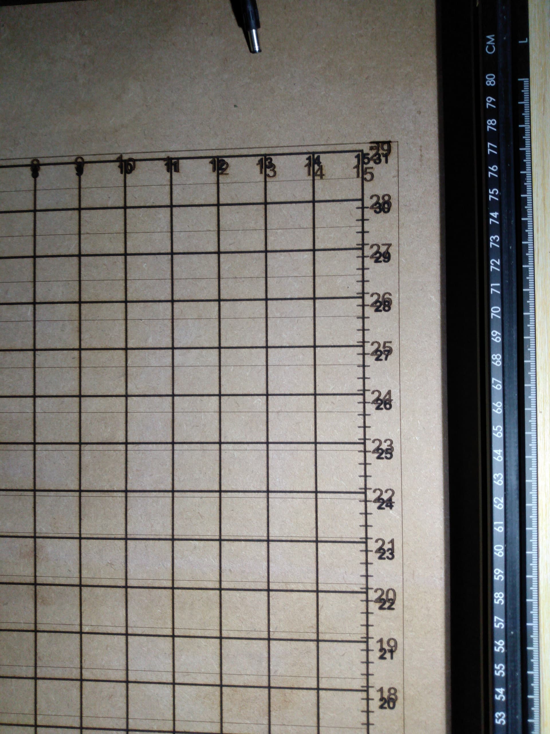
On my first grid pattern attempt, I made a 1 in grid pattern in Light Burn. The line width was narrow measuring a 7 mil in line on test burns. I offset the line on both sides, removed the reference line, and filled the offset line to make a 20 mil in line. I set the direction of the fill in Light Burn to match the horizontal and vertical directions. I was happy to see the 1 in grid was linear like the ruler I wanted it to be over 31 inches but the numbers shifted (non-linear pattern) and no longer aligned with the grid. I used a speed of 2000 mm/min and a power level of 35% using a 10W laser.
My second grid pattern used 7 mil in lines used a speed of 2000 mm/min and a power level of 35% using a 10W laser. The horizontal lines on the grid pattern tracked fine for about 400 mm and then the spacing decreased to less of an inch in a non-linear manner. The vertical lines matched the first grid pattern. The numbers in the x direction seemed like they were in the right place; the numbers in the Y direction measured linear but shifted from the line grid pattern. I was missing a horizontal border line too.
I made a test burn with a 20-mil in line grid pattern with 0.25 spaced ticks with a 9 in x 3.5 in piece of MDF. The scale was linear over the short distance and the numbers aligned to the 1 in grid pattern in. I now realized the y direction started to increase but did not see the relation till I ran the grid on the large 400 mm x 800 mm waste board.
I have seen post where the belts were not tensioned right that caused shifting of engravings. I think the using the thicker offset lines slowed down the rate of Lazer module movement to see better results. The faster moving thin lines increased the error I was seeing in the large area grid pattern. I need to keep linearity over a big area for my application and is a serious problem for me.
Do I have a belt problem? The problem isn’t Lightburn is it? Can any of you experienced laser machine operators cast some expertise on my problem? Can you give me a recommendation for a replacement 6mm, 2mm pitch synchronization belt to purchase?
Thanks for your help.
Jim
That’s a lot of words. Got any pictures for the ADD among us? ![]()
No, correct, and sure! ![]()
Whenever a diode laser’s movement does not match the commanded layout, the machine has a mechanical problem.
This mechanical checklist will generally identify the problem:
It’s written for Sculpfun machines, but you’ll recognize nearly all of the components.
The key is checking everything that contributes to lost mechanical motion:
- Belt tension, neither too tight nor too loose
- Tiny setscrews inside the belt pulleys and idlers
- Belt anchor clamps
- Frame corner bolts and brackets
- Laser head mounting screws, brackets, clamps
Everybody (myself included) starts by assuming there is only one problem, but you must methodically check everything to find them all.
If you think of the search as a treasure hunt, it becomes a lot less tedious.
Since this seems to happen near the edges (correct?), pay special attention to the wiring and associated fixings. You may be stretching or “smooshing” a flexible element

The manufacturer Ortur did not go in this detail. I did all of their checks including moving the gantry to the upper part of the machine travel and made sure the wheels touched the back end. I will re-check the mechanical assembly and the items on the check list for mechanical motion. Do use a square on each corner of the machine before tightening down the screws? What do you use for belts? Can you please provide a link for the belts used for my Ortur Laser Master 2 Pro with frame extensions (400 mm x 800 mm)? I think the belts are 6mm wide with a 2 mm pitch. Thanks for your help.
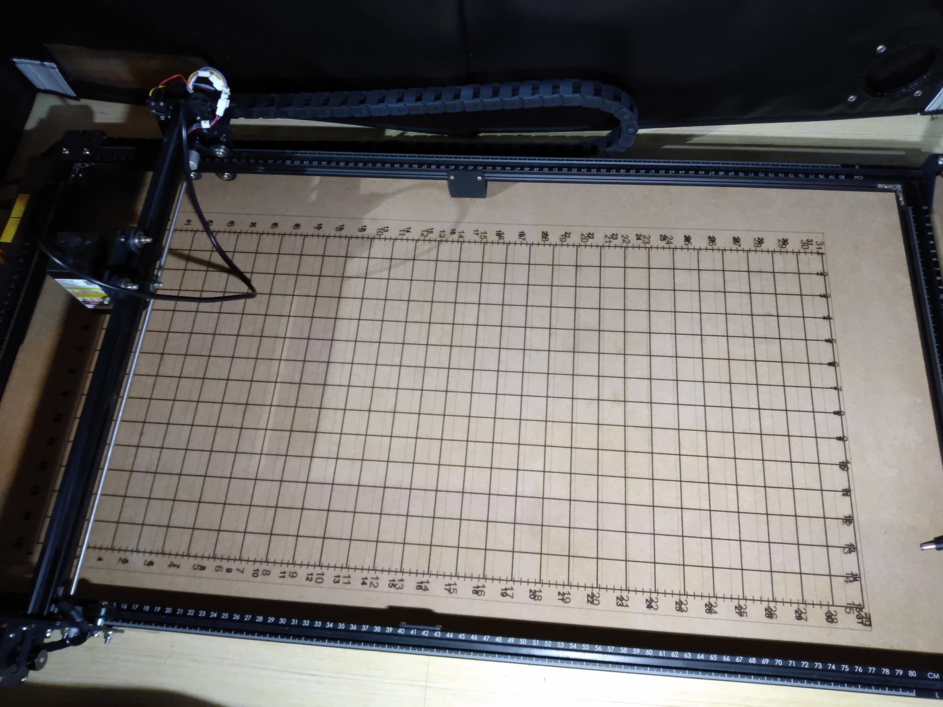
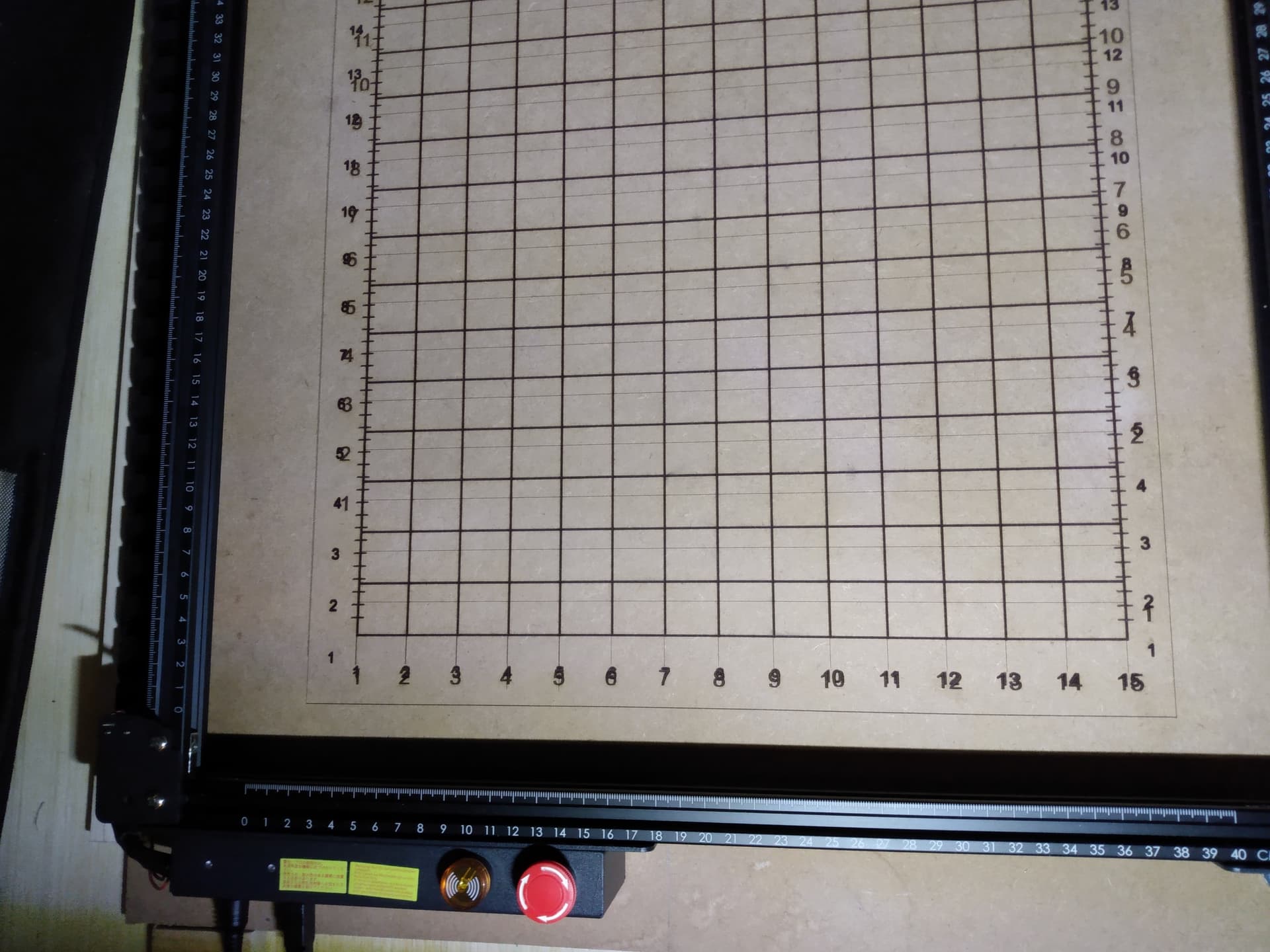
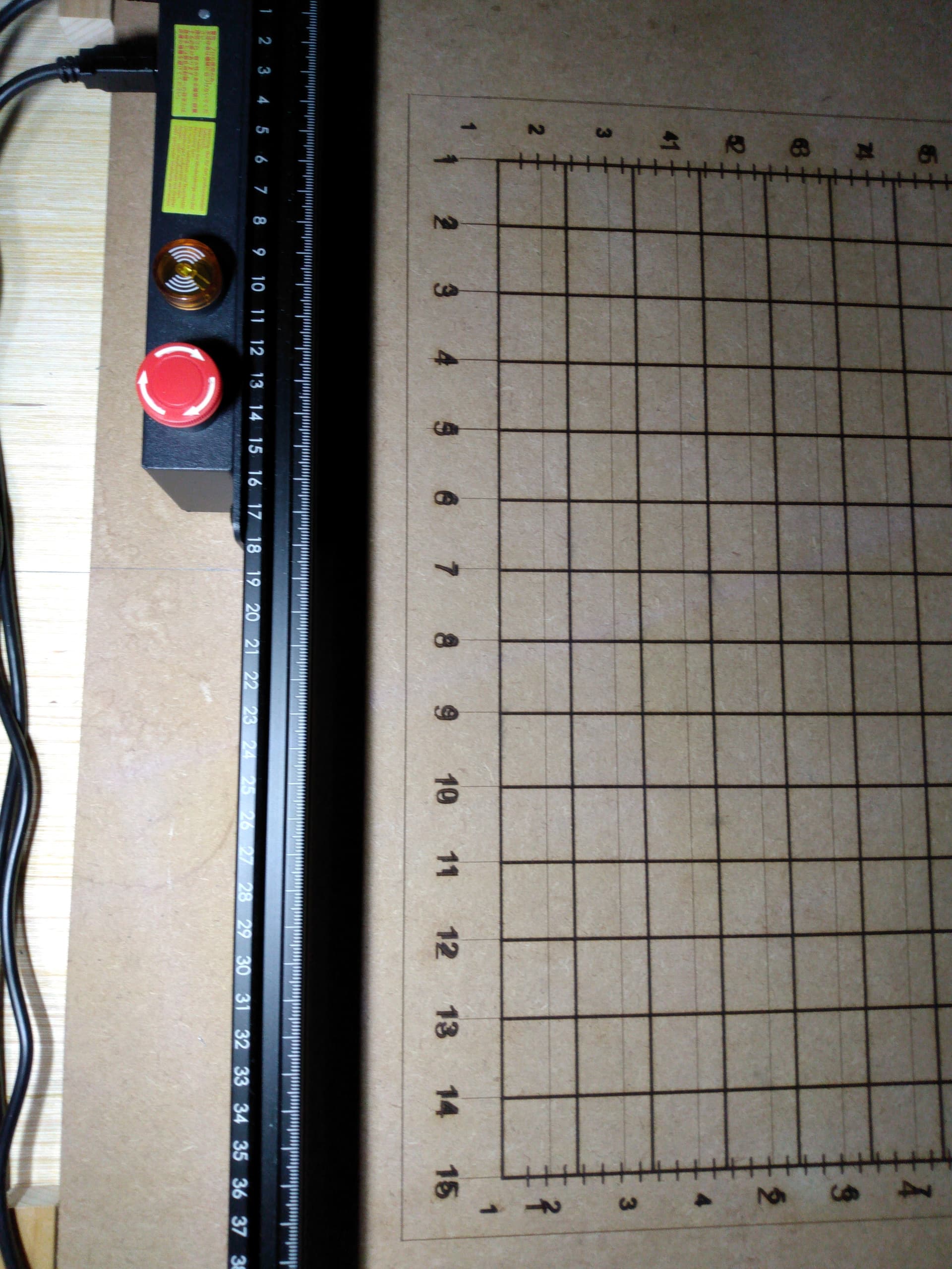
I have attached some photos for your revue. Thank you for your help. Some verbiage is in the file name of the attached pictures for description.
If this is a reasonably new machine with a new upgrade, the belts are not the problem, particularly given the photo you provided. It looks like one of the little setscrews in the pulleys has come loose; they should be snug on the flattened part of the motor shaft.
@cggorman mentions another common problem: verify that the cables are not snagging on anything or pulling taut at any point across the entire platform. With the power off, move the laser head and gantry across the platform to verify that it moves smoothly with no interference.
While you’re doing that, feel for any looseness: the head should move smoothly with no change in resistance at any point.
In particular, do not assume that anything shipped with the machine has been set up correctly. Check everything that can be adjusted!
I spent the day tightening belts that were loose. There was a pulley with teeth on one of the Y-axis that was not tightened down well. I now know how tight all the connections are. I squared the gantry to the back of the machine. The x-axis belt was loose, so I tightened it to Ortur recommendations. It felt smooth when I moved the parts in the X and Y directions. I tilted the unit 45 degrees and the gantry moved freely all the way to the back of the machine. I homed the unit and it sounded different to me. A nice tight sound. I ran the grid burn file at 1% power and it looks better; the grid lines looks like it lines up better with the numbers in the y-axis and the spacings are linear. I will see what happens tomorrow. Thanks for your help.
I did re-bundle the laser wire so it would not snag on the work piece. Thank you.
Knowledge is power! ![]()
Best of all, you now know where the pieces are and what to look for when (not if) something goes wrong.
I’ll add your summary to my collection of good examples, because you gave a clear and succinct summary of what’s required to get a diode laser working correctly.
Thanks!
I have a question pertaining to mm/min at Power level. I have good results on MDF at 2000 mm/min at 35% Power. Can I get the same darkness using 4000 mm/min at 70% Power? The pulses of light energy are square waves right? Energy=Power x Seconds (for a square wave). The energy would be the same would I get the same darkness? I am looking to reduce the burn time. Please advise. Thanks.
In general, it might be close.
The damage done to the surface depends on more than just the product of the power and time, because the material does not react linearly to any of the obvious power / time / energy values.
Basically, there’s nothing like a few Material Tests to answer questions like that based on your laser with your material.
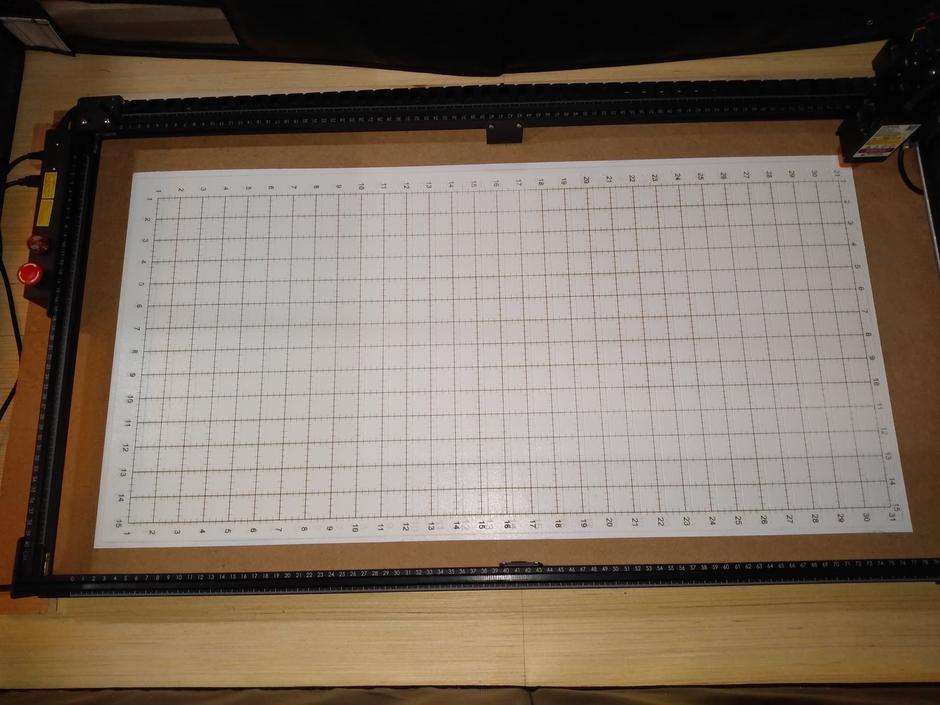
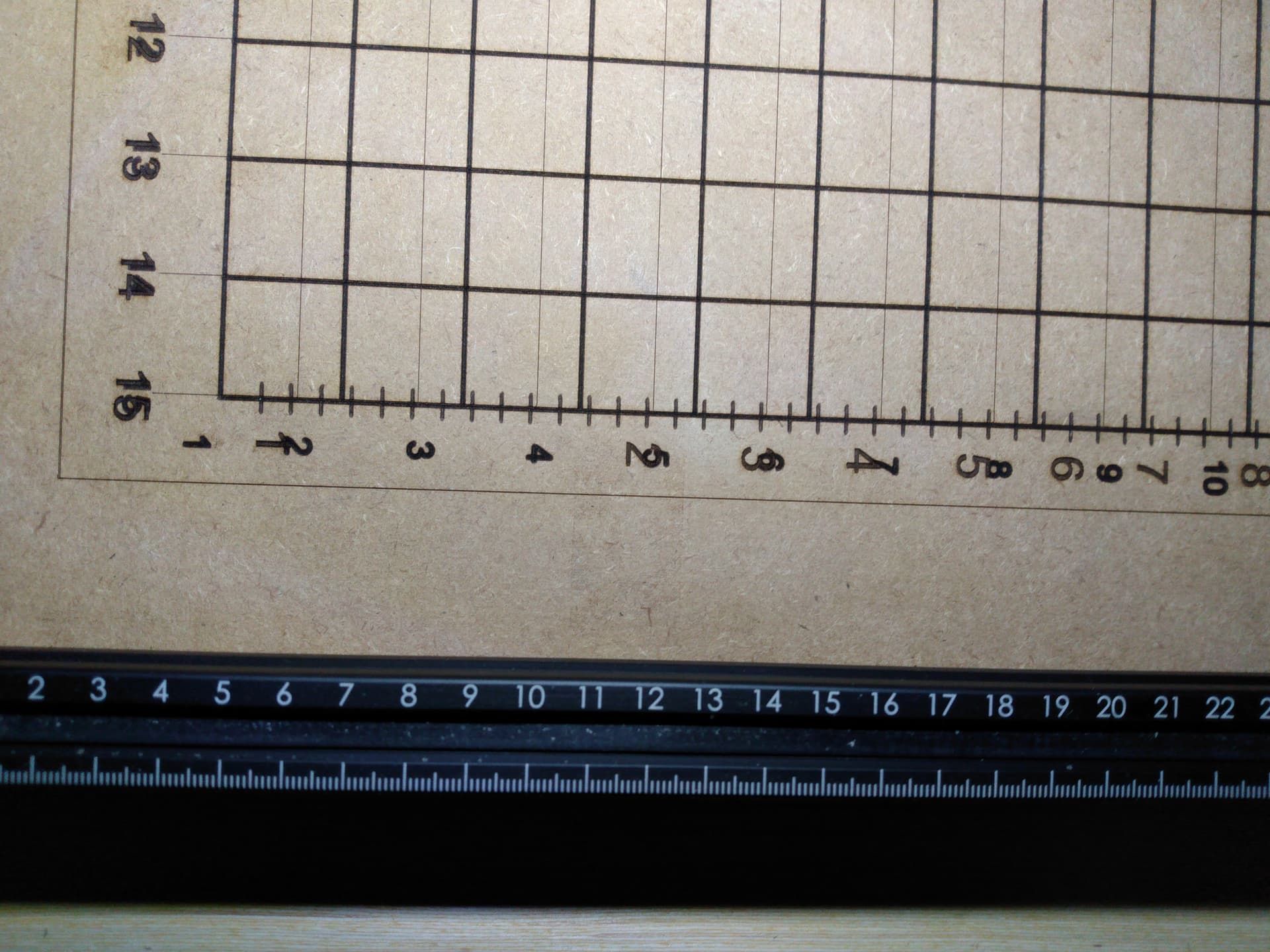
I needed to verify, by measurement, what a complete adjustment of the laser machine did to mitigate my non-linearity when laser burning problem. I painted the waste board, with the old test engravings, with white interior semi-gloss paint so I could see the new test burn after the adjustments, clearly. I noticed the laser head could tilt in the X-axis direction so I squared the laser head to the waste board the best I could without a square and set the optimum height. I checked the power, feed rate, and fill directions for the grid lines and used “Offset Fill” for the number text. I started the program and saw the 1-inch grid lines looked very square. The numbers were lined up to the grid perfectly. I added 10 mil-in thick 1/4 inch spaced “tick” marks that printed flawlessly. The grid lines matched my tape measure perfectly across the full area of the waste board in both the X and Y axis. The results exceeded my expectations.
Thank you for taking the time to show me what it takes to correctly adjust a laser machine. “If you’re not careful you can learn two things in a day”. I have provided a picture of the final results to complete the test data for this post.
Thank you for using your power for good. My problem is solved.
Jim
Lovely example of cooperation and communication in action. Kudos to all involved.
The difference between your first and last pictures shows just how awful the “stock” setup can be.
Your detailed descriptions of the many adjustments along the way should serve as a cautionary tale to anybody expecting to find only one thing wrong.
Thank you for showing your final success!