@ErnieHodge ~ Please do not misunderstand the following, I am trying to help.
We are trying to share that you do not need a printed grid. You can make one, but you do not need one.
If you do choose to make one, keep in mind that it is a more advanced project, ending up with an accurately produced and registered waste board grid. The skills required include a solid understanding of how LightBurn uses its ‘Coordinate and Job Origin’ to define the starting location of any job. This must be understood, then leveraged to produce repeatability of any kind.
Nowhere in the process of understanding do we suggest the use of a printed grid on the laser bed for placement. It is a pain in the backside to set up with no real benefit when using LightBurn.
We offer tools to help you align a job to your workpiece. This is known as “Framing” the job. When you click one of the ‘Frame’ buttons, the laser will start to travel around showing you where it will be working when you send the job. For your system, Oz offered this to help explain: How do I turn on my diode at low power to focus it or frame a job?
I do this all the time, as do a lot of the users here. Many of us will use a jig to do this. Think using a sheet of cardboard where you have cut the same shapes of your workpieces. Pin cardboard to bed, and use the cutout to hold each workpiece in place. Run job, remove finished pieces, replace with fresh stock material and repeat.
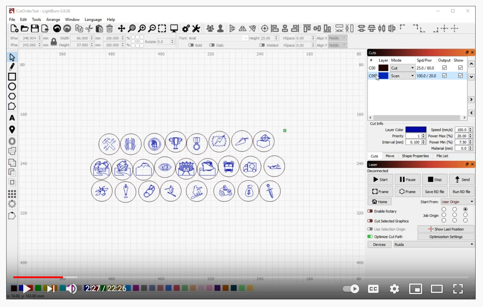
Here I am showing “…multiple designs at the same time”.
With the proper understanding of how LightBurn uses this Coordinate and Job Origin system, along with a good understanding of the hardware in use, accurate and repeatable tasks can and are achieved every day, without a waste board grid.
I’m all good with what you are saying. If I don’t need a printed grid and can make a jig I’m all for that. I actually watched that video when looking on Youtube (I think) and to me I don’t understand how you can do that and not have anything in some kind of order. I don’t understand how you (or anyone) can get the designs on that many products being ‘all over’ the place on the table and have them where you want them on each piece.
I have the Coordinates and Job Origin printed out and have read through it two or three times. One sentence stands out to me at the end of the Current Position section. ‘Using Current Position and Job Origin together lets you line up a cut on a piece of material with ease, once you understand how it works.’ I think that’s my issue, I don’t understand how those work.
If I have multiple pieces do I have to do that every time for each piece? Is there a video on this that I’ve somehow missed?
When I get done with my daily chores I will try the User Origin. I took one of my designs and put it in the upper right area of the LB grid. Do I have to manually frame this with the laser on to get it set to cut or burn? What if I have ten of these to do, how do I do that? I know this is something that either has to be stupid simple that my mechanical brain is not getting or I’m just never going to understand this without a really good video.
Rick, I appreciate you trying and I do understand that I’m not looking at this the way you do but I’m trying.
I think part of the problem might be that you’re trying to land a bunch of designs on existing objects in exactly the right place. You really do need limit switches and repeatable positioning of some kind if you want to do this.
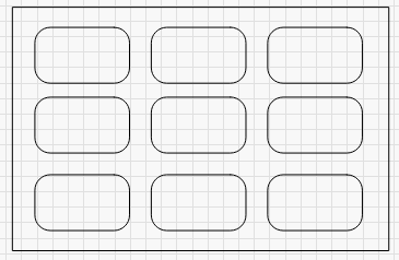
That said, it’s possible to do it a different way. Imagine you have 9 dog tags that you want to run. You make a template shape like this:
Tape a piece of thin cardboard to the wasteboard of the machine, and burn the template into it at low power. Then place the tags in the burned outlines.
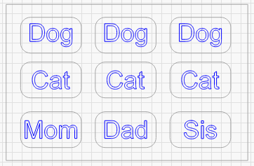
Then, you place the artwork in LightBurn into the template, and turn off the layer you used to burn the template marks into the cardboard, and run the job:
Regardless of the ‘Start From’ mode you use, as long as the machine doesn’t lose steps between running the template and running the actual job, the alignment is simple.
If you’re trying to align on a bunch of different shapes, sizes, etc, then you’re going to have a much harder time, and you might have to line them up one by one. LightBurn has tools for that too, but if your machine can’t run in Absolute Coords you’re going to have a hard time doing ‘production speed’ work.
Oz,
I will only have a couple of different sizes of products so I guess I could do that. So then every time I need to run a particular size I would have to do that all over again (Making a template)?
Should I be using Absolute Coords period? I just came in from trying Job Origin which was a total disaster. I couldn’t get the laser to frame the work. It was at least 60mm off from where it was supposed to frame. I think with all the different things I’ve tried maybe a setting got changed so I’m going to check there.
I’m to the point where I may just need to step away and forget the Christmas sales season. I really don’t want to do that but I also don’t want someone else doing my laser work and send customers inferior work. I’ve had that happen to me from my POD company on something I ordered for my wife. That doesn’t work for me.
At the point of typing this I’ve been sitting here for over half an hour trying to figure out how to ask this question. God how I hate written communications, they never come out as intended.
In your example with the cardboard cutouts, if you want to use that again, how do you line it back up with the laser? That’s kind of why I wanted to burn the work area grid on my base plate. I’ve seen other people who have that (online) and I thought that would be an easy tool to use.
To me that’s the same as mounting an ‘L’ bracket to a base plate, am I wrong? I have a smaller version burned but I decided to try the entire work area grid and it framed it but it just wasn’t framed left to right in the correct place. Front and back was OK.
I had planned to use a ‘L’ bracket on the left side and front because it made sense and would always be a fixed position.
If I can’t have that how do I get this thing set up for Absolute Coords so I can use it? I’m totally lost with what this laser is doing. I’ll pull the settings and add them to this post tonight and maybe that’s got something wrong.
Sorry for the long post and thanks for the help,
Ernie Hodge
PS I don’t consider myself a stupid person and I’ve never had anything kick me down on the floor like this.
Without homing switches, you’d have to line it up manually. I can’t stress enough how much easier your life would be (at least with your laser) if you just install homing switches on the machine and set up the homing cycle. Once you have that, you will have a machine with repeatable positioning, and then you actually could burn a grid into the wasteboard that worked and was usable, you’d be able to burn templates or jigs that always worked, and using Absolute Coords would be trivial.
Without homing switches, you could use an L bracket to butt the template up against so you knew it was properly square, then manually jog the laser to one corner, and use ‘Current Position’ with the ‘Job Origin’ point set to whichever corner of the template you were pointed to.
I don’t know if I can put homing switches on this laser. How would I find out?
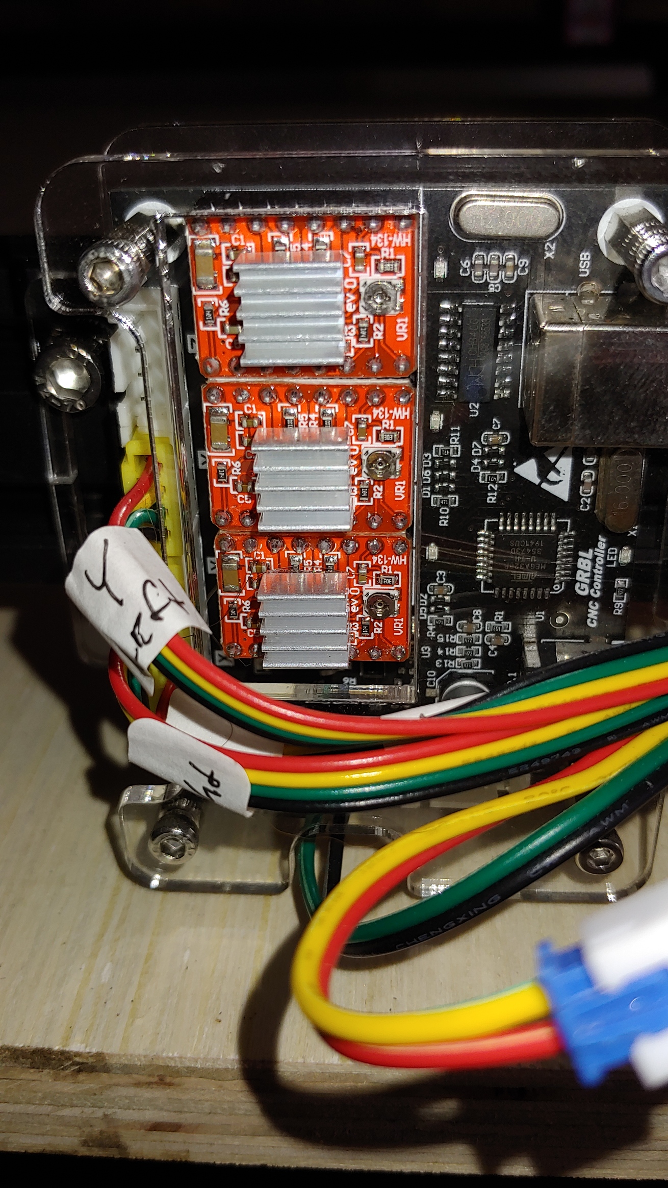
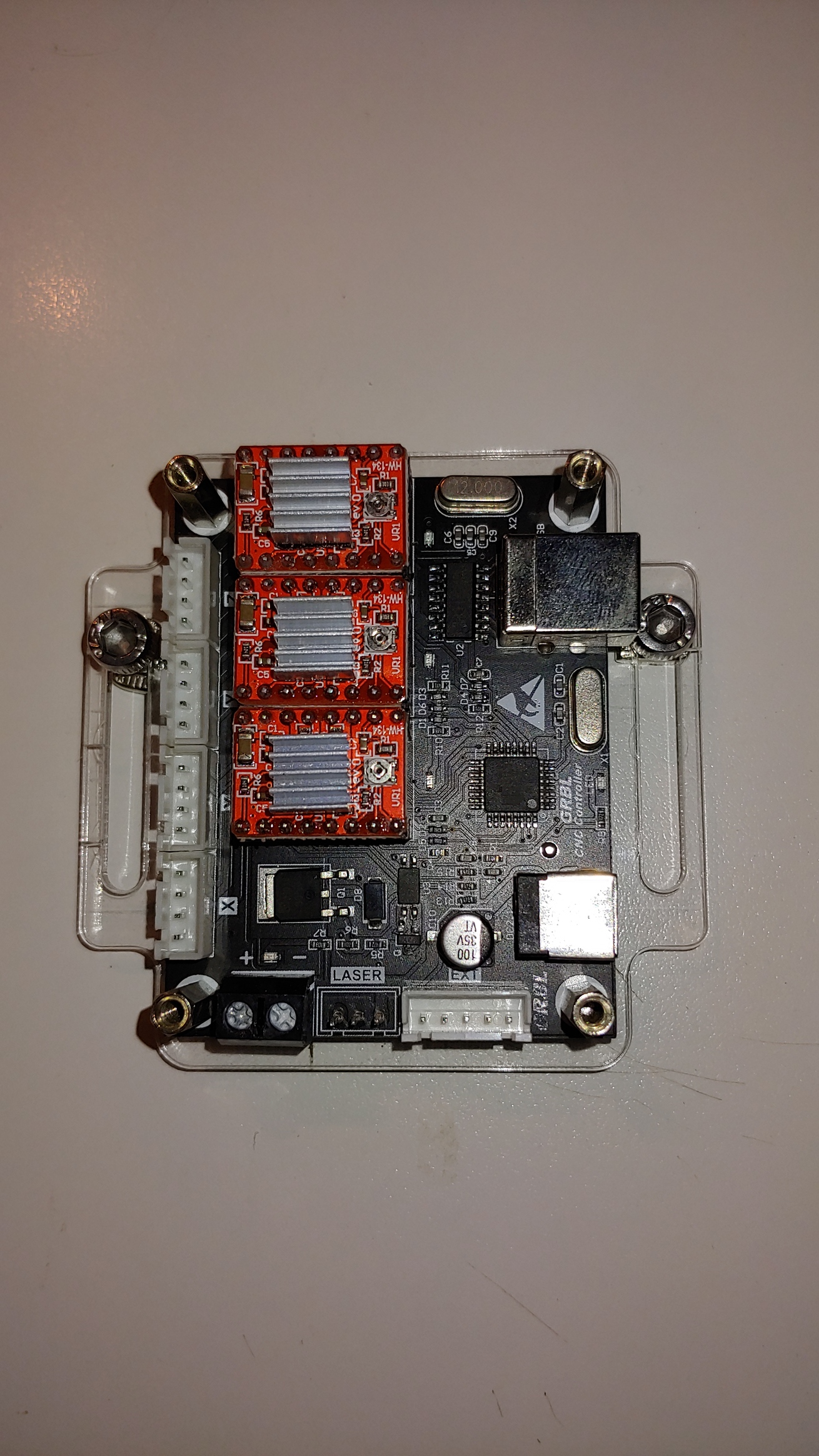
If I get switches which should I get and will I need to update my controller board and the board on the laser itself? I’m going to try attaching a picture of each board in case anyone can answer my question. My board picture for the laser hasn’t come through yet so when it decides to get here I’ll come back and add it.
I want to put homing/limit switches on my laser but I just don’t know which board to order or which switches to order. I watched a video about the Arduino (sp) boards with another add on that goes on that and I’m leaning that way but if anyone has any suggestions that would steer me in the best direction that would be great.
I also wouldn’t have a clue as to where to get mounts and hardware for the switches.
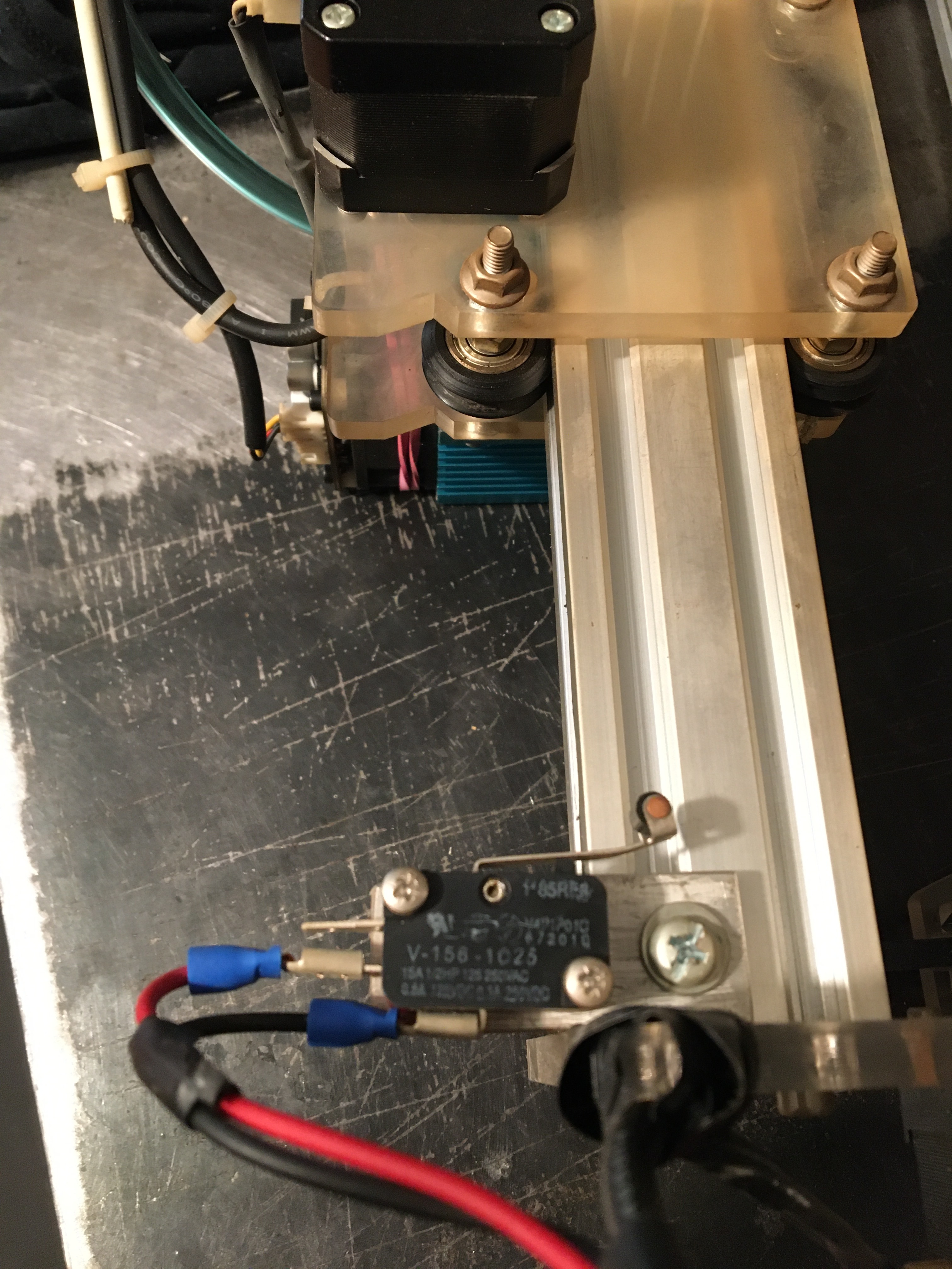
If you can use your controller with LightBurn now, do not buy another controller. You need to find documentation for this particular controller, it will surprise me if there are no sockets for endstops. The pictures show how I made it on my Eleksmaker.
At “https: //awesome.tech/limit-switches-and-homing/” there is a nice description of how it works. However, if you use the search engine with your computer, you will find tons more information on this topic.
I have the website you posted bookmarked. I found it yesterday. I guess I don’t know the proper search terms to use because all I’ve found are Youtube videos with people droning on about how they did it but never ‘show’ how they did it. I’ll keep trying but it looks like I’m not going to get this laser going in time for the Christmas season this year. At this rate maybe not by next year.
I have an email in to where I bought the laser and they are ‘checking’ to see if I can put switches on my laser. I’ll go give my board a good look and see if there is anywhere to hook up switches.
The empty plug socket in the picture is for the Z axis which my laser doesn’t have.
Thank you for your reply and the picture,
Ernie Dodge
EDIT: I’m adding a picture of my board that I just took without any wires in the way. There’s only 3 open connectors on the board when it’s wired. The top left is the Z connector. The bottom left black connector with the plus and minus screws that you can see and the bottom right is a five pin connector. The pins are labeled on the back and are right to left, E0, E1, E2, E3, GRD. I have no idea if that’s for switches or not.
Well after waiting for some other suggestions I just purchased an Arduino UNO board and a CNC shield. Less than $24 for both. I’ll see if I can research limit switches and see which ones work best with the board.
I’ve learned through trial and error that, before doing a production run with the waste board grid, that my first step is to re-calibrate the camera alignment. I put marks within a template space and burn a small filled circle around a mark, adjust X and Y shift until it’s right, and I’m good to go regardless of shapes until I shut it all down. No clue why I must do it this way, but my angst level was markedly reduced once I landed on the process.
Hi. I’m a stubborn American woodworker who is prefers working in inches. Sharing my inch Grid (ungrouped). Inch_grid_with_scale_numbers.lbrn2 (80.9 KB)