I agree with you to some extent - but at this point can it do any harm to try it? I just checked the DC voltage difference between the signal ground at the LPS to the signal ground at CN5 from the Ruida and there is a bit of chatter - up to 5V (at idle) and 1.2V while running but this is a simple multimeter so not sure how high the voltage might spike to.
Surely they must be vectors. You can use the boolean functions on shapes drawn in LB, which aren’t available to images. (and sorry for calling you Shirley). ![]()
I think that board offers level shifting options which you don’t want so just order the 5V to 5V. Not sure about “cable length”. I’ve ordered one too, for testing, might also come in handy for other projects.
you’re measuring a voltage on the ground of the LPS and the ground on the Ruida? There should never be a voltage drop across that… At least not in this low voltage, low current situation since there are only milliamps flowing through that ground.
I hear ya and surely they are not bitmaps. As I was typing that response I was considering how LightBurn would save that as an SVG and it was likely as vectors. I don’t know why they are not a “path” but I’m by no means knowledgeable about this stuff. So they are vectors but not editable via node editor which needs some other type of vector.
The idea was to get lines drawn which could be called vectors and model a file so that it was similar to the pattern which was easiest to show the dots.
They shapes are considered primitives and have properties beyond basic curves with editable nodes. They are still in the umbrella of vector graphics as they are defined mathematically and can scale without information loss. While they are not presented as having editable nodes they do have editable components like width, height, number of sides, etc.
A rectangle primitive with a fill would behave the same as a rectangular shaped path with a fill in terms of laser path… at least theoretically.
1 Like
I’d probably try it, but I wouldn’t be too optimistic.
I agree with @DougL, if you are measuring from a ground to a ground there should be zero voltage. There should be nothing there to measure as they are (should be) at the same potential, ground.
If there is no ‘ground’ or common between them, there is no reference to any signal level.
Your meter is probably fine for this… a scope is nice but is a luxury to most people.
![]()
Should be zero voltage, but if this was always the case ground loops would not exist? I presume a 1.2V difference between optically isolated grounds indicates a (potential) ground loop when connected? I imagine that when they are physically connected the Ruida might “sink down” that difference but it is still good to eliminate this interference with the optocoupler? I’m not an electrical engineer so happy to be corrected.
Can you draw a picture of where the signal ground on the LPS and the ground on the Ruida are connected? Maybe there’s a failure in the wiring.
If there is a voltage change across the ‘grounds’ then the ‘relative’ voltage is increased/decreased by that amount.
An optical isolator is basically an ir diode, so it’s only a load and isn’t ‘floating’. They should be wired together, this would eliminate any voltage difference.
Like measuring the same wire at opposite ends, you don’t expect and there should not be a voltage differential between both ends of the same wire.
Understand about your concern about ‘ground loop’ but doubt that’s an issue unless it’s mains wiring is hosed up… That wouldn’t be surprising.
![]()
Aaaaand its BLEEPing back… Did a quick small engraving in acrylic just to find randoms at the edges of the scan engraved text… GAH… and i couldn’t replicate it in my tests couple of weeks back… what the actual f. Doing my head in.

400mmps, 15% power (remember my laser is 22mA at 42% in LB, yeah yeah, not calibrated LPS). Ambient temp ~20C, water temp ~18C, ran “cold-start” (first powerup of the day).
1 Like
I was just thinking of this dot problem as I have been looking at how the RuiDa uses 2 signals to control the LPS.
Sorry to hear it’s back.
Thinking a bit loud
At this point not too familiar with lightburn or RDWorks; so I’m not sure if it’s possible to disable your laser and have a dry run without using the laser.
That way you are not using the laser but moving like it should (laser still connected of course), if it’s emi of external interference it will likely trigger the tube and you’ll get dots.
Might be wise to check whether it also happen in pause state, or well I mean when the machine is running but you are not doing anything, can be dangerous if it happens even then.
Power supply might also be defective or like above is suggested optocoupler might be a good idea.
The RuiDa controller uses 2 outputs to produce the design and control the Laser Power Supply(LPS). In LightBurn, turning output OFF on the design results in no generation of motion output for that segment. Power would have to be reduced but still set to something for the motion instructions to be generated.
I don’t think the dots are at a different power level as what’s set in the design so if it is glitching on the LPS-L/L-ON1/enable signal you won’t see the glitch with the power set very low.
On my Ruida, I can just turn off the lps independently… Can you do that?
If you can turn off the main power to the lps the rest of the machine should operate the same.
Good luck
![]()
Depends on how yours is wired up.
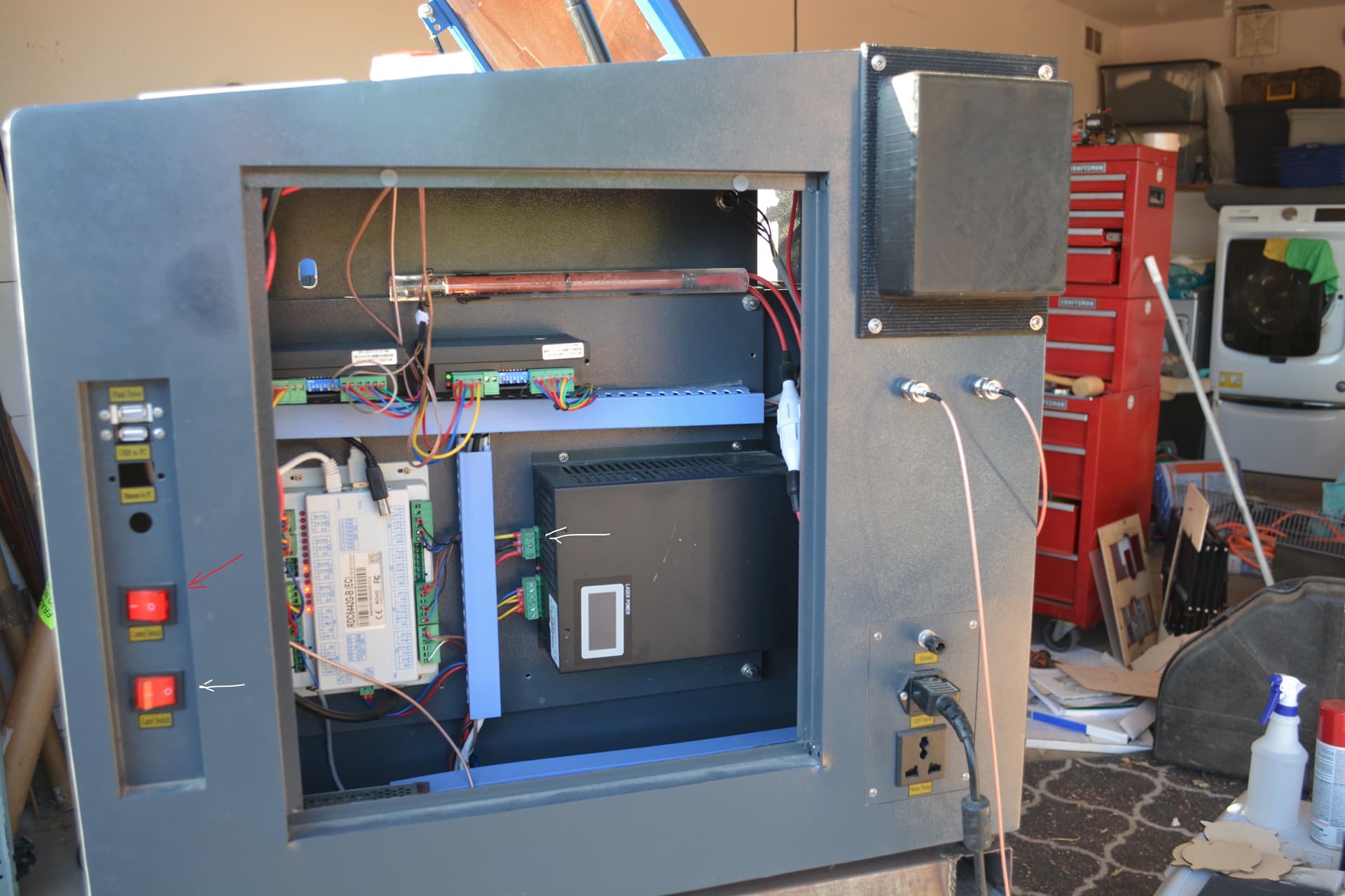
Here’s mine, the red arrow is the main power switch the white arrow is the lps supply.
The main power is on and the lps is off. That’s it normal state if it doesn’t neet the lps, I don’t turn it on… Notice the white arrow on the lps on the right hand side…
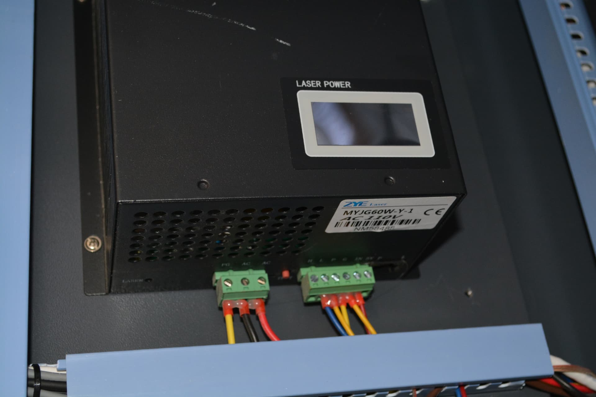
This is a close up of the lps… the connector on the left is power to the lps. You can probably just pull it out if you don’t have switches for main/lps… Maybe more than you wish to deal with… but it’s an option anyway.
Personal experience says the switch option is the most convenient. ![]()
Good luck
![]()
I do not have Ruida laser hardware, but briefly looking though thread I feel that my suggestion may help.
Assuming that problem is not in the controller itself, and not the Laser Power, which as I understand is separate unit, the root cause maybe “ON” and PWM signal integrity issues. Ruida specifies these signals as TTL, that is not very robust signaling for rack or inter-module inside of industrial enclosure with a lot of high power signals. A few things may happened here:
-
ground lift - shifts remote logic ground higher, close to logic threshold, so signal getting smaller, increasing chance of unintended glitching.
-
noise pickup
-
ground loop (kind of the same as above but different route)
Ground lift solution: on diagram from manual posted by Doug there is shared ground path between laser control and chiller. Make sure path is not shared. They may share pin on the terminal but not any length of wire. Use uninterrupted pair, tightly twisted, from the chiller to the controller. Make small signal for laser control a separate bundle (if it is not). Replace ground wire in laser control bundle with wire 2 to 4 gauges larger, then twist all x3 wires tightly together.
Somebody suggested optoisolator. This also can be solution for ground lift and ground loops, but I guess need more knowledge to implement. Looks like Laser Power supply has 5V out for opto’s secondary side.
Noise Pickup: twisting bundles and separating large and small (laser control x3 wire) signals path should reduce noise pickup. Even better would be to use shielded cable. Audio stereo cable would work, I would expect. Do not run/do not share path of laser control bundle in the same chase/conduit/wire organizer as any power circuit wires.
Ground loop: it is not obvious, but there should be only one way ground reaches all corners of setup. Diagram specifically has AC to laser power box with no ground connection, it only gets ground through small signal terminal. I wonder if ground on AC terminal and laser control small signal ground are the same. check continuity - if connected through Laser Power box AC terminals - definitely disconnect AC ground side, keep it only DC power supply side. Last picture appeared to have AC terminal with ground. In such case carefully check to no have ground connection in at DC supply, where it is grounded more often. Only one ground path to every corner of the circuit.
You can try one fix at the time, see which, if any, solves the problem.
Good luck!
Good morning, greetings from Colombia, I also have the same problem q the companions, I really do not know if it is a source problem since my machine has 2 tubes, 2 sources, and in both tubes the same thing happens. I do not think that the 2 sources have broken down at the same time, in addition one of them I do not use almost, so in theory it should last longer like the tube, the tube only has 190 hours of use approximately. Have others been able to solve?