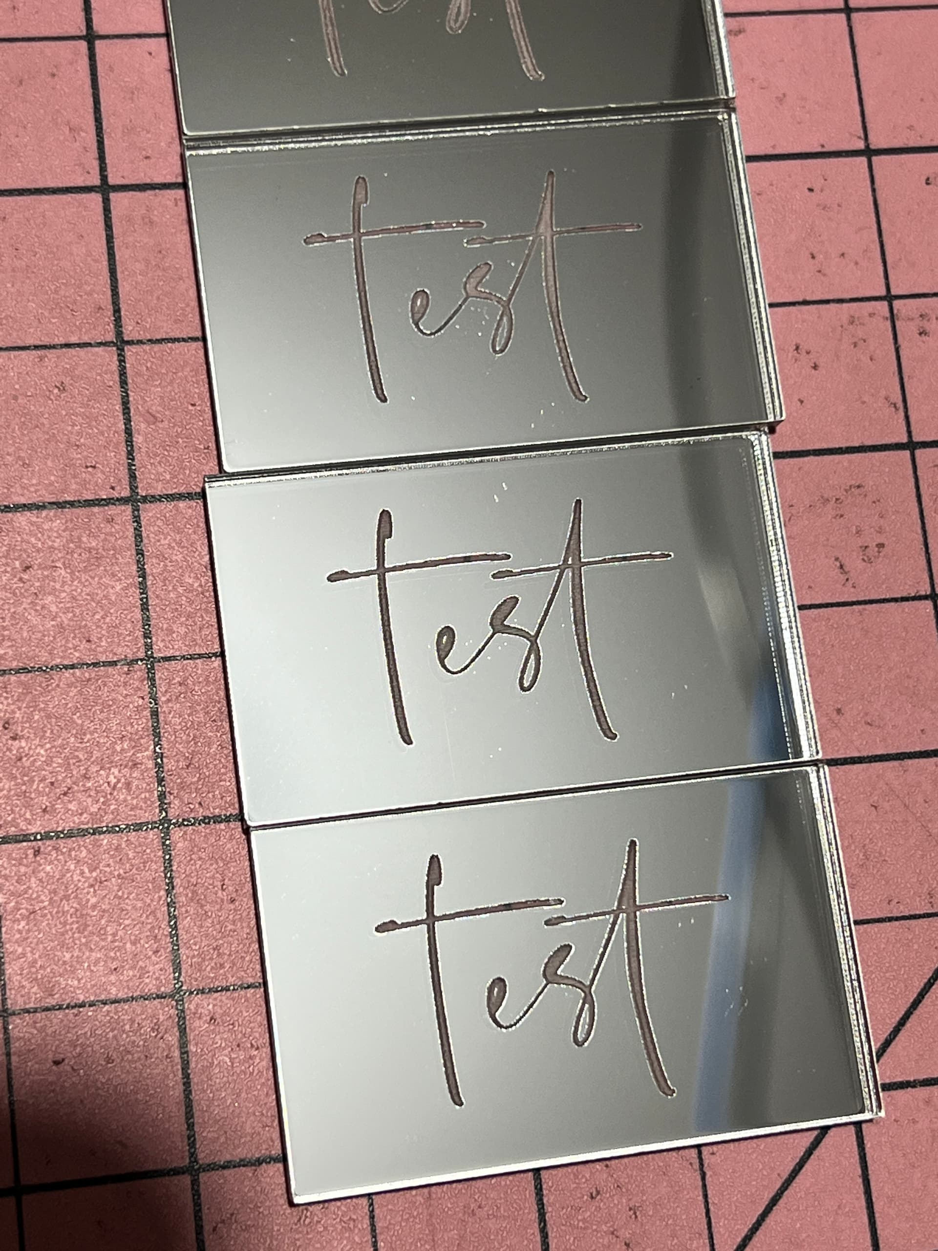
@jkwilborn currently tested right up to 600speed 48 power (40w machine) and dots are virtually non existent at 48 power. However it’s such a deep engrave that it has a bit of a deep halo type look… but no dots! You thinking it’s a LPS thing?
@jkwilborn this machine doesn’t have a mA meter I’m afraid.
I don’t know how to adjust the LPS but would absolutely love some guidance on how to do that… keep in mind I’m no technie please! ![]()
IMO anyone who uses a CO2 laser cutter regularly should have a milliAmp meter on their machine and use the 5V-IN-GND for a POT to set the maximum output of the laser. ie it defines what 100% power is. Then your controller uses a PWM signal into the L input and you define in your controller or software that your using 100% as full power and 5%(or so) as minimum power.
With this setup, as you use the machine you will start noticing it’s not cutting the same as it used to. it takes a bit more power to cut the same. So you can adjust the POT so more milliAmps run through the tube to get you back to your usual 100% power. You might do this adjustment a couple or a few times and each time you should be thinking to yourself, ‘my tube is wearing out, I will eventually need a new tube’… This gives you a means of consistantly using files preset and get consistent results. You can pull out a saved file and same type of wood or acrylic and expect similar results as before. AND you get feedback as your tube wears and needs more current/power to get the same output. I also have a little volt meter on my POT showing me the voltage being fed to the IN signal.
1 Like
@kimmicks07 how is your ambient room temperature? Cold ? The test pictures i posted were done while it was pretty cold in my shop (single digits C above freezing though).
At one point i was suspecting LPS getting too cold. I run chiller 24/7 just to keep water above freezing (i’m in UK, dont really get freezing temps in my shop, but to prevent damage from occasional frost spikes). I dont think its related to tube/coolant temp. My chiller set to 16-18C range no matter the ambient temp (intelligent off, set manually to regulate in that range).
I just re-run same test today at my “bad” range and RANDOMS didn’t show. Nothing’s changed since original test but ambient temp in my shop (summer’ish, yey).
Just some musings. Not sure if any use.
1 Like
@BaronPork interesting!! It’s winter here, around 12-15 degrees celcius but I do run a split system in my garage so it’s quite warm.
It sets the maximum pwm, not the actual maximum current… So it’s actually a poor way to attempt to control the current. The current needs to be limited (set) via the internal lps control.
@DougL described setup is for a K40 type interface and is not the recommended method for connection of a Ruida or other dsp type controller that uses ‘laser on’ and pwm for laser control. So I would not recommend changing any part of that…
Except everyone needs a mA meter… ![]()
@kimmicks07 they are easy to install.
There is a high voltage (hv) line from the lps to the anode of the tube. Steer clear of the anode end and wiring there…
At the other end of the tube (cathode) is the return line to ground or the lps ground. The meter is just spliced into this cathode line, going to ground. The positive site goes to the tube, negative to ground…
That’s it… Hardest part is cutting the cabinet to install it… I’ve mounted mine on the ‘dash’…

If you’re getting 22mA at 42% I’d think your driving your tube at over 40mA, if that’s possible, assuming your numbers are right.
Set your Max power to 50% on the console and see what you get when you pulse it long enough for a stable reading of the analog mA meter… That’s half your driving current…
If you want 22mA maximum current, then at 50% you should read 11mA.
Maybe it won’t be long till you upgrade ![]()
Good luck
![]()
What dpi?
![]()
@kimmicks07 try lowering power instead of increasing. Lower until RANDOMs disappear or you cant get through the mirror/paint. Might work as well…
My range is somewhere in the region of 15-20%. if i go above or below that RANDOMs would disappear.
I’ll do some more testing tomorrow, see if i can replicate and if i do, to determine the actual range (for my machine).
As for proper setting of LPS - mine is all crooked ![]() my 100% power (22mA, keeping safe) is 42% in LB. cant be bothered to stick a screwdriver into LPS.
my 100% power (22mA, keeping safe) is 42% in LB. cant be bothered to stick a screwdriver into LPS. ![]()
I do have plug-in digital power meter, plugs directly into LPS, not an analogue one.
When i kill this 80W noname tube (well, branded CDWG) i’ll install my spare 100W EFR and then fiddle with proper calibration and install analogue ammeter…
1 Like
Whenever i do sustained cuts at 42% (in LB) my meter shows 22mA. Does that count as good ?![]()
Your meter is reading rms current. When a laser lases, it lases at 100% of what the lps is capable of supplying.
I’ll use my tube as an example. My 50 watt is limited to 21mA according to the documentation from the test station.
If I do a continuous pulse, long enough for a stable meter reading at 50% power the meter will read the current over time or an rms value. At 50% and a stable meter reading mine reads 14mA. This indicates the lps is capable of 28mA and that’s what my tube is drawing when it lases.
So I set mine to 10.5mA at 50% pwm, limiting the lps to 21mA maximum and the bonus of % scale in lightburn working properly.
Make sense?
![]()
however you want to call it, setting a DC voltage on LPS-IN does not allow me to use any PWM on LPS-L which can drive the laser over the current setting set by LPS-IN. Even pulling LPS-L low via front panel FIRE button(K40) the laser drive current is limited by that set at LPS-IN.
You can set limits in firmware too but I like controlling the LPS directly an seeing those settings. And like I said, I don’t change them unless the tube starts wearing.
Where is the pwm from your controller wired if not to the L input of the lps?
This is absolutely not true. This is basically the pwm control.
You are still driving your tube at the maximum current your lps will supply… whatever you set the IN voltage to as it’s only controlling the pwm to the lps.
That K40 configuration only limits the pwm range, not the maximum current.
Nothing in the software or controller can limit the lps maximum current.
![]()
the correct statement went like this:
So setting a voltage on LPS-IN, whaterver that does internally in the LPS, it will not allow my to over drive the lase tube, not even when pulling LPS-L low and holding it here(PWM=100%?).
LPS-L is driven with PWM from any controller and I’ve even used LinuxCNC with Remora Firmware on a 32bit board and dynamically varied the PWM frequency and saw expected improvements in cutting and engraving based on the PWM frequency changes.
I’m told that LPS-IN will take PWM or a fixed DC voltage and we know Ruida likes to use PWM into LPS-IN and use a different LPS signal for enabling the laser but then you have to restrict Ruida from over driving the laser when a user says give me 100% power. I have a Ruida controller in a box and have not used one but for a few training classes.
I understand the theory that you are proposing, but when the tube lases it will draw whatever the lps can supply. You cannot lase a tube at less than 100%, the pwm is an illusion that you are controlling the power/current of the laser.
What you seem to be missing is that the Ruida, nor any other software can limit the lps supply current. The only way is via a manual internal adjustment of the lps.
If you look at one ‘cycle’, such as a 50% pwm on an LED laser. When the pwm is high, the device will lase, not at 50% but at 100%. Spread that over the ‘period’ and you have 50% power, which means it’s 100% power for 50% of the time.
All the lasers I’ve dealt with do the same, when they lase, it’s 100%.
The IN controls the internal pwm frequency no matter if you use dc or pwm from a controller but in the end it turns the laser on and off, there is no ‘medium’ during the lase process.
If you don’t lower the current limit within the lps, you will get whatever the lps can supply anytime the machine lases.
The lps is designed for a pwm input for ‘power’ control and L input for ‘laser on’, at least this is the commercial implementation.
With the original K40 sans the ‘laser on’ signal, they use the option of setting the pwm via the pot, and firing the the lps with the pwm to the ‘laser on’ signal from the control board. Effectively the same thing.
If you set your ‘pot’ to 100% power and drive it with a 50% pwm, your analog meter will read half of what the supply can produce.
The simple fact you have to turn it ‘down’ indicates that the lps is probably producing more current than you need, or you wouldn’t have to lower it.
When it comes down to it, there is no real control over a lasers power, only speed…
Does this make sense?
![]()
1 Like
@Jack Good explanation. What sort of frequency is the pulse width modulating at? roughly. Very high I would imagine.
When we reference a pwm signal it is frequency independent. Many call it the pwm ‘base frequency’ but I think the correct terminology is it’s ‘period’.
Mine is set to a period of 50uS (20kHz) normally, but I’ve set it down to 1mS (1kHz) for testing and playtime… The period is simply 1/frequency.
I set my period to 1mS and the power to 50%. At 500mm/s one period equates to 0.5mm in distance covered and gives me a continuous brown line.
Keeping the same settings but increasing speed to 1000mm/s … one period now equates to 1mm in distance covered, so at 50% power I can see, not a continuous line, but a dashed line. This is because the laser is only lasing for half of the period or half the distance covered.
Surprisingly for such a large change in speed, the actual burn mark didn’t show a 50% change in damage as expected. It was very similar to the 500mm/s burn. So similar you had to put them next to each other to see the slight difference.
Besides changing directions quickly, which decreases the overscan and job run time, there isn’t much use for high speeds with a dc excited laser.
I can easily outrun the response time of the lps… ![]() … wish I had an RF excited laser
… wish I had an RF excited laser ![]()
Hope this makes sense to you…
Lasers have been a great leaning experience for me and I try to help other understand the lower levels of how this works. They sometimes surprise me on occasion…
Part of it was that I started in the computer field as a hardware person, so that’s always been there…
![]()
1 Like
Thanks, I see what you are saying now. ie the LPS drives the laser tube with its own PWM at some internally set frequency and we direct/control that duty cycle via PWM and just set upper limits on the internal PWM period with LPS-IN.
It does surprise me though that there is not an accessible adjustment of that tube drive current on the LPS since often people are using 60W LPSs on 40W tubes and given the varying tube lengths it would seem optimal to have access to the setting. Also wondering if what we use for LPS today are anything close to what was originally designed for the K40 LPS. On some forum long ago there was the guy who originally designed the K40 LPS prototype.
So what’s most important to the CO2,He,N2,O2 inside a laser tube? voltage, current or frequency?
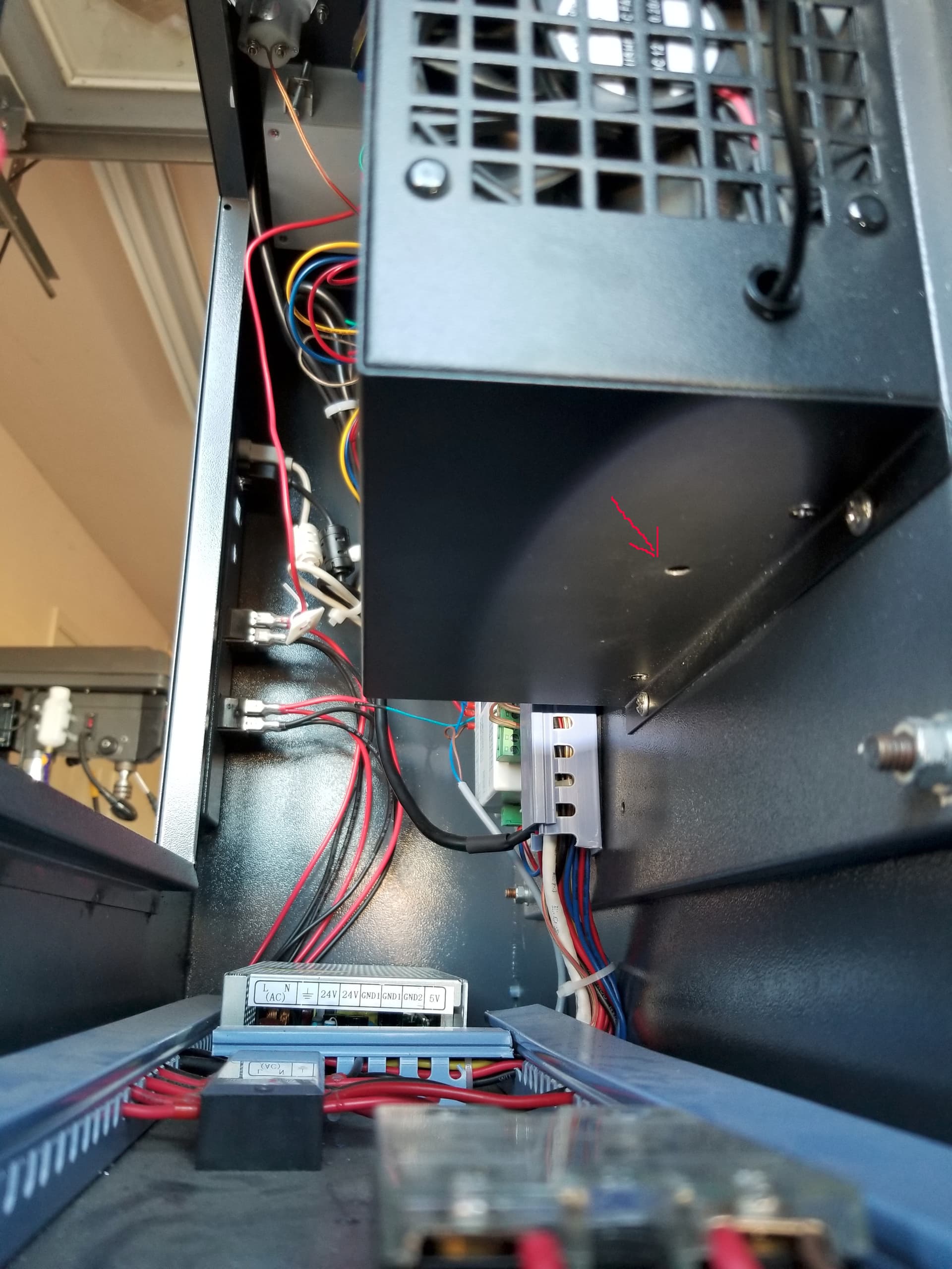
It would be nice if it were marked or obvious. You have to be a contortionist to adjust mine… This is from the back electronics access panel looking up at the lps. It feels like it’s a couple inches up in there…
However the K40 is quite a creation… took me a while to snap on how it was manipulating the lps. Scratched my head a lot…
The control board on it uses an 8051, I believe… I built with and used them back in the late 70’s. We had the programmers and software tools available for it. They must be dirt cheap by now. Considering the cost of a whole K40 is just under twice the cost of a Ruida. I’m sure the found the least costly lps they could dig up. Adds costs to make is adjustable… why would they care…
Also found my steppers getting hotter than I wished, turned down the current to my stepper motors… they seemed to be ‘over driven’ also…
You are right about a larger lps being an issue pro/con. Mine is a good example. My 50 watt (44 measured) has a 60 watt lps. At 50% I got 14mA, indicating 28mA when it fired… Turned it down.
The advantage of a larger supply is a quicker response to the 90% placarded high voltage (hv). The hv has to go higher in the same time frame, so it’s response is quicker… ![]() The quicker the response time the higher the possible dpi.
The quicker the response time the higher the possible dpi.
![]()
1 Like