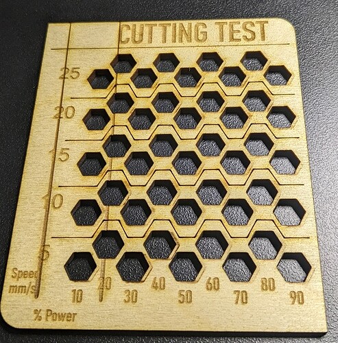
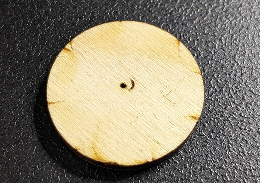
What are these double (phantom) lines during my cuts?

So, I’m up and running with my Monport 60W and I am learning the cut parameters (compared to my K40 experience).

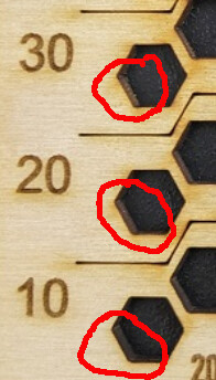
I have noticed a few times, these double lines when cutting:

Tried the search tool but mostly found threads about double passes, not double lines in a single pass. I don’t see it happening everywhere, I’ve never seen it while engraving, but usually cutting and mostly at lower speeds, but it happens too often to not look closer for a problem.

(Please ignore the fact that I was using an already marked piece of material from a previous ramp test.)

Jim

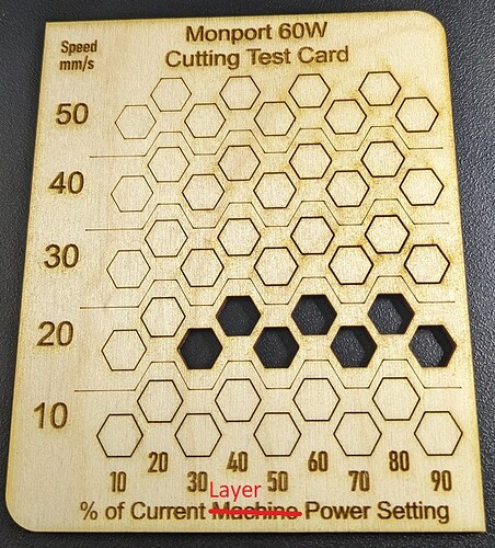
I have to say… this thing can really cut.
Either that or it’s ignoring my Power Scale settings.

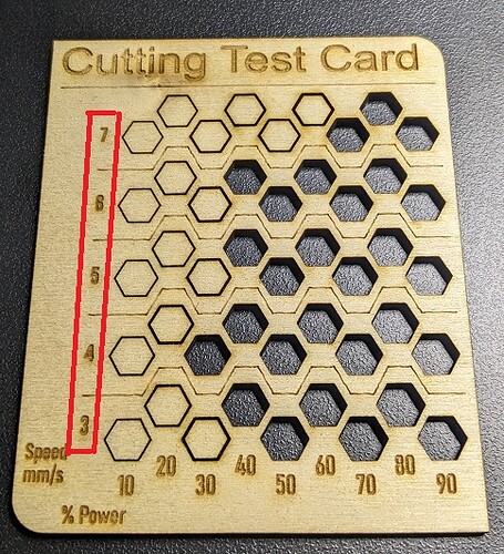
Same card on my K40 (at much slower speeds obviously)

Jim

Lose lens or lens tube…

Your alignment is going astray when this happens, limits what can cause it…

Good luck

:smile_cat:

Checked lens… OK
Checked Tube… A little wobble if I force it in any direction… but shouldn’t be happening at these slow speeds. Dot from pulse at bottom of air nozzle is spot on centered. So it’s not reflecting off the edge or side.
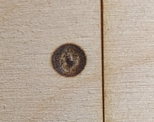
Checked Beam at Mirror 1 (because I knew someone would ask):


(Again, ignore the line to the right… using scrap materials).

Jim

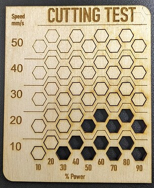
I still think that the Power Scale settings are being ignored on these hexagons…
Why would 10mm, 20mm, and 30mm per second speeds have exactly the same results at 10,20,30, etc… percent of layer settings? It’s almost like they are all getting the same power, just differing speeds (see image below).

The same file (albeit with much slower speeds) on my K40 resulted in more realistic cuts per power.

Since it’s not failing at the time you’re testing it… that is not a viable conclusion. Anything that acts like a pendulum or lever has the potential of moving… You can bend this stuff so it should be firm… don’t muscle it…

I can’t think of anything that can cause what was in your first post except lose hardware… it’s pretty classic that it’s hitting the side of the nozzle… double check the hardware… I’ve seen this a number of times … if it’s something else I’d like to know.

It being intermittent seems a clue to it being lose somewhere.


IMHO, you’re blasting it… you can’t make a good judgement from a burnt hole… Much like your TEM state of the tubes output… a much lighter touch with a wide range of gray shows the power distribution of the tube and hence it’s TEM state.

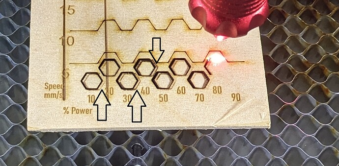
If I look at the posted item, the side of the bottom one is clearly more burnt than the one above it…

Look closely at what I circled … what do you think?

image

You’ve got a machine that’s probably twice the power of the K40 …

Try backing off the power or speed it up, if possible … It’s pretty easy to fry 3mm mdf…

Are you using min/max power settings or are they equal?

This is what they are for, maintain the correct power for a change in speed.

What do you think?

:smile_cat:

Those double lines , or Ghosts, could be the laser bouncing off the focus tube. If after a run the tube feels warmish - hot, that’s what is happening. The beam will still look good, but you do get a bit of bouncing of the sides, causing a double line. If you use the double side tape test, make sure that the beam comes out CENTERED from the bottom of the focus tube. BTW: I am also seeing a problem with your Y axis in the test card you showed. Compared to the K40, the Y axis on the horizontal lines seems to be moving around a bit.

Well, I’m at work today, and not in front of my laser… however last night I modified some parameters of the Min/Max settings and learned a bit more about the Lightburn Power Scale feature. In specific, that the Power Scale is “a slider between the Min and Max settings.”

Previously, my Max was 100% and my Min was around 65% which explains why all of the hex’s were cut out regardless of speed. Since then, I have dropped my Min to about 11% (the lowest point at which the laser will fire) and now I see some gradient in the Power Scale settings.

Oddly… the lower group (10 mm/s) will not cut at those settings. The next two groups, at 20 and 30 mm/s cut fine. I could not figure this out and assumed that something in the file was corrupted (my go-to excuse for not being able to solve a problem logically). So I opened a blank workspace and created my own cut card from scratch… using the previously “purchased” file as an example. I set each speed to a different layer, and then each hex to a different Power Scale. I got the exact same result. The laser refused to cut the first group of 10 mm/s hex’s. The setting for that layer is Max 100% and Min 11% (the same as all the other layers). I have got to be missing something here.

Why would it cut the same information at 20 mm/s but not at 10 mm/s?

Jim

[Edit: One more note… best I can tell, the milliamp meter on the side of my laser power supply never changes during that lower 10 mm/s set… it remains around 3-4 milliamps. But it does seem to scale up on the other sets.]

Check the start speed in the controller and see if that’s an issue… I wouldn’t expect it, but since your going down this road you should be aware of it.

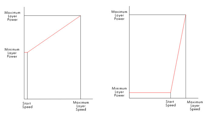
Min power is maintained until the machine reaches it’s start speed, then the power increases… Here is some rough graphics to help you visualize it.

Doesn’t seem to explain your issue, but though I’d give you a heads up about…

:smile_cat:

1 Like

So that was something I wondered about. Correct me if I’m wrong here, but Lightburn can only use the power range between Min and Max that is set on my Ruida Controller… whether that comes from a layer setting or a Power Scale setting on a layer… yes?

For example, my K40 had the digital meter on it (which I later upgraded to add an Analog Milliamp Meter). I had it set to 40 (percent of laser power supply - not laser tube as I understand), because that created about 15 Milliamps at the laser tube and would not over drive it. Then anything Lightburn wanted to do would never stress the tube beyond that limit.

Tell me that DSP on the Ruida works the same way… I can set my Min on the controller to the lowest the tube will still “spark” at (the feature you are calling the “start” speed), and the Max to the amount I never want to stress my tube beyond… and Lightburn will always work within those parameters from its 0% to 100% range. Correct?

Jim

[Looks like I might be drilling that 2" hole in my brand new laser this weekend]

Oh, and for whatever reason… the double lines are gone.
Never found any hardware problem. And my beam from mirror three shoots right down the middle of the tube.

Jim

1 Like

Actually there is a place specifically for setting the acceptable pwm range. This is the last group (I think it’s labeled laser) in the Machine settings.

This should be set to be within the limits of a proper lase. It’s the same on many machines, these speed limits are there to protect the machine and will not allow the pwm to go above or below these limits. There are also speed and acceleration to name a couple of them.

If I gave you one of my engraving files that I run at 1250mm/s, it would probably not run well on your machine. These internal settings would prevent it from attempting the operation.


Don’t know your electronics expertise level, when you read a value on a voltmeter, that value is usually for DC, such as our mA meters. Put a DC power supply on the a meter with 10mA current and the meter will display 10mA, as expected.

If you change from DC to some type of alternating input, like the current flow out of the cathode of your tube, the meter will display an rms value (average), not the actual peak values.

We do this all the time when we measure the pwm output at 50% and read 2.5V, we know there it’s a 0 - 5V signal, but it’s only on half the time … I.E. we don’t read 5V for any pwm setting, except 100%, although we know it is a 5V signal.

Easy to work out mathematically with a digital signals, a sine wave or other analog waveform will have a different rms value.

The rms value of a pure sine wave, if I recall, is the square root of 2, so it’s about 1.41. Your mA meter does the same thing …

In real life, you read 10mA, it’s probably more like 14.1mA of current at it’s peak, but averages out at 10mA…


As a green user of a just purchased co2 laser, I had emailed Russ Sadler about how to set this up for the proper current.

He advised me to use 50% pwm and set the lps internal pot to half of what your maximum current flow that you wish to use.

When this is done, you select 50% power in Lightburn, you will get 50% power out of the tube… it will sync up correctly.

My tube had a 21mA max, so I set it internally for 10.5mA at 50% pwm.


With a dsp, there are two control lines, the pwm (-> IN of the lps) runs constantly, running a layer, no matter if it’s lasing or not. The other is the L-On1 (-> L of the lps) which is laser enable. This actually tells the laser to lase.

The normal lps has an IN input, that determines or sets the current flow, and an L input that causes the laser to lase when it becomes active. Meaning that it takes two signals to control the lps.

The IN input, from history, is an analog input, but all of today lps will take both analog and digital inputs for the IN terminal of the lps.

On a K40, this is the pot you twist with it’s wiper connect to IN of the lps. Supplies a 0 - 5V analog signal to the lps IN terminal.

The nano can only produce a single pwm signal that turns the laser on and off… so instead of it controlling the power to the lps, it’s controlling when the laser lases. It’s usually wired to the L (or H, inverted L) terminal…

The problem is, that if you twist it to 15mA, then use the pwm, you will have to do power conversions such as I want 80% power, but I have to say 80% power of the 90% setting and do the math… so it doesn’t line up with percentage of power.

I hope this makes sense, did realize it was so wordy…

This would have to be a mechanical issue… likely you unknowingly fixed it when you were checking things…

:smile_cat:

1 Like

I’ll take a look for those when I’m back home.
(After saving my current settings to a file, of course).

Nor do I… but I’m always on a quest to learn more.

Your words are quite effective… but your diagrams are even better.
Thanx.

I’m not yet convinced of this (stubborn is the word my Dad would have used)… I can almost bet you if I reset my Min and Max to 65% and 100% I can cause this again. I’ll have to see later.

Might take you up on that… :wink:

:smile_cat:

1 Like

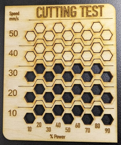
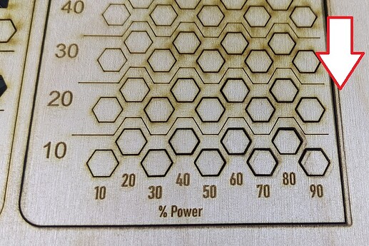
Finally… a cut card with expected results…
I found that speed setting in the Machine Settings… it was set to 15, which is why my 10 mm/s hex’s were all wrong. Just for kicks I set it to 10 and got the same result… so I set it to 9 and my 10’s started working.

I took this shot before removing the material from the bed. Most of the 10’s fell out… some of the 20’s fell out… none of the others cut through.

Notice the double line has returned…
So okay… I owe you a drink (or whatever we would have bet), it would appear that my #3 mirror was ever-so-slightly OUT OF WHACK. I did a simple focused pulse and got this:

And with the slightest little nudge to the right with the mirror adjuster… I now get perfect pinholes… without the smiley face. Thank you for being insistent with your response. I stand corrected.

My last cutting test is below (and was done after the focus tube mirror #3 adjustment).


(The shadows at the top were from another test run on the backside of this 3mm Birch Ply.)

Jim

1 Like

Interesting that you effectively get no improvement in cutting performance after 50%. Do you see an increase in current above 50%?

Are you referring to the fact that there are no hex’s cut out of the 30 mm/s set, even above 50%? Because there were removable pieces at 30/80 and 30/90, but I had to push them out with a tool… and I don’t consider those “successful.”

Jim

Yeah, precisely. Your progression seemed fairly linear up until that point. There’s likely something going on there but no good hypotheses at the moment.

1 Like

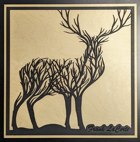
Well, it’s pretty clear that my 60W Monport is not going to be cutting 3mm Birch Plywood at 30 mm/s any time soon… so tomorrow I’ll split this test up at 10-15-20-25-30 and see what the curve looks like. 30 mm at 80% and 30 mm at 90% do in fact cut through… but if I tried to use that setting on something as delicate as the Deer below… I would be struggling to separate the wheat from the chaff, so to speak.

A few things are becoming obvious to me tonight:

  1. I’m going to need to install this 30 Milliamp Meter I’ve already purchased.
  2. I need to buy some more 3 mm Plywood.
  3. Time to try some MDF.

:smiley:
Jim

1 Like