What causes this?

Does anyone know why the lines when the laser head engraves from right to the left side are wobbly? I really tried alot, for example checking all screws, greased the gantry, checked if the lens is fix, checked the belts and so on.

If I change the fill settings so that the laser only engraves from left to right I don’t have that problem and only get straight lines. I just can’t figure it out and that is annoying. I posted it in the omtech laser groups an in 3 other laser groups and so far no one had a clue.

I set the line interval that big because I wanted to set the scan offset, that worked fine.

(another thing is I did a test where I changed the engraving 90degree and rotated the text and when the Y axis is moving the scan offset is not good again, any idea why or where you can change the settings so that it aligns in the Y axis too? .)

2 thoughts: 1. The grain in the wood makes the burn appear wobbly. 2. Is your lens tight on the lens tube?

I’ve just popped this post into the Community Laser Talk category, as the Hardware Compatibility category is more for connecting hardware to LightBurn, and it seems like you’re sorted there given able to run jobs.

To me, this looks like it is what’s called “ghosting” in the 3D printing world. I say this because the wobbles seem to be happening after a direction change (a jump to a new line), but not elsewhere (a break in a line).

Basically, it looks like the inertia of the machine’s previous movement is fighting the ‘new’ movement the machine should be performing. e.g the machine ‘wants’ to keep moving down, even though it’s being driven to move left, resulting in wobbles.

This can be a symptom of many mechanical issues, many of which you seem to have already explored; loose belts are usually the culprit (but you don’t want to over-tighten them either, they should be able to be plucked like a guitar string), upgrades to tool-heads that increase weight are another common culprit, more weight=more inertia= more force for a machine to fight.

However, ruling out hardware, it could also be your settings; the most common culprits are the speed or acceleration set too high for the hardware to handle. I’d probably try lowering the speed (and power, if you want to keep a similar burn effect) just in the layer edits for now, and seeing how you go.

If that turns out to be the issue, you may wish to make the change to the machine settings so they’re permanent moving forward: Configuring A Ruida - LightBurn Software Documentation

If you notice a change it would also be worth checking if this is happening when a burned line changes sharp direction, or if it’s only after travel moves (if only after travel, you might only need to change travel speed, if your machine supports editing these separately).

If there is any suspicion of it being the grain, turn the material 90 deg…


I think @BillieRuben is correct about the mechanical being the most likely issue. Not because of directional changes or acceleration as there isn’t any being applied where the error is occurring.

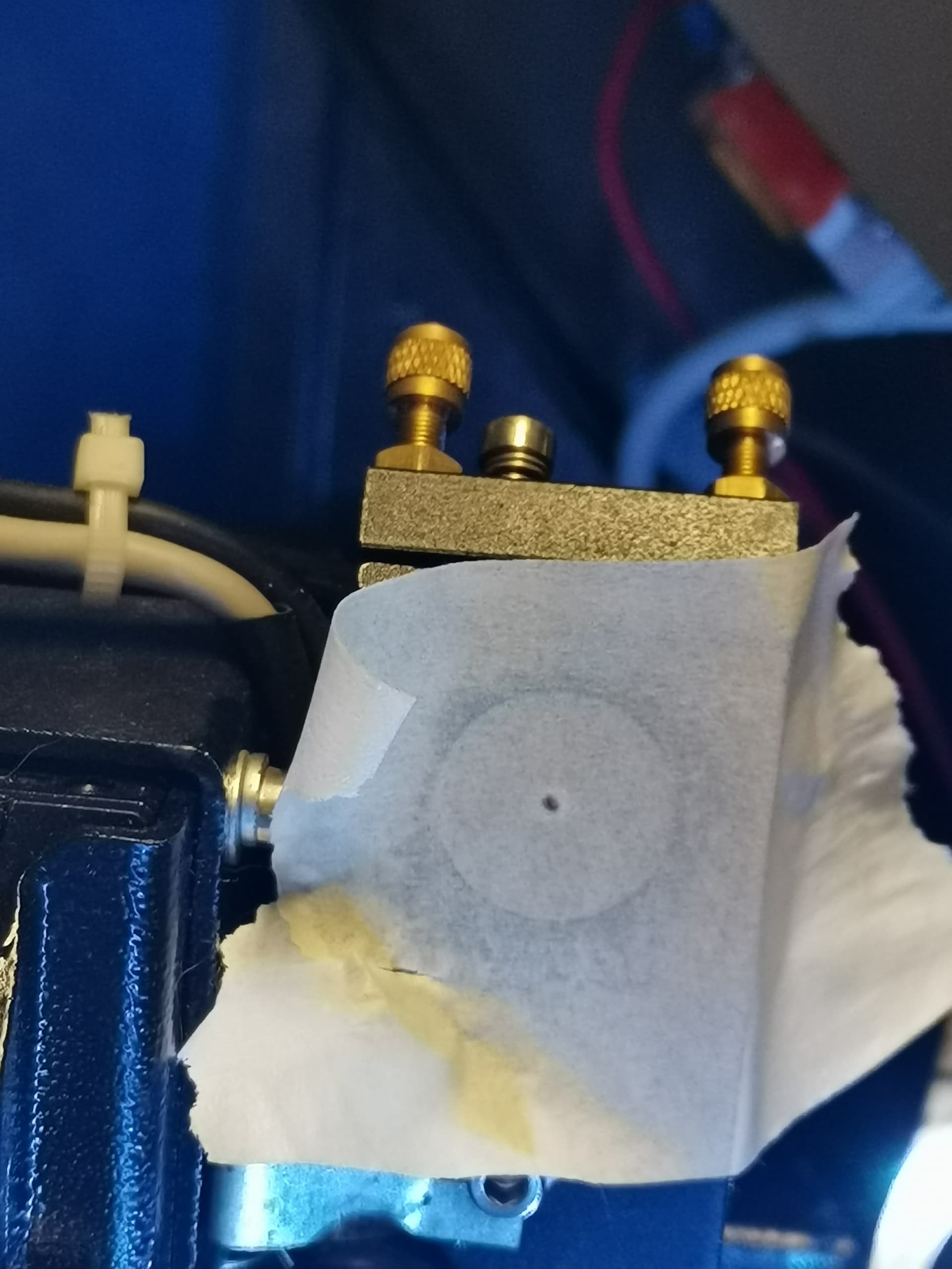
The only thing that could apply here is if it’s at speed and it’s still wobbling. The right side of the image isn’t visible to see if it’s occurring there…


I do think the the way the Ruida operates should be considered…

In scan mode, the head is at speed the entire time it’s lasing, or there wouldn’t be much point in setting a scan speed… in simple terms the Ruida is not ‘slowing down’, ‘speeding up’ or ‘changing direction’. There is no point of a minimum power setting when engraving… with the exception of grayscale …

This is not true with vector cuts…


Watch the head, in bi-directional operation, to determine which line is wobbling … going right to left or left to right? This will help to locate whatever is lose on the machine… hopefully…

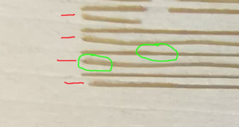
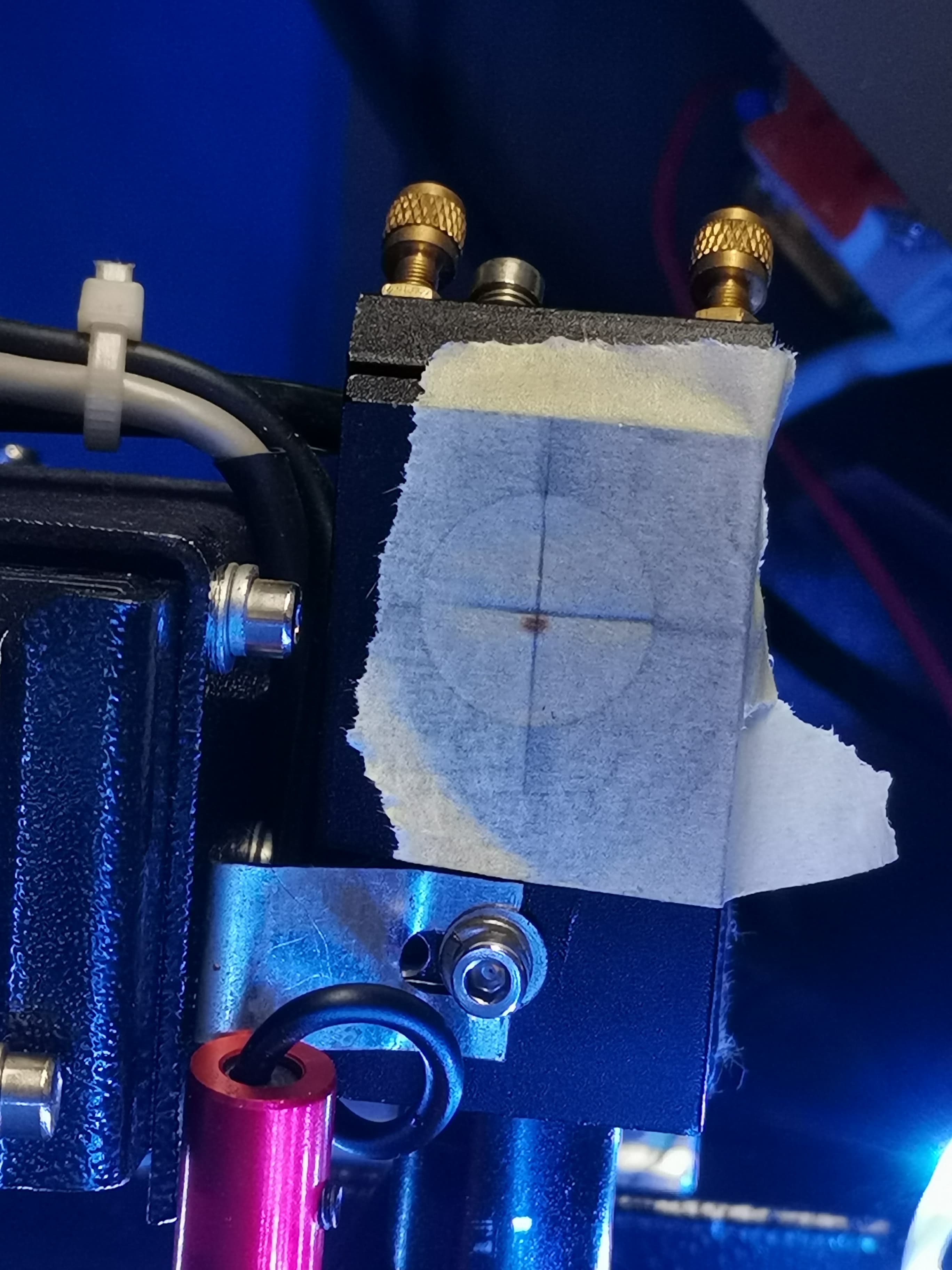
The red lines are ‘wobble’ lines, so it’s only occurring in one direction, which is probably why it ‘goes away’ when you do it in single direction mode.

I notice which direction the head makes it’s first ‘burn’ line and count up till you get to an anomaly.


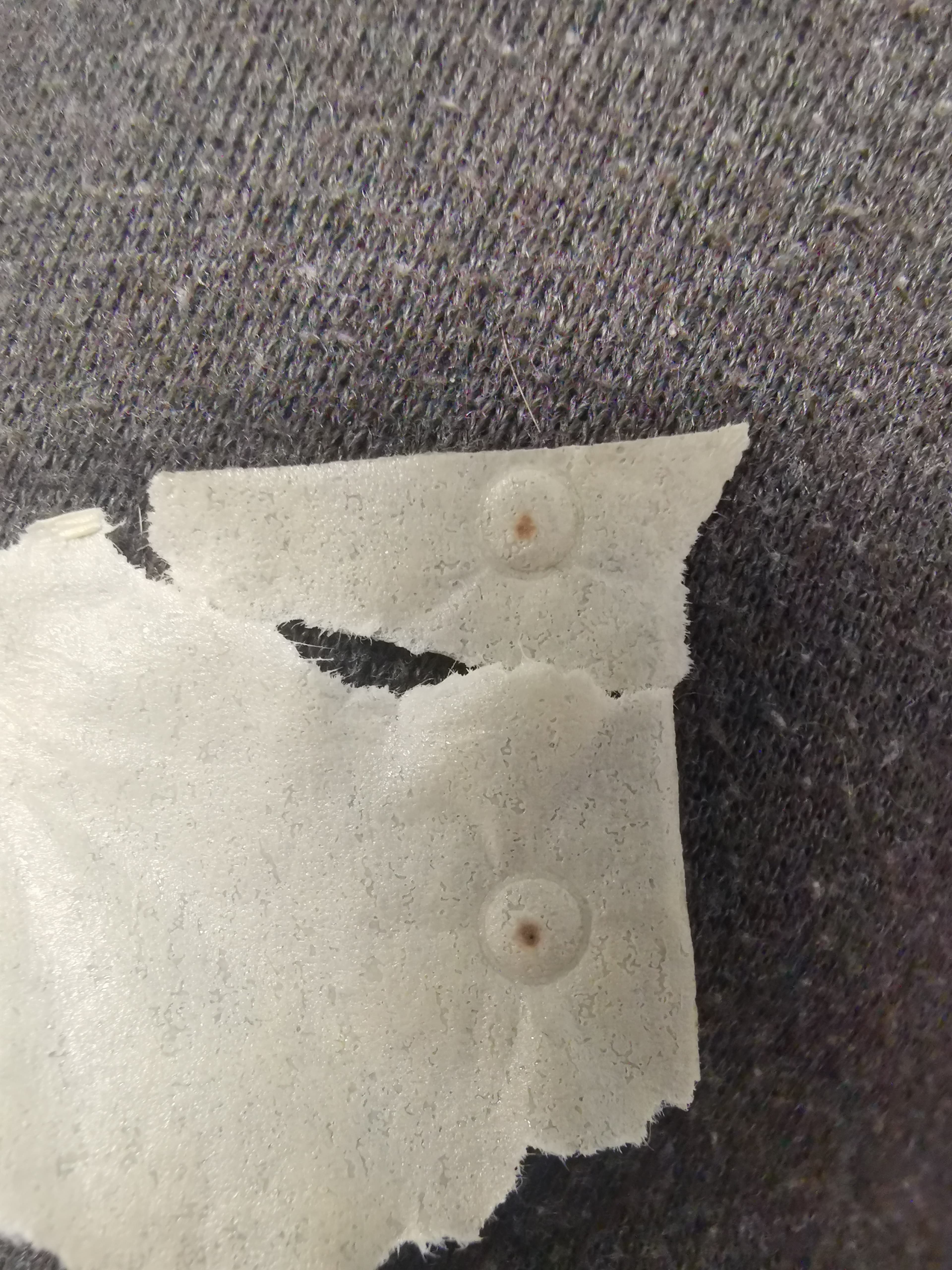
The green points to focus issues, one of which is not on an offending line. Some of this may be a variation of the material, like the one on the right, but the left one is definitely not from material.

I don’t think either is actually material related, but we can debate that…

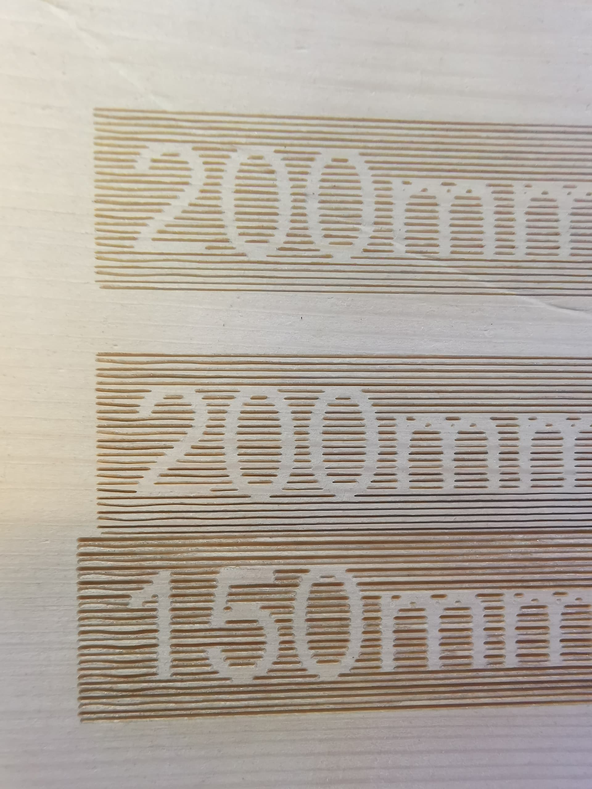
None of these ‘lines’ really look ‘right’ to me.

Why such a variance in line focus in such a short distance…? And why is a ‘good’ line out of focus…?


All of this looks mechanical as I don’t know how you could make these happen in the software… and it’s not related to acceleration or other changes the machines applying to the head.

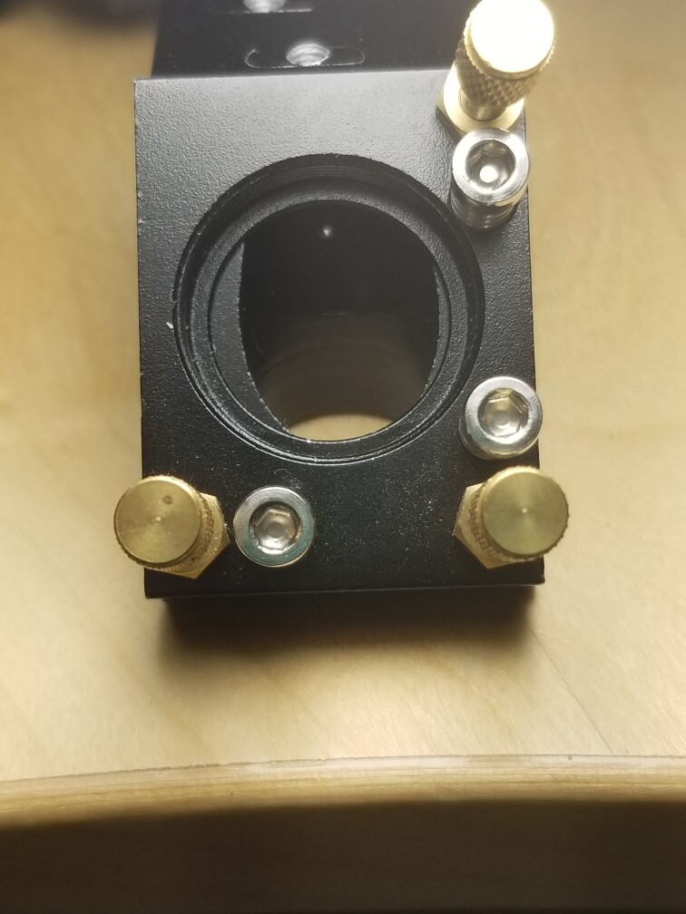
IMHO, you have a belt/pulley/head mechanical issue of some kind.

I’d determine which direction the issue is occurring. That might help you figure a likely cause… where are you physically engraving this on the bed? Does it change at different locations?

From the picture, I’d say it’s ‘not right’ on the first line, assuming it’s staring at the bottom… so I’d look at that direction first.

Good luck…

:smile_cat:

I just tightened all the screws I could find and some were not that tight but after that I did a test and saw that I get different dot sizes in each corner of the bed.

I spend the whole day today to realign the mirrors and I would say they are really good now.
They hit on top of each other in every corner and also get out of the nozzle quite in the center.

The only thing is that they all hit mirror 3 a little bit too low, but I don’t understand why the front right side has such a good engraving and cut and the back left side of the bed is terrible.

I have to raise the tube a little bit more tomorrow and test if that is the problem because I hit mirror 3 a bit too low but it’s strange that one corner of the bed is looking so good and the rest not.

Here some pictures


M3 is a little different as the beam has to down the center of the tube.

‘too low’ doesn’t have meaning when referring to m3, at least to me… I will assume you mean ‘low’ as in the head photograph…

You will have to move the beam ‘up and down’ (z axes) for it to center in the tube ‘right to left’. You have to move m2 (y axes) for front to back tube adjustments.

M3 might not be like the others for various reasons… including

You’ll notice the center of the hole is not the center of the mirror… at least on my machine and this head…

How do you determine how it’s going down the tube properly?

If you do this, it will have to be re-aligned through all three …

I’d advise to leave the tube alone,t unless you can’t make the required adjustment… if you raise it, then you will have raise the other two to keep them centered…

:smile_cat:

What do mean with move the other 2?
From my understanding it’s just important to hit mirror 2 in front and back position at the same spot so that the laser beam moves exactly parallel to the Y axis.

What I know it is only important that on mirror 3 you hit the center in all 4 corners of the table so that the laser beam can move down from mirror 3 to the lens.

Am I wrong?

Those photos show where I hit mirror 3 at best and at the worst corner. Looks quite center to me


Assuming you raise the tube squarely, the beam will raise and the spot on m1 and m2 will also raise… to compensate you have to move both mirrors.

Actually this isn’t true… you want the beam to go down the center of the tube and squarely hit the center of the lens. It might not be what you expect on m3, like not centered. There is no movement between m3 and the lens so it could be off from what you might expect to see …


As I pointed out before, the center of the hole isn’t necessarily the center of the mirror.

In the photo I posted you can see the ‘hole’ behind the mirror holder and it is not centered with the mirror mount.


Ensure if you can it’s going down the center of the tube and hitting the center of the lens…

Tape on the end of the tube also works.


It looks close enough that I think it should work…

:smile_cat:

I understand, it’s just strange to me that I hit mirror 3 at both corners at the same spot, and get different dot sizes.

So I would assume to get the same result, but no.

I have to check the head and mirror 3 where the center is, maybe I’m off a little bit. The last thing I try tomorrow, when I can’t get it running after that I will look for a laser service technician.

It seems pretty clear that the motion related line-end symptoms would be greatly reduced by tightening the chassis hardware - so that’s a win and a step toward the goal of consistency.

Have you considered the possibility that a twist may have been introduced into the shape of the gantry by tightening the screws?

Checking the chassis (and then the gantry) for square and level, with a small torpedo level or a ‘combination square’ may show you something hindering mirror alignment.

Yes everything is level, also checked the gantry, looks also good.

I swear everything is aligned to perfection, it cant get any better. I hit every mirror at exactly the same spot everywhere on the bed. Also checked today that the beam is going down at mirror 3 exactly in the middle of the tube so it is hitting the lens also dead center.

At this point I’m done with it, over 5 days now and it doesn’t get better. I have a little bit of play in the tube where the lens sits but Its only when I push with some force against it. Maybe that the problem I dont know.

I will contact a service technician and maybe he can solve it. I guess over 50 different people tried to help me online but everything they mention I have already checked 5 times and realigned it to perfection.

If it’s not happening at the other end of the lines then I’d suspect some wobble in the linear rail sled. I can imagine this happening if the balls aren’t circulating on one side. Alternatively, it might be wear on one side of the rail itself at that point.

But when I only make a pulse on the material in each corner with the same focus distance I get a way bigger dot in the back left corner.

Try making a pulse without a nozzle/lens in the four corners and compare the result.

With regards to the wobble, try going to Edit>Machine Settings, and decrease “Engraving Y start speed” from whatever it currently is (15?) down to 1. “Write” the change, and then for good measure go and push the “Reset” button at the control panel on the laser.

This will slow the transition of Y which provides a brief interruption & absorption of the vibrations @BillieRuben was talking about (which might normally be minimised by a jerk reduction, and in my experience are more likely to occur on larger sized machines e.g. 1300mm gantry which seem to amplify inertia/vibration/resonance issues).

See what sort of difference that setting makes to the output, and perhaps gradually increase it until you find an acceptable compromise between quality and loss of time.

2 Likes

I would have thought it to be the axes ‘jump off’ speed… The start speed has to do with where minimum power will start to increase. At least this was my understanding.

The jump off is what speed that axes will begin to move…

That’s what I’ve been using … :thinking:

This is a band aid, not a fix… Something else is not right…

@Luckypirat – Have you done a resonance test on your tube?

You tube should resonate in a TEM0 state. If you’re sure everything is OK this should be quick and easy confirmation it’s not a tube issue.

:smile_cat:

It’s less a band-aid and more a way to narrow down the cause of issue. I think it’s really worthwhile trying what @NicholasL suggested!

I wasn’t po-poing the tact, just pointing out a fact.

Anything to help diagnose it would be great…

It’s still clearly mechanical.

:smile_cat:

Focused on 3 corners and not one got my attention. That tells me there is a Z difference on one corner. Maybe stretch the cabling at that corner? Maybe table not flat on all directions? Maybe slightly twisted frame? Shim bad corner with a piece of paper and see what happens. I am not a Laser Guru, so ignore what does not apply. I am just throwing out ideas based on my 3D printer (I hate) experience.