Hey guys, i have a problem since over 5 Months with my 100W Co2 Omtech Laser 50x70cm.
I get a very bad engraving result in one corner and bad engraving results in 2 corners and only in 1 corner where the laserbeam travels the most distance i get a good result.
I have reall done everything multiple times, aligned everything to absolute perfection over and over and over again and asked in literaly every laser group on Facebook for help but still no one could provide me a solution.
Thats why i ask here, maybe we have some experts here that now what the cause of my problem is.
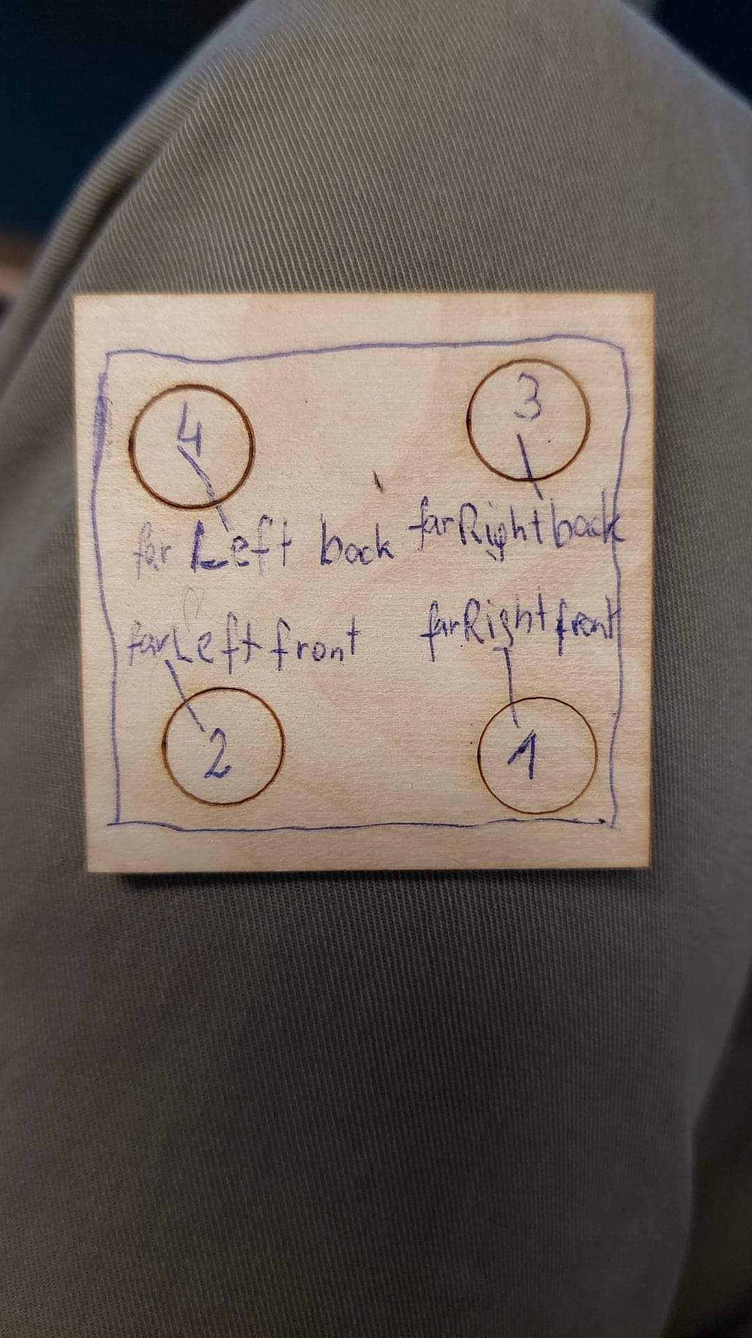
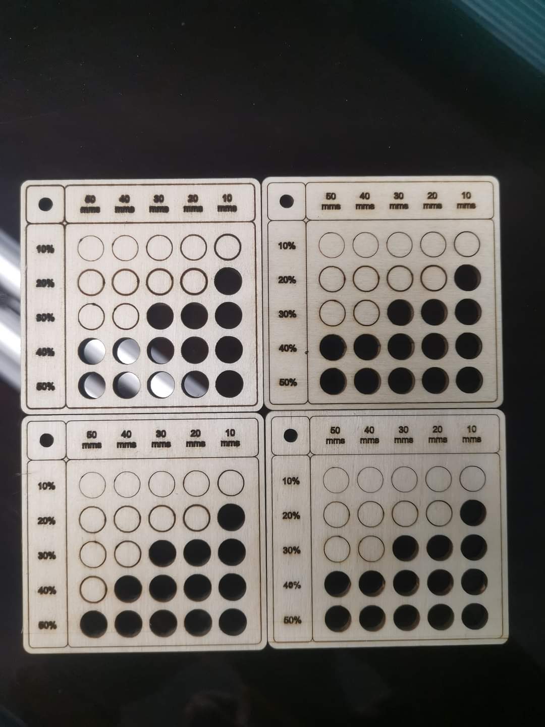
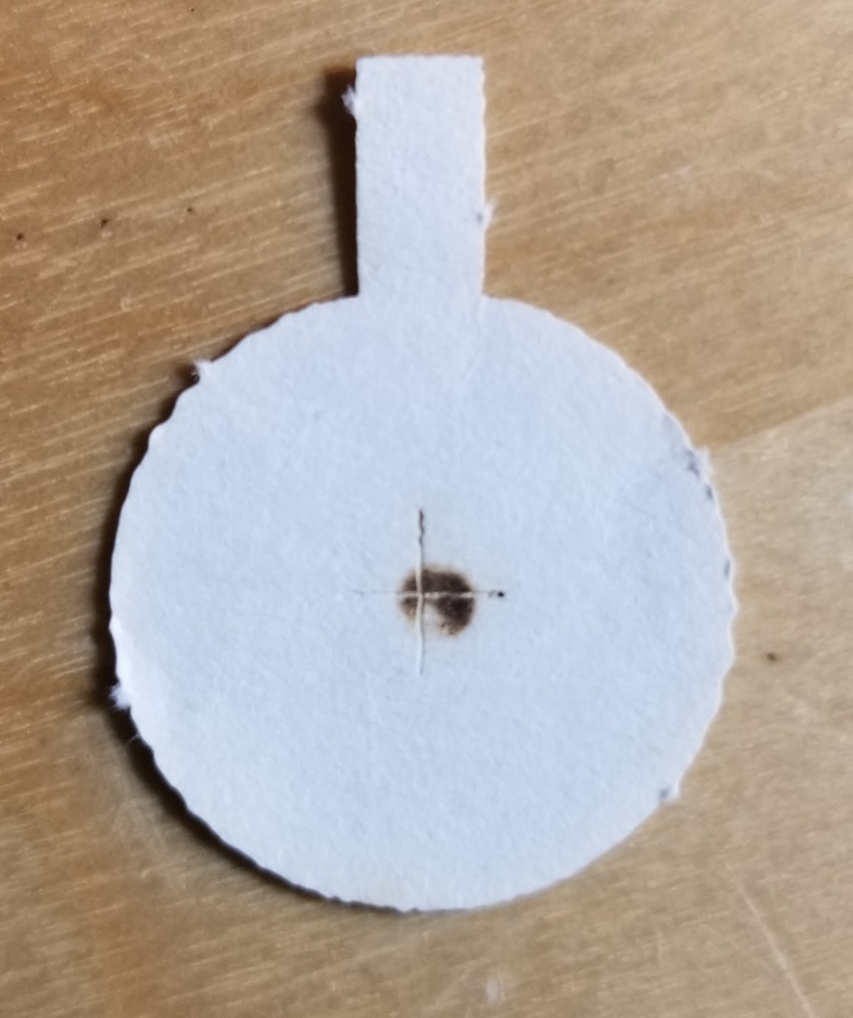
I made a test circle of 10mm in each corner with a speed of 150mm/s and 15% power.
The focus distance was set 4 times manualy so we can be sure its not a focus problem because the docus distance from nozzle was the exact same for each circle in every corner.
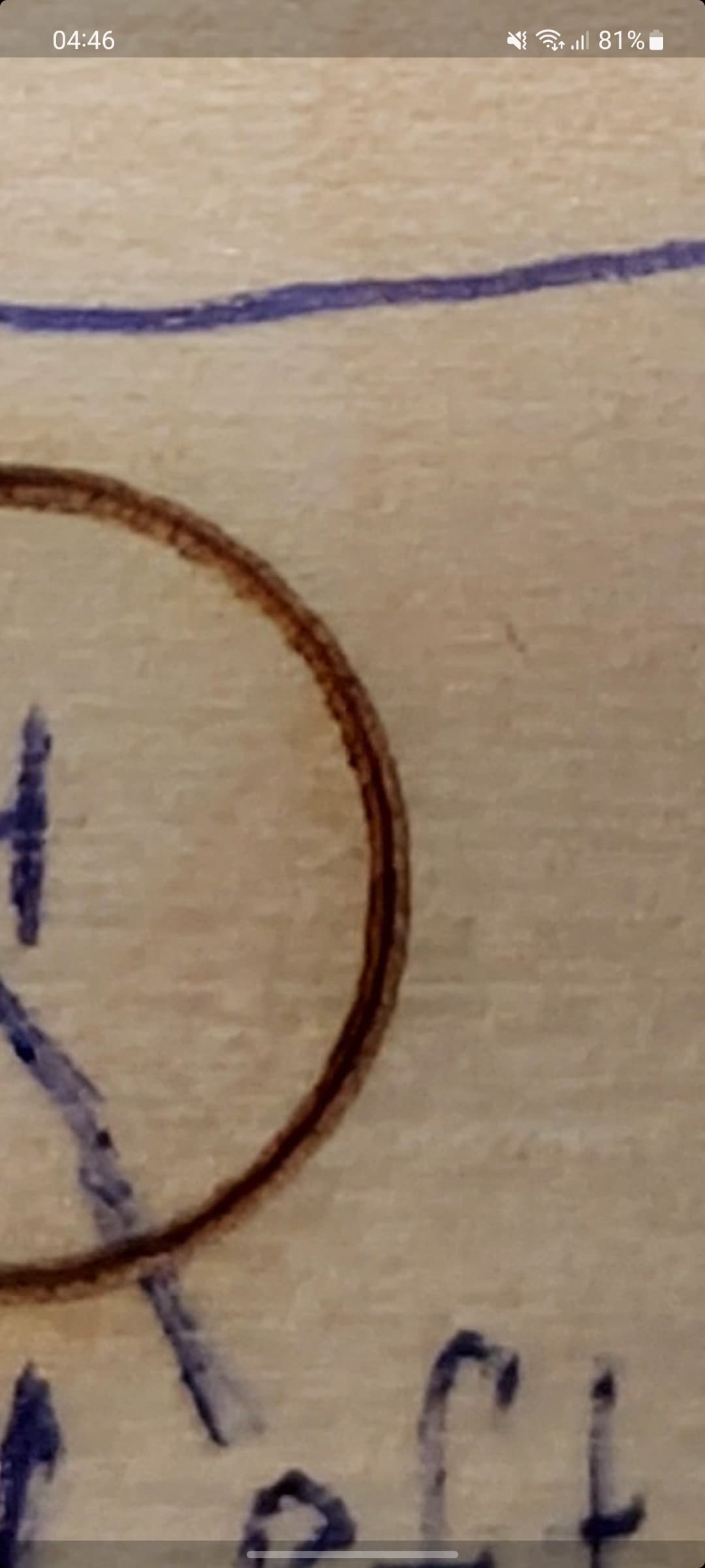
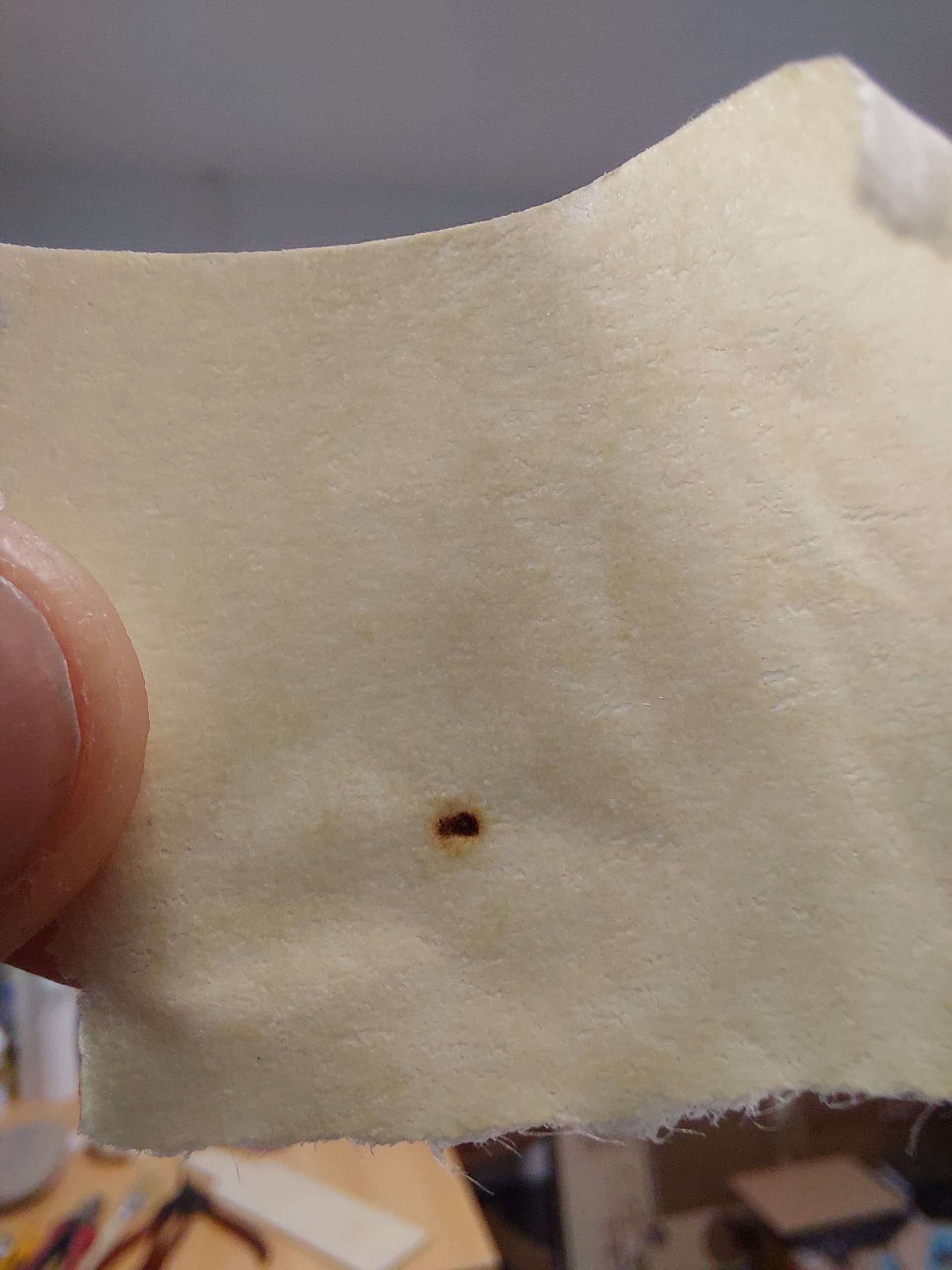
I dont know what causes those strange lines around it, it seems like in the middle of the circle there id the good line but i also get those strange outer lines. I need to know what can cause this but i just cant figure it out. I post some pictures so that you can see what i mean.
I really hope someone here can help me with it, otherwise i have to pay a few hundret bucks to a service technician in the hope he can help me but i really dont wanna spend so much money and then in the end he also cant fix it.
It appears to me like it’s out of focus, even going around one of the circles isn’t even across the burn area.
What does the beam look like at m1 (mirror 1)?
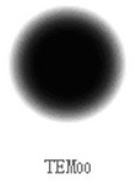
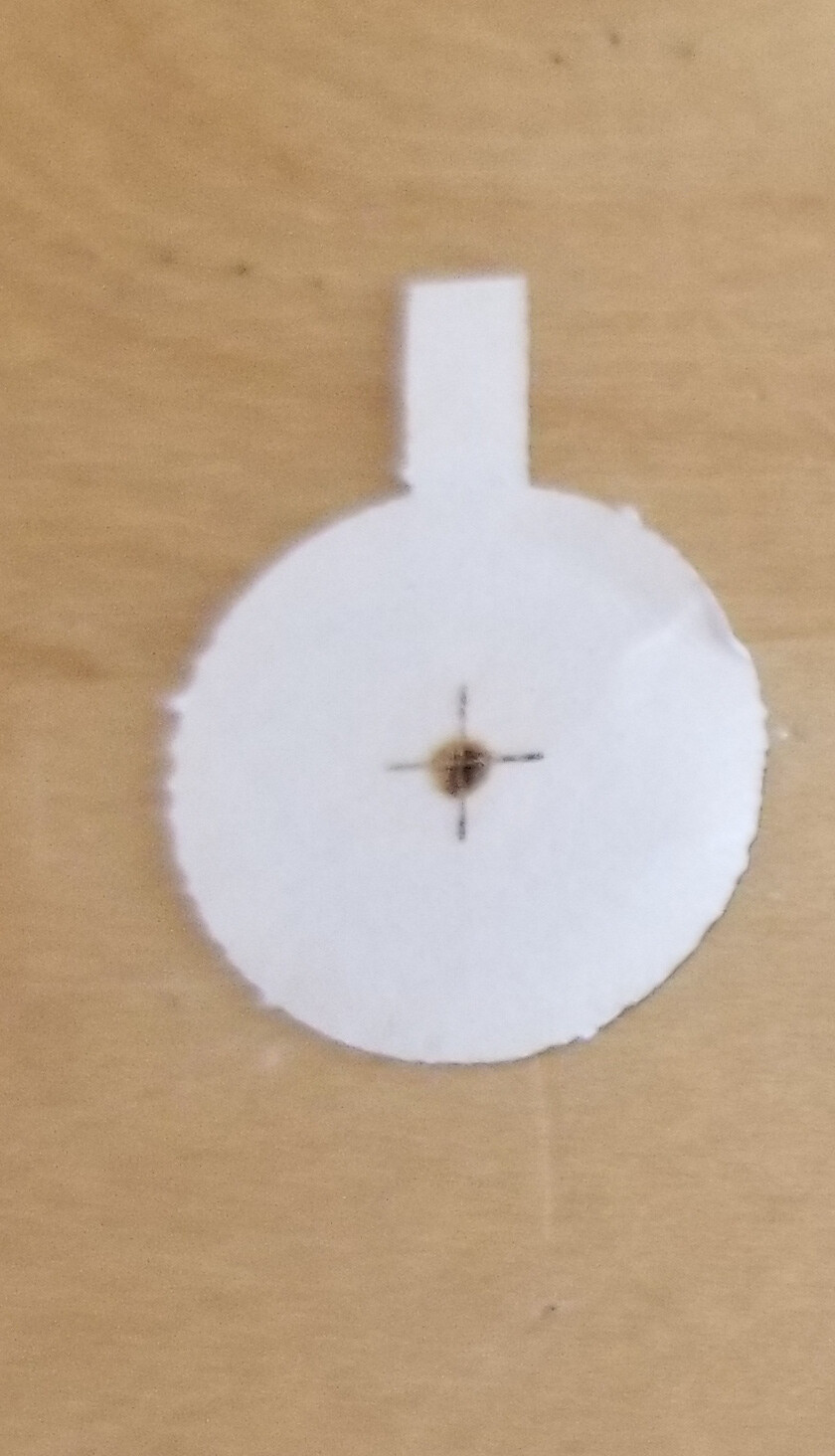
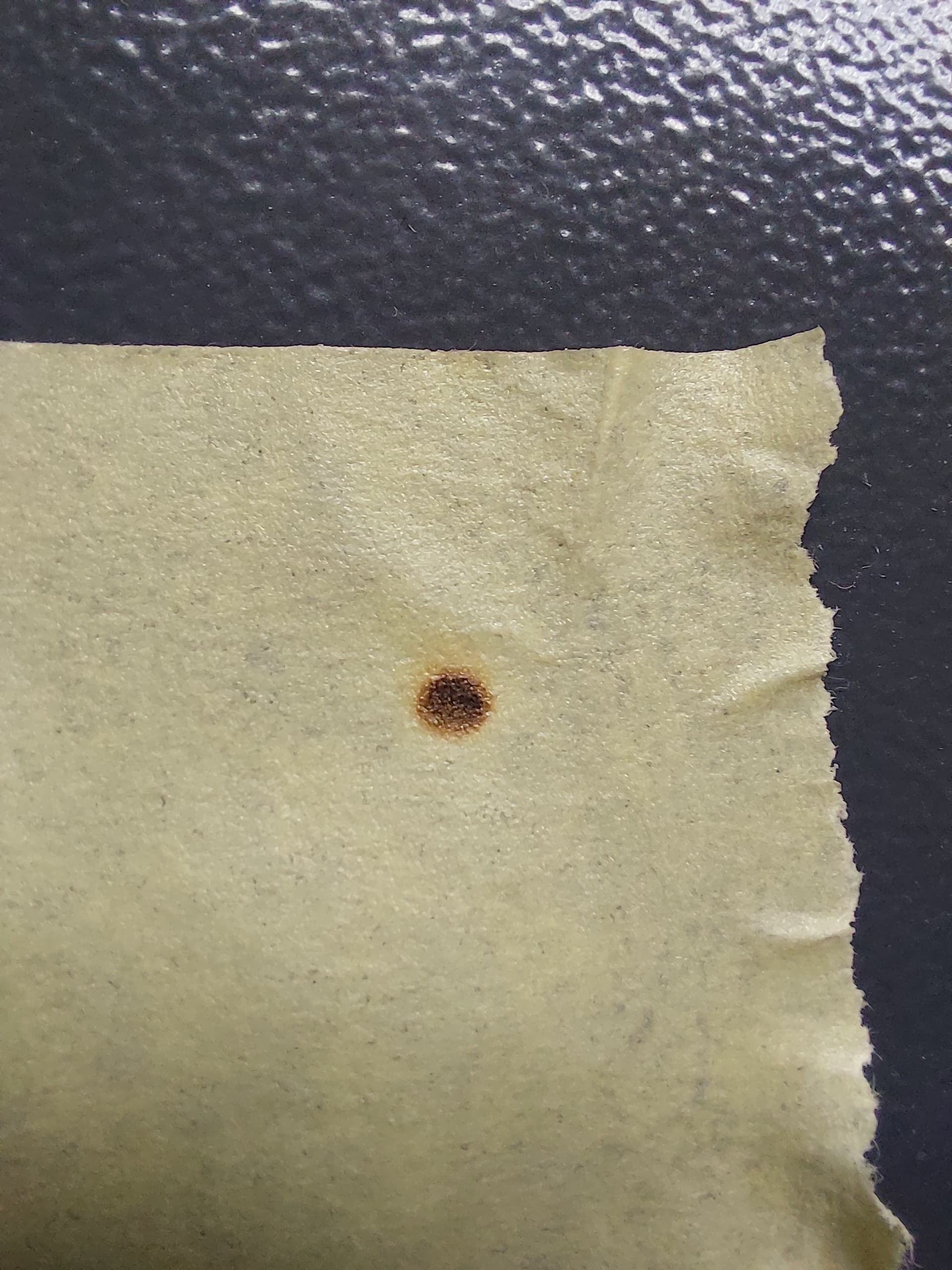
When you check the output of the tube, reference the burn mark against TEM0 resonance… This is a little burnt for me… I prefer a dark center and brown as it moves outward. But you get the general idea…
Measure the distance from lens to bed at each corner. Is it consistent? If not, you won’t be a the same focus. Relevel bed to correct. I’ll warn that this can be a painful process if your system is anything like mine.
Thanks for the help but as i wrote, i controlled the focus distance in every corner manualy with a piece i made for perfect focus distance before i made the circle. So yes the focus distance was the exact same in ever corner. Also the bed and the gantry are perfect in level. So as i said, the focus is not the problem, it was identical for every circle.
I would like to see your M1-M3 and nozzle target discs from the align test.
With what you describe, the most likely source of error is that the laser beam is not aligned correctly. I know you wrote that you have done everything and you have had the problem for half a year (which I don’t understand that you can live with), but as @jkwilborn writes, if the 3 points he mentions and your tube is TEMoo , is met/ok - you must have a fine result with very little decreasing power in the direction of M3 but still with the same fine focus.
@jkwilborn - is the TEMxx state a function of the tube output? or of the mirroring after output? If a function of the tube output - can it be user adjusted or does the tube need replacement?
I probably could learn all this directly by googling and reading… for hours. But I am hoping you have done all that and the answer is relatively straightforward.
When the tube lases, it resonates between the mirrors inside the tube. As the gasses degrade this resonance changes and the output beam changes. This is not user serviceable. Sorry… I had to change my tube out because of this… This is how mine started to degrade… It was dead center… It seems to move and a re-alignment is needed if you want to keep using it. As it got worse, the results on the outer corners varied.
Don’t know if that’s your case, but you have enough of the indicators to prompt me to ask.
The tubes output is what you want to see… this is before any mirrors… Here is a photo I sent you a couple weeks ago… it shows the target setup for TEM determination and the targets I cut out for use in alignment of the mirrors…
My mirrors are aligned perfect, from mirror 1 to mirror 2 i hit the same spot in near and far position and from mirror 2 to 3 i hit dead center in every corner. Today i also checked mirror 3 down to the nozzle, there the beam didnt come out in the middle, i aligned it so it gets out in center.
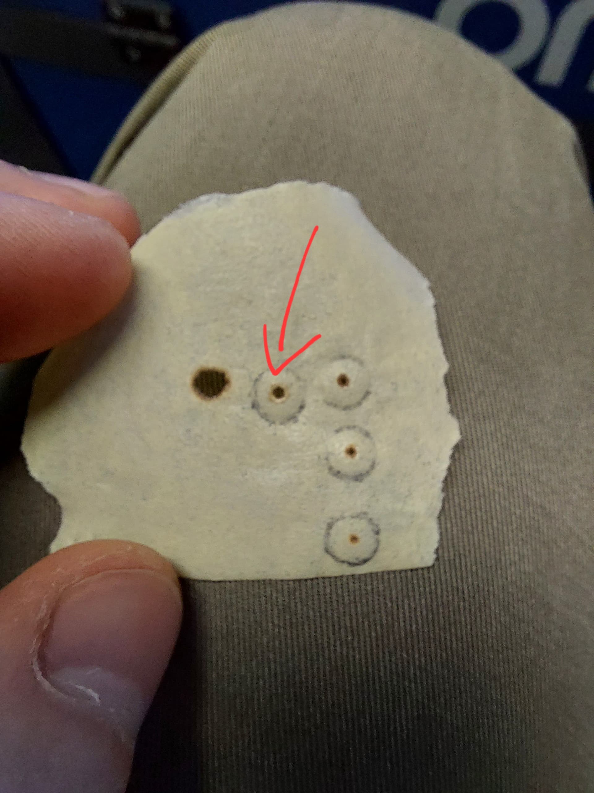
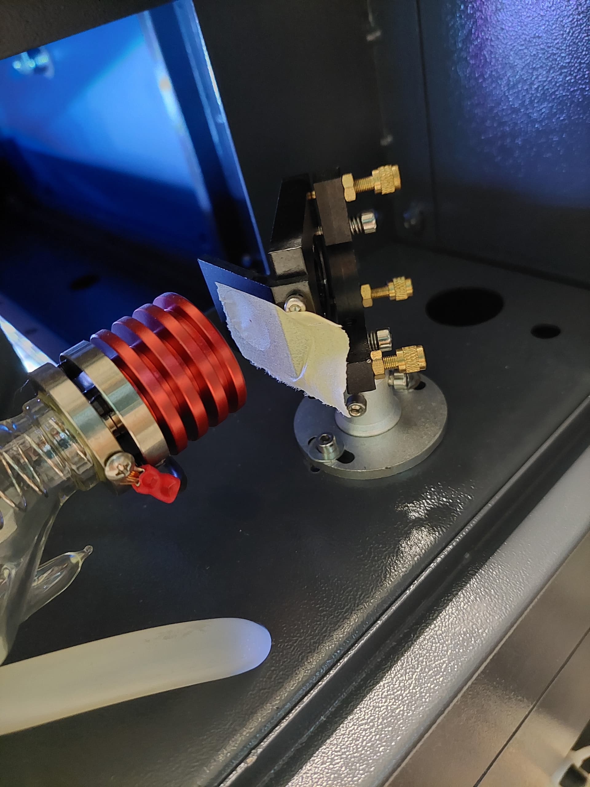
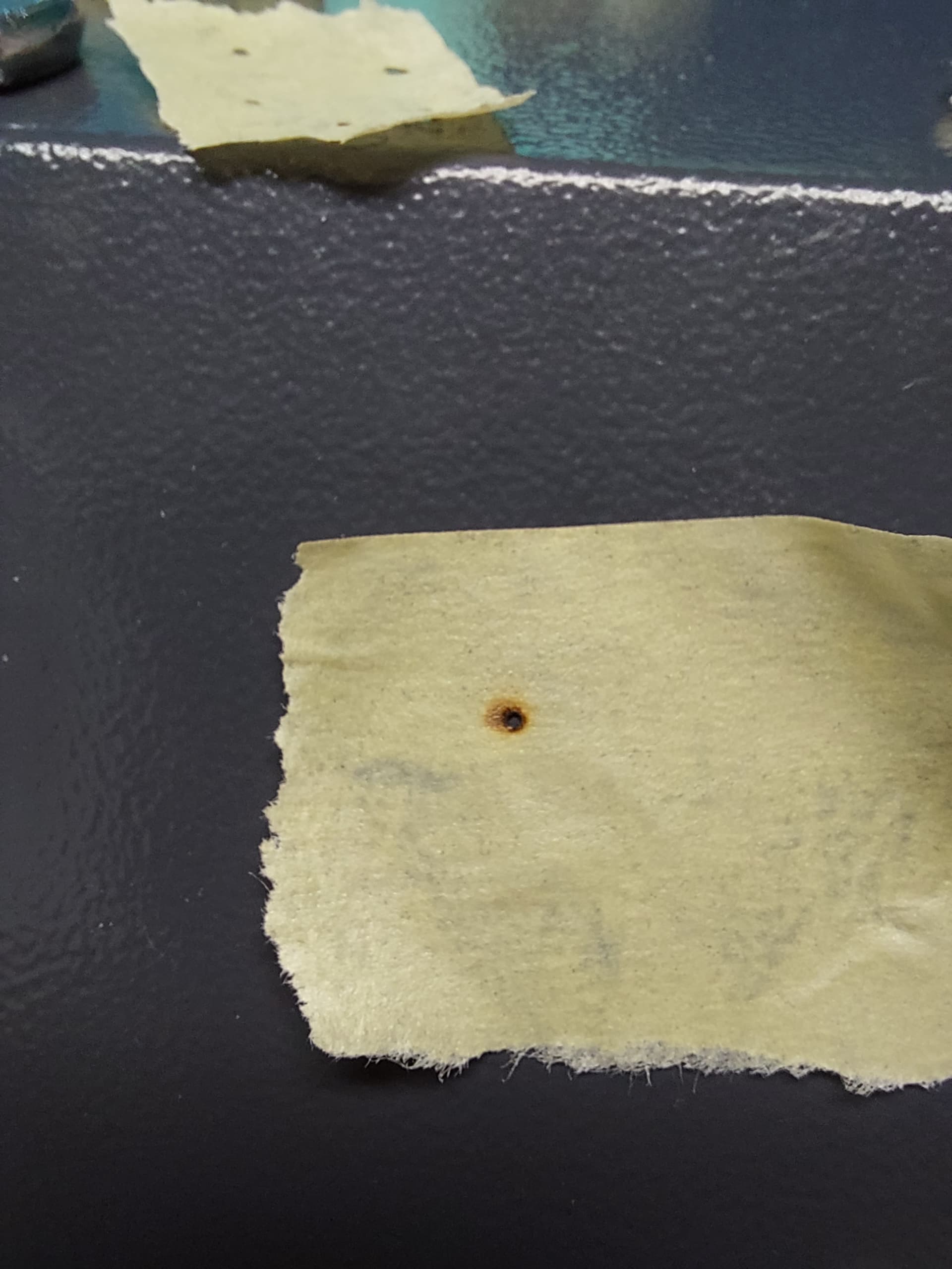
I post a picture now with tape on the nozzle, all those shots where made in a different corner, i marked the one in from the bad corner, as you can clearly see i get a way bigger dot or hole out direct of the nozzle in the bad corner. So its really strange to me, any explanaiton for this? Is it the laser tube that has a problem because i get a way bigger dot where the beam has the least way and a small nice dot where the beam travels the longest way?
Just read the last answer, should i make a test shot to mirror 1 with tape on it so we can see if its a problem because of the laser tube?
Watercolor paper… I used a manilla folder and found it seemed to need more ‘power’ to mark (longer on the pulse button). The marks seemed to be centered on the targets - but I did not get the clarity of strength that you are showing. I’m going to find some 'watercolor paper as you suggested in your earlier post.
Thanks for being so willing to share your knowledge -I sure do hope it’s not a new tube… yet!
We want a brown mark. A hole is totally useless as you’ve fried all the information.
Back off the power so it’s mostly brown.
It doesn’t look round either… it should be round, even over burnt…
This is an older target from an m2 alignment. It has two pulse strikes, one at long distance the other is the short distance… Notice the color…? It’s also not a hole.
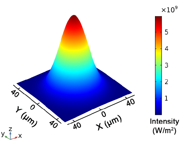
The illustrations in those references show that TEM00 mode is a simple Gaussian hump in all directions around the beam axis. The laser can operate in other TEM modes that distribute energy in different patterns, none of which are useful for laser cutting.
The mode is an inherent property of the tube / gases / mirrors, so external tweaks do not affect it. The machine’s alignment and focus can be perfect and the laser will still not cut properly, due to the incorrect distribution of energy within the beam.
That’s better and it isn’t looking good… Can you back off the power and get a real light mark…
You want to see the power distribution of the beam, sometimes referred to as power density… A perfect beam should have a Gaussian power curve to it, that you can see if the mark is not too dark…
With back of you mean i should place the tape on mirror 2 and move it to the front side of the laser so that the beam travels more distance to hit the tape?
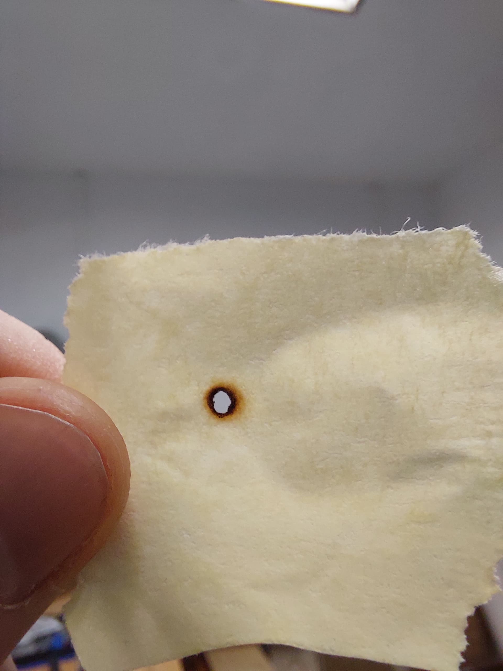
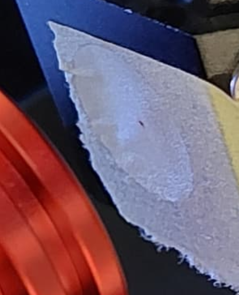
Thats how i do it, here another shot with even lower power (at 9%) but the dot is soo small i have to pulse a little bit longer and the i get a little hole into the tape.
Is this centered? From the photo, it looks like it’s off center. It might be fine, but I can’t really tell from the photo… I blew it up for a better view…
The dot itself, doesn’t look bad. I’m making the assumption that the uneven brown area around the shot is from burn debris.
The beam is pretty small for a 100W machine. Mine is larger and it’s half the size of yours. Most machines don’t want to lase below about 10% and this usually gets worse as the power increases. I’ve read many threads with 100W machines that owners claim won’t lase below 20%…
There is a range where the tube where it’s lasing, but not as designed … producing output, but not good output… I’d try increasing the power percentage and lowering the pulse duration. See if you get a more stable looking results.
What procedure do you use for alignment? Is it on a link we can see to follow you?