I think that’s true when you have Bidirectional turned on: the head goes this-a-way on one and that-a-way on the other.
The resampling will crush whatever you have into whatever you asked for, so an exact multiple doesn’t really matter. What does matter is not expecting any detail in the crushed pixels to magically remain in the resulting smear.
That’s my default, also suitable for pedagogic purposes ![]() , and pretty close to the truth for most lasers. The actual spot size depends on a myriad factors, including:
, and pretty close to the truth for most lasers. The actual spot size depends on a myriad factors, including:
- power (% of maximum)
- speed
- material
- surface finish
- temperature
- tube / diode age
- moon phase
The engraving spot size will be about half the kerf width while cutting, because the beam is not vaporizing bulk material.
When you really care, check your assumptions in a small corner of something priceless, before wrecking the rest of it.
When you’re removing a coating, you can waste a lot of time removing the removed stuff over and over again. The substrate looks pretty much the same after the first pass, but if you enjoy watching CNC machinery at work (*), go for it. ![]()
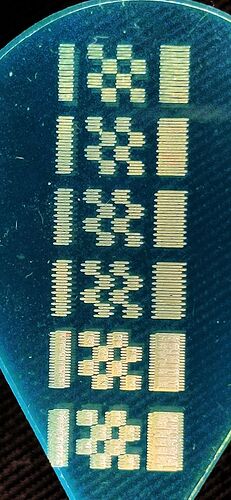
On a uniform material, more overlap means more energy, so setting the proper spacing matters. Here’s an acrylic test target of 1 mm squares, the top four at 0.2 mm spacing to separate the lines and the bottom two at 0.1 mm), run at various speeds to measure Scan Offset spacings:
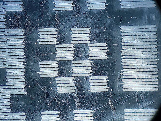
A closer look suggests the proper line spacing would be 0.15 mm, while revealing some spurious dots:
Spaced closer than that, though, would let successive passes dig a deeper ditch in the plastic.
Burn away!
(*) Many people do, as witness Youtube. I admit to an unhealthy fascination with my first 3D printer, but I’m better now. ![]()

