What size image when designing for an engraving?

So i’ve started to learn how to use Illustrator and Lightburn properly. A few days ago I tried designing a custom image to be engraved onto a rock for my baby girl. It’s a small enough rock that only a 30mm x 30mm image was required, so I started to design an image of that size. I was able to conjure up some kind of image in Illustrator; i wasn’t happy with it, but it was enough for me to start using LB. After importing it into LB, I used the image trace feature, and it got me thinking ----- this sucks.

First question: if I need a 30mm x 30mm image for an engraving should I design a 300mm x 300mm image and then size it down for engraving? Im thinking yes. If the answer is in fact yes, how much larger should the image be as a rule of thumb?

Second question: I imported a black and white BMP file. Do I need to use the trace feature on LB to burn that black and white BMP?

Third question: I made a BMP image because when I exported my image as a SVG using illustrator and imported it into LB, the the text font in LB wasn’t the same as it was in Illustrator. Why did that happen? Does LB need the same font? That doesn’t make sense because isnt Illustrator exporting the traces only of my image?

Thanks.

  1. In Edit>Settings>General Settings>File Settings, there is an option for LightBurn to import SVG raster files in the 72 DPI resolution which is best when importing SVG’s from Illustrator.

  2. You can directly engrave from an image, trace is not necessary, see the docs here, if your image is very simple black and white with no greys the “Threshold” image mode works very well.

  3. I’m not an Illustrator expert, but I believe there is an option when exporting artwork to SVG to export any fonts as outlines.

Amazing. Thanks you so much I will try all this. Thank you.

Probably not necessary, because working on a larger image will make you think the image has more pixels than the laser engraving process can deliver.

Instead, set the image size and resolution (DPI) to match the engraved result, then design within those limits. If you intend to engrave at 01 mm/pixel = 254 DPI, than a 30 mm image will have only 300 pixels along each axis.

Starting with a 300 mm image at 254 DPI lets you think you have 3000×3000 pixels to design with, but the final result will be disappointing: 90% of the pixels must vanish on the way to the laser beam and the remaining 10% won’t be the ones you care about.

Also, LightBurn resamples the image to produce square pixels based on the raster scan line spacing. A 300×300 pixel designed at 254 DPI, then engraved with a 127 DPI = 0.2 mm line spacing becomes a 150×150 pixel image: half of the pixels vanish.

I found that out the hard way:

Various dithering algorithms interact with the image in interesting & amusing ways, so experimentation is always in order, but the fundamental limits on the output remain.

I have to wrap my head around this. I was burning mirrors a bit ago and put it on hold because I was getting frustrated. I was engraving 4" and 10 mirrors. I started with the 4" mirror and engraved an image at some DPI like 300 or so and It came out great. I went to do a 10" mirror with another image at the same DPI and I even tried a higher DPI and it came out horrible. It turned out that I needed to drastically lower the DPI to get the same result.

Why is that? It’s been awhile since Ive done it and ive come to the point where im going to try again. I felt like I was so close to understanding it but it seemed like I was missing something.

I don’t understand why I would need to change the dots-per-inch based on the size of the image. I mean I do but I don’t.

If I engrave an image that’s 1 square inch at 254DPI it may look pixelated. but if I do an image that’s 300 square inches at the same DPI it wont look pixelated because if you stand back a little you’re seeing more pixels. It will look as pixelated if you look closely enough though.

If I remember correctly, I was engraving text, circuit board traces etc at 0.025mm line intervals which is 1016 lines per inch, which is not what I was using to engrave photos on mirrors. I think I was working with something alone the lines of 300dpi or so for the 4" mirror and maybe 80dpi for the 10" mirror.

What is Lightburn doing that I need to change the DPI depending on the size of the engraving? Are there any formulas I can use to determine the DPI?

The basic limitation comes from the focused laser spot size: about 0.1 mm.

LightBurn assumes a square spot, which is reasonable for a round (“gaussian”) CO₂ laser spot, plausible for the typical rectangular-ish diode laser spot, and pretty good for the newer compressed-spot diode lasers (when they work as advertised, which is not always a good assumption).

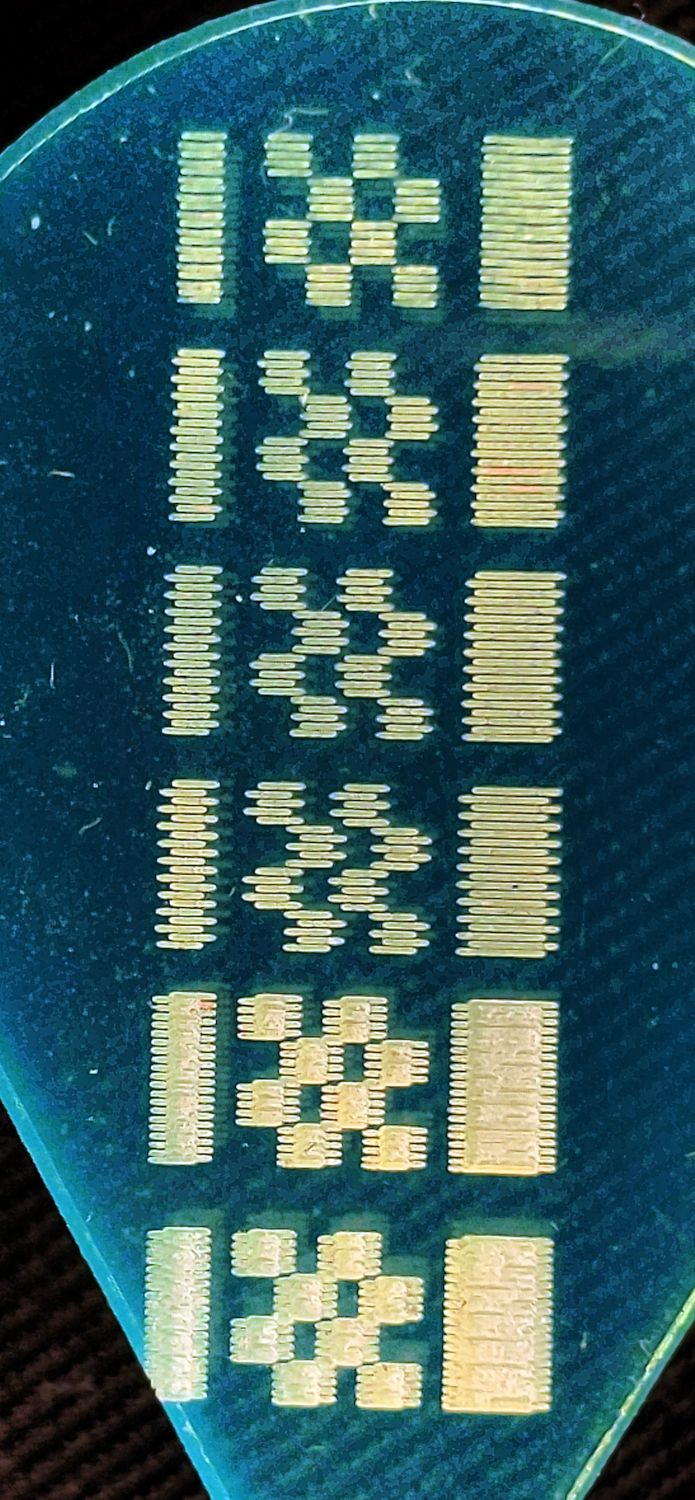
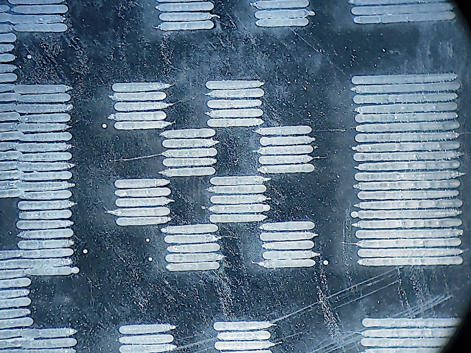
Engraving with adjacent scans spaced 0.1 mm apart ensures complete coverage of the surface. Each scan line is 1 pixel tall, so the Y axis spacing is 1 pixel / 0.1 mm = 10 pixel / mm = 254 DPI.

Engraving the lines closer together (higher DPI) will change the surface texture or deepen the engraving, but cannot produce “more detail”. Engraving farther apart (lower DPI) will produce visible gaps between the passes, which may or may not be desirable depending on the desired result.

That DPI value applies to an image scaled to match the physical size of the engraved pattern. If the engraved pattern is:

  • 100 mm on a side, then it has 1000 pixels on each side
  • 10 mm on a side, then it has 100 pixels on each side

Which is why the actual / physical / engraved size determines both the image size and its “resolution”.

Suppose you start by drawing a 1000×1000 image at the usual 300 DPI, then engrave it into a 10×10 mm square on the surface at 254 DPI. The engraved square must have 254 scan lines per inch = 0.1 mm/scan along the Y direction and therefore will have 254 dots/inch along the X direction. Because it must be 10 mm on each side, it will have only 100 dots along each side.

LightBurn must resample the as-drawn image to produce the physical values, so it will apply some algorithm to reduce 1000 input pixels to 100 output pixels along each side. Typically this happens in a square region, so think of it as mashing adjacent 10×10 pixel input squares into a single output pixel: each output pixel represents the average of 100 input pixels.

You can specify the mashing (“dithering”) algorithm, some of which work better with even larger images, but the result must produce the physical dot pattern actually sent to the laser.

For noncritical images, say puppies on wood planks, none of that matters. When you care about surface finish, perhaps to remove a mirror’s backing and leave a smooth surface, precise control of the image data going into each dot matters.

You might even go so far as to size the input image to exactly match the output image, then have LightBurn send it to the laser in Passthrough mode, so each input pixel produces one output dot.

That’s as I understand it, anyway … :grin:

2 Likes

AMAZING REPLY! Thanks you so much.

I believe I understand now. I don’t know what I was thinking before. LOL.

So ---- I read what you wrote many times, making sure I completely understand what you’re saying. I also opened LB, set my line spacing to 0.1mm, created a 1mm square and used the preview feature to better visualize it.

Just to summarize everything —

1: My engraving area needs to be a multiple of the (line interval * 2) for an even number of scans.

2: My image needs to be a multiple of the engraving area, or vice versa, for proper resampling.

Also, if my focal point is much smaller than the default 0.1mm I may need to adjust that value. I have a digital scope. I think im going to do some tests and zoom in to see the scan lines. I’m have been engraving vector images at a 0.025mm line interval and it seems to work great. I’m wondering if im overlapping my scan lines. I mean, for engraving something super tiny and intricate, it was necessary. I was creating circuit boards with tiny traces/ spacing. It came out much better when I ran the laser at a much lower line interval. The larger line interval was removing to much copper. The traces were much thinner than they were supposed to be. If im engraving logos etc, running the line interval that small will be a waste of time, as long as im not experiencing gaps between my scans.

Thank you so much.

I think that’s true when you have Bidirectional turned on: the head goes this-a-way on one and that-a-way on the other.

The resampling will crush whatever you have into whatever you asked for, so an exact multiple doesn’t really matter. What does matter is not expecting any detail in the crushed pixels to magically remain in the resulting smear.

That’s my default, also suitable for pedagogic purposes :grin:, and pretty close to the truth for most lasers. The actual spot size depends on a myriad factors, including:

  • power (% of maximum)
  • speed
  • material
  • surface finish
  • temperature
  • tube / diode age
  • moon phase

The engraving spot size will be about half the kerf width while cutting, because the beam is not vaporizing bulk material.

When you really care, check your assumptions in a small corner of something priceless, before wrecking the rest of it.

When you’re removing a coating, you can waste a lot of time removing the removed stuff over and over again. The substrate looks pretty much the same after the first pass, but if you enjoy watching CNC machinery at work (*), go for it. :grin:

On a uniform material, more overlap means more energy, so setting the proper spacing matters. Here’s an acrylic test target of 1 mm squares, the top four at 0.2 mm spacing to separate the lines and the bottom two at 0.1 mm), run at various speeds to measure Scan Offset spacings:

A closer look suggests the proper line spacing would be 0.15 mm, while revealing some spurious dots:

Spaced closer than that, though, would let successive passes dig a deeper ditch in the plastic.

Burn away!

(*) Many people do, as witness Youtube. I admit to an unhealthy fascination with my first 3D printer, but I’m better now. :worried:

Ok. I have a question regarding the drawing’s 300DPI and the engravings 254DPI. These values do not need to match? They don’t need to or for best results they should?

What I’m thinking is that Illustrator exports BMPs at 300dpi, which means that if I want to know what size images I can draw I would have to calculate the multiple by simply: 300px / 25.4mm = ~11.8px/mm. This means that if I want to engrave an area that’s 240mm^2, i’d need an image that’s either 236mm^2 or 247.8mm^2.

Am I right? What would happen if I had illustrator output an image that’s 300dpi and I calculated that image’s area using 254dpi? I would lose some of the pixels? I mean I’m losing some pixels regardless even though I used 300dpi for the calculation, because the result was a floating point value.

Thanks for your help sir.

Thanks you for the explanation. Very cool stuff. I believe we posted at the same time, so my last post(other than this one) isn’t a reply to your last post.

The only thing that matters is the number of pixels, because that’s what goes into the Procrustean conversion.

It’s convenient to make the drawing (input) DPI match the engraving (output = physical) DPI (= scans/inch), because then the drawing will render at the physical size, assuming it has the same number of pixels. You can always zoom in to work at the pixel level or zoom out to work on the overall drawing, because that just changes the size as seen on the screen.

So you can set the DPI to match or ignore it completely.

If the input drawing has more pixels on a side than the output engraving, then the ratio will generally be a float. The square of that ratio gives you an idea of the overall compression.

As before, starting with a drawing 1000 pixels on a side that you intend to engrave at 0.1 pixel/line = 10 pixels/mm means the drawing will be 100 mm on a side. If you mash it into a 10 mm square, then each side has 100 pixels and each output pixel represents, in some sense, the average of 100 input pixels.

The input DPI has no effect on the result, because it’s pixels all the way down.

If you have a choice, PNG format is better than BMP, because it uses lossless compression well-suited for line art and filled areas. You’ll get smaller files, not that size matters these days, and trivially faster load /save times. Same pixels in both cases.

If you’re doing pictures (that puppy-on-a-plank thing), then you may as well use JPG files with lossy compression, because none of this pixel-fiddling nonsense makes any difference.

Thanks so much man. You’re a huge help. :+1:

Im a beginner on Lightburn but have many years experience in Illustrator.
*This is not to correct anyone but contribute to general knowledge.
First thing to remember is illustrator is a Vector based program primarily.
Therefore you can zoom in infinitely on screen and work on a huge pasteboard with a small image until you rasterize (Export/ Save as).
It is good practice to work at actual size and adjust your pasteboard to suit.
That way dimensions are set and you are not accidentally generating huge files on conversion.
As far as resolution consider it as a “Volume” not just a dimension. ie: 300x300mm@300dpi = File size. Same data if you spread it thin over a large area or deep over a tiny area.
Commonly people Raster at higher DPI and the RIP (Raster Image Processor) has to resample to the output resolution.
That is where the experts here have beautifully explained the lightburn interpretation of pixel data/ dithering etc.
Its all the same process as laser image setters have been using for decades in printing.

So I finally wrapped my head around all this, but i have a question you might be able to answer. I have this photo ive been using to practice. Last night i cropped the photo so its 2400x2400 pixels. I exported it as a jpeg at 254dpi and the image was huge! I found out why illustrator is doing that, via a google search, but im still wondering why its doing that. If i use 72dpi its remains 2400x2400. I dont want 72dpi. If i specify that the general units is mm, and then i can say i want 240mmx240mm @ 254dpi and the size of the image of the image will remain. I switched to pixels because i thought it would be nice to easily see how many pixels im working with. I switched back to mm and it works. Im a CAD dude, this vector imaging is something completely different, or maybe its just illustrator.

I used imag-r.com to process that image for lasering, because i know a lot of people do it this way. So, i had this site do it all for me. I cropped it, resized it, and specifed the dpi. When i loaded it into LB, i xouod finally see see what pass-thru is for. I imported the same photo but from illustrator and the preview looked exactly the same as the pass-thru with the imag-r photo. Im on the riggt track now.

Because that’s what you asked for: 2400 pixels / 254 DPI gives you an image 9.4 inches on a side.

I think you have confused two different things:

  • exporting a fixed image at a new DPI setting
  • resizing an image at a given DPI

The first maintains the same number of pixels, so the as-printed size must change to match the new DPI.

The second changes the number of pixels to fit the image within the new size at the same DPI.

You can do both at once, but proceeding one at a time reduces the number of amusing results.

Remember this applies to raster images, not vector images.

When you convert a vector to a raster, you specify the output DPI and the image is sized to fit the vector’s dimensions.

For example: start with a vector square 10 mm on each side, then export it to a raster PNG image:

  • 254 DPI = 0.1 mm/pixel → a square 10 mm and 100 dots on each side.

  • 508 DPI = 0.05 mm/pixel → a square 10 mm and 200 dots on each side

The drawing size, the physical size, the number of dots, and the dots/inch are all interrelated: you can’t choose them independently. On the upside, once you see how they interrelate, then knowing what you have lets you get what you want.

So after exporting my 2400x2400 pixel image @ 254dpi, the image ended up being 8467x8467 pixels. Based on what you showed me here right now, my image was 2400/72=33.3inches. Its was big. The 8467 = 254(2400/72). I know i exported it @ 254dpi. I googled this and thats how i found out how its sizing my photos. I dont know what im missing in illustrator, maybe some settings i missed, but using mm as the general unit of measure and exporting the image @254dpi seems to work. The image info windows provides says 2400x2400, which is 240mm with 10 pixels per 10mm gives 2400. This is right? I dont size stuff up as pixels when laying something out to be lasered on material, so leaving it as mm makes sense, but having it as pixels is nice when sizing images etc to be absolutely sure i have the right number of pixels.

Not having Illustrator, I’m clueless as to which combinations of controls you have available, but the fundamentals remain in effect.

You can specify only two of:

  • dots per inch or mm
  • image size in pixels
  • physical size in inch or mm

Setting any two determines the third.

I cannot say exactly how you specify those values in Illustrator or what assumptions it forces on you, but some experimentation ought to show you how it handles your input values.

I’m pretty sure I have a basic misunderstanding of how Illustrator presents its information to you, but the 72 in:

8467 = 254(2400/72)

… comes into play only when you want to export the drawing to a physical medium.

Assuming the vector image uses 72 DPI as the default, you were drawing the image with vectors around 2400 pixel / 72 DPI = 33 inches. That’s your drawing scale: “I want this image to be a yard across!” without thinking of the actual dots.

If you drew with different length vectors, you could make a drawing a foot / inch / mile / furlong across.

Exporting a 33 inch vector at 254 DPI gives you the 33 inch * 254 DPI = 8467 pixel image you got. Engraving that image at 254 DPI will, indeed make it 33 inches across.

If you resized the original vector drawing to be, say, 1/3 its original size, it would be 11 inches on a side. Exporting that at 254 DPI would produce a pixel image 2794 pixels across and engraving it at 254 DPI would produce an 11 inch image.

Resize the original image by 1/33 to make it 1.1 inch on a side. The same 254 DPI export will give you a 279 pixel image and a 1.1 inch engraving.

Try those and see what happens: amusement may ensue!

So i havent even begun drawing any vector images yet. I merely just imported a 720x 830 something image to be cropped and resized. Its just a raster image. Im gonna keep playing around with it and see what happens.

1 Like

That’s yet another variation: you start with a raster image, manipulate it with a vector editor, then export the result as a raster image.

There are too many layers of conversion for me to make any further suggestions.

Although it’s not what you want to hear, IMO using a raster graphics program to edit raster images will dramatically improve your quality of life.

For my simple needs, The GIMP works fine; you’ll find plenty of other programs out there.

Ok. Thanks.