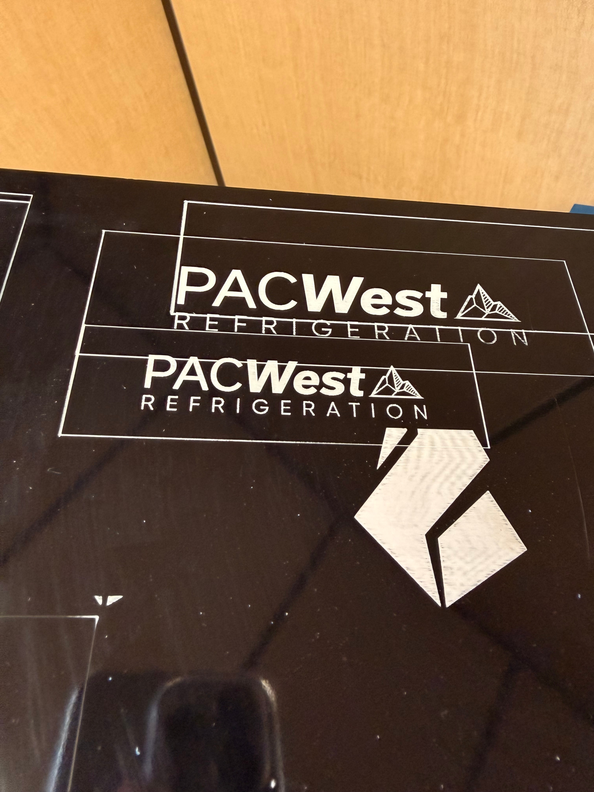
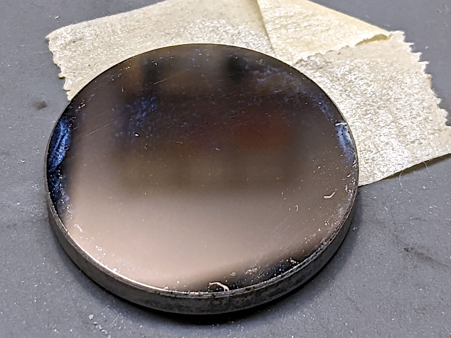
I’m completely new to laser engraving, or CO2 lasering all-together. My company purchased a LightObject Ranger 3 laser, because I did some research, and it seemed to be a good company, and a good laser. I was having some trouble at first and getting varied results, but eventually I thought I had a good setting on LB (results are black photo). I used 285 spd, 85 pwr, 0.100 interval.
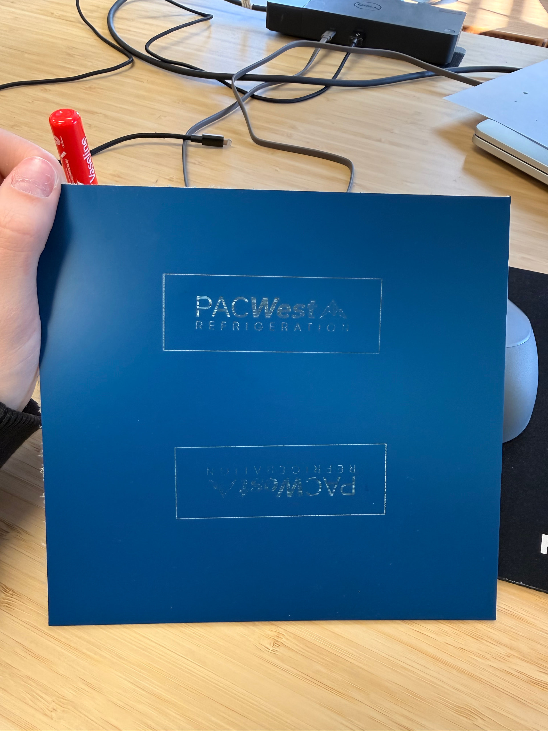
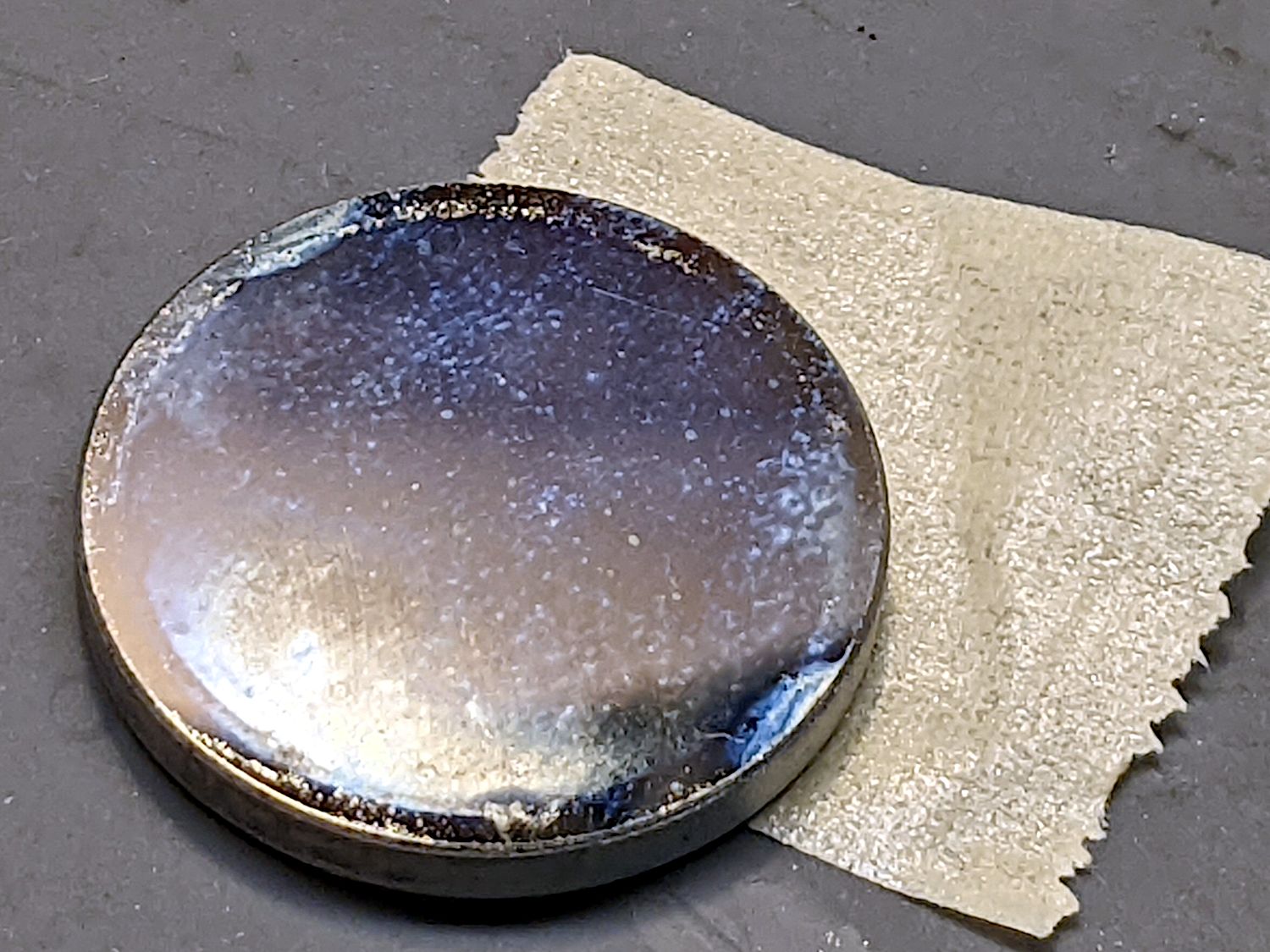
We were still continuing to play with the settings on LB to see, eventually our results went back to square one and stayed there (blue photo). I’ve done some research, and I cleaned all the mirrors and lenses with rubbing alcohol and q-tips (there was a lot of buildup on the lens) but it hasn’t changed my results at all. I’m wondering if it is an alignment issue. I’ve tried watching tutorials and I’m worried that I will mess it up even more so I want to be 100% sure it’s that.
There’s very minimal info/tutorials for the Ranger 3 laser and I’m just wondering if anyone has any advice or idea what the issue could be?
You need to check your alignment and it won’t ruin anything. Another possible error is the height of the machine bed over the entire area in relation to the nozzle. Make a list and proceed systematically in troubleshooting. Ask us if you run into something along the way that you don’t understand or are in doubt about.
I mean no offense but your design right smack in the middle of your material suggests you aren’t familiar with the 3 start from positions. It reminds me of my sewing class days when students would cut a piece of fabric out of the center of a square instead of simply using the edge!
It looks like you are using two different materials, one shiny and one matte. Where did this material come from? Did the manufacturer provide laser settings?
Have you tried increasing the power and decreasing the speed? I would just laser a little filled mode box in the corner of the blue material until you find that perfect combo to get the results you’re after.
I’ve never heard of your laser model either, thanks for creating this post! Glad to hear you’re maintaining your equipment. What are your concerns regarding checking the alignment?
The height of the laser in relation to the material is important too, when you move your laser head around, is the distance the same between the bed and the laser?
I assume and the @jsure can confirm, it’s this one?
It’s odd they never mention the power that I saw.. I bought my last tube from these people… Nicest I’ve worked with, and based in the USA… I think they use Chinese parts, but they know how it works.
If it’s relatively new, it’s nice to keep in contact with the vendor if you have issues. Most of us have Ruida controller, but the Trocen is also nice.
Do you know the power this outputs? 85% power seems like a lot for what your doing as this appears to be at least a 50W machine.
It will. Eventually this debris will heat up enough to crack the lens. This is the purpose of an air assist. It’s main purpose is to keep the debris out of the lens, but can really help with cutting wood.
The advertisement says nothing about air assist and I don’t really know that machine or controller very well. Here’s the AWC7813 manual if you need it..
Can you tell us how long the tube is and what current it’s drawing at 85% power?
The laser tube is 75-watts and it operates at AC110V 60Hz.
Everyone seems to tell me that, but even when I was getting better results than currently, anything below 80-82.5 power didn’t engrave very well and it ended up being similar to what I’m getting right now.
I’m not sure where the black material came from, but it’s almost identical to the matte just different finishes. The blue is Trolase plastic and it’s what we’re needing to use to make limacoids (the whole premise of buying the laser). I don’t think the manufacturer provided settings. I wasn’t familiar with the 3 start positions but I appreciate the link because it did help! I am engraving the material exactly 6mm away from the laser.
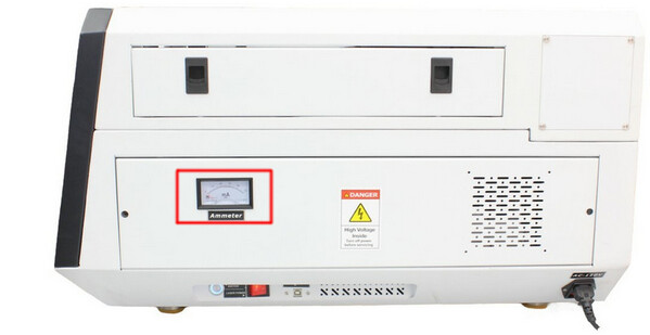
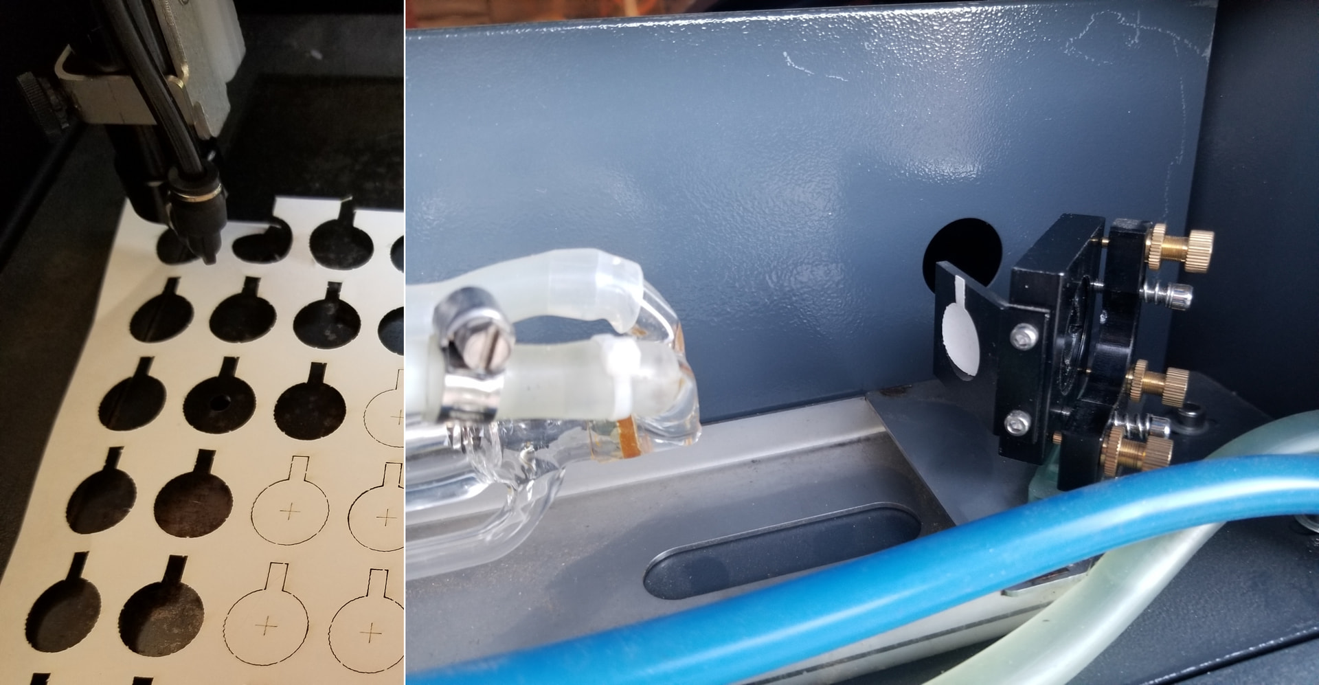
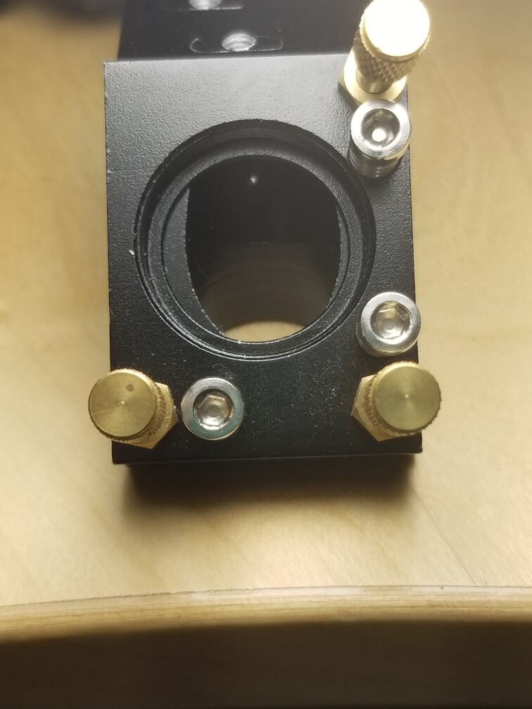
This looks like a mA meter (red box) on the right hand side, do you have this?
It’s the best indicator to tell you how well your tube is operating, at least electrically.
Tell us what material you’re lasing. A link to an item is better than us guessing. Do that if possible.
Each photo looks like a different material which usually means different settings on the machine.
Many of us have aligned our machine enough times we are not scared when we need to do it. The first few times can be a brain twister.
I realign mine when I change something in the optical path before the lens. I have a few different lenses and tubes, so I switch them a lot. Unless I change a tube or mirror I usually don’t worry about it going out of alignment.
Generally you can’t hurt it, but I’ve seen people learning how to do this break the machine, I’m one of them.
Took an eyeball of your materials and it’s basically acrylic. The recommended engraving depth is 0.003” or about 0.076mm. Even 0.1mm isn’t very deep especially for the material using a 75W machine.
Usually Trotec has a pdf that will have suggested start settings for testing… Didn’t see any, but I wasn’t logged into the site.
I could likely do that with 1/2 or less power than you are using, with my 40W co2.
Do you have a source file that’s not proprietary, you don’t mind uploading for all of us to read? It would be nice to see how you set it up. I don’t really see anything in your two photos that I can really make out that means much to me now.
Since you seem to have plenty of power and you’re using a lot, at >80%, I’m suspicious the cause may be elsewhere…
The fact that it’s not charring the material says there’s something wrong with the optics: either the tube isn’t generating the proper beam shape or the beam isn’t making it to the material.
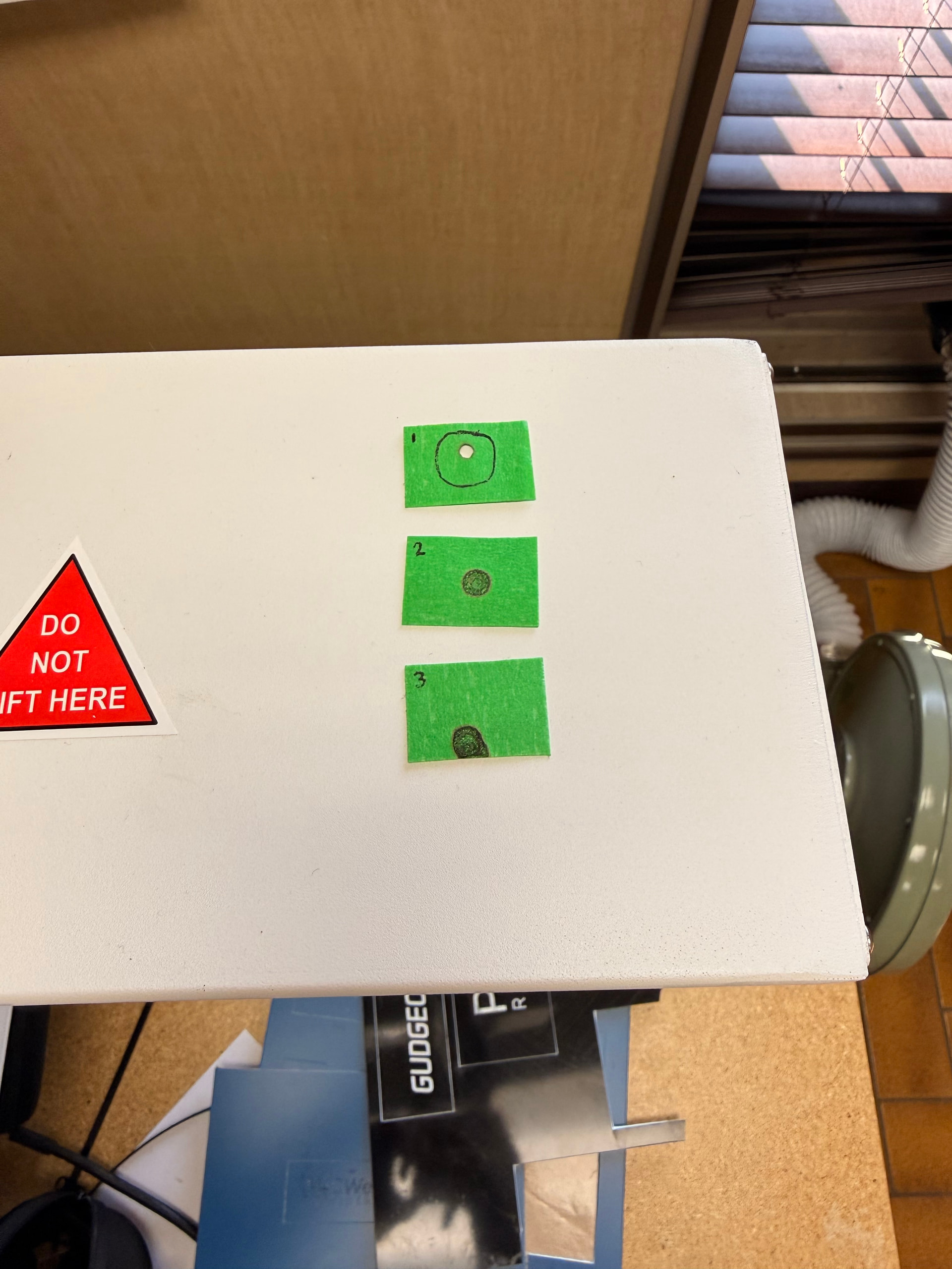
Start by cutting some one-inch squares from a manila file folder or similar heavy paper. Tape a square on the entrance to Mirror 1, which is the one in the back of the machine just beyond the end of the laser tube. I made round targets, but there are few style points for this task:
The controller on the machine has a button labeled Pulse (or something similar) to fire the laser; as always, with the water chiller running and the lid down.
Press the Pulse button quickly, open the lid, and see what happened to the target paper. What we need is a brown scorch, not a crispy hole burned through:
If the briefest pulse you can manage blows through the paper, that may be good news. If it’s weak, repeat the pulse enough to make a visible mark.
You’ll do that at all three mirrors and all three spots should be dead-center in the middle of the aperture.
Take some pictures for show-n-tell.
That tells you either the assist air wasn’t turned on or it’s not doing its job. Although there are reasons why you won’t want assist air for engraving, until you get everything else sorted out, enable it in the LightBurn Cut Settings Editor and let it protect the lens.
I have a generic manual and a maintenance manual Ranger3 Laser - Google Drive I’m not sure if that has any use because neither ever really came in handy for me.
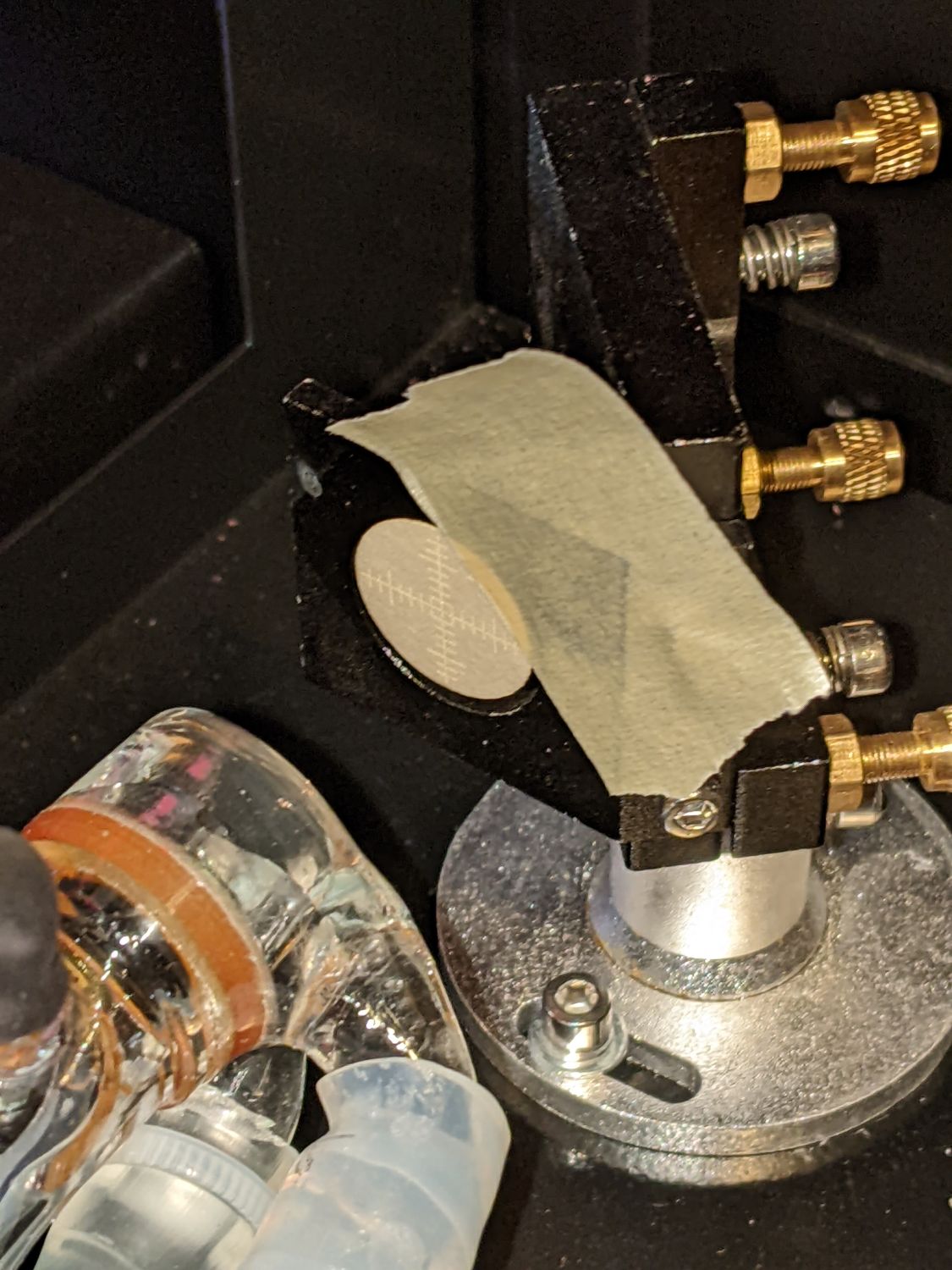
I did some very basic testing and it is obvious to me that my 3rd mirror is completely off. I’m not sure if the 1st mirror is, but it’s obvious that 2 is dead center. (Keep in mind I did do a few pulses on each).
This was quite reassuring since I’ve tried so many other possible solutions and nothing had changed.
To assess your tube status, much less power and/or time is required. Set your pulse to 20ms and adjust power until you have a light brown mark on M1.
PS. do yourself a favor and make reasonable targets and a holder would also be nice or should you stick them on a disc that fits into the hole in front of the mirrors.
It is a standard tool that is used a lot for your laser machine.
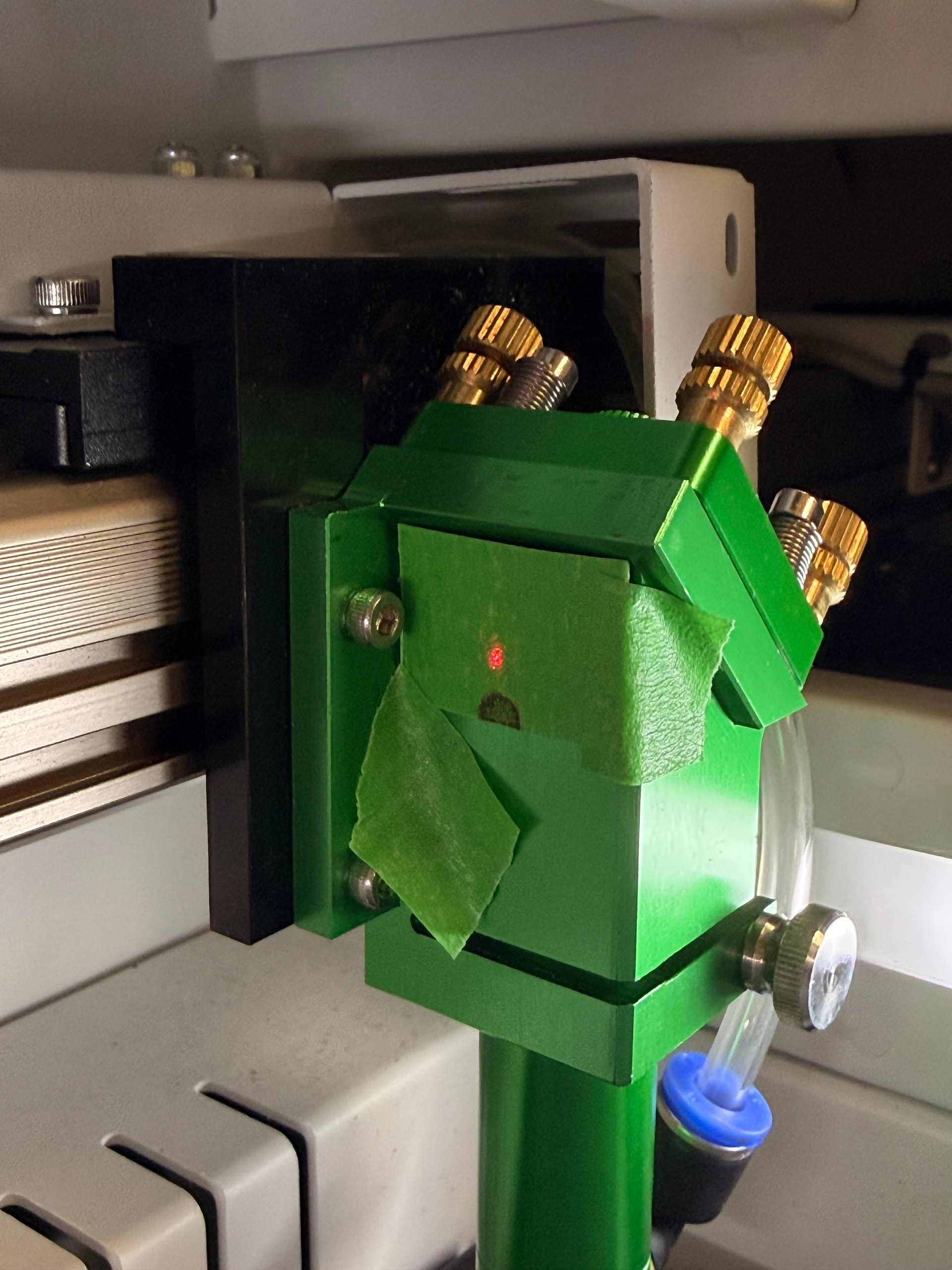
Can’t tell anything from the first mirror, the second has an odd power distribution and there is no reason the spot shouldn’t be round on mirror 3, unless it’s getting clipped somewhere in the optical path.
Depending on the power setting, TEM mode can change. My last two tubes showed TEM01 at 10% power levels. Raise the power it does come back into TEM00 mode.
I have a generic manual and a maintenance manual Ranger3 Laser - Google Drive I’m not sure if that has any use because neither ever really came in handy for me but let me know what you think
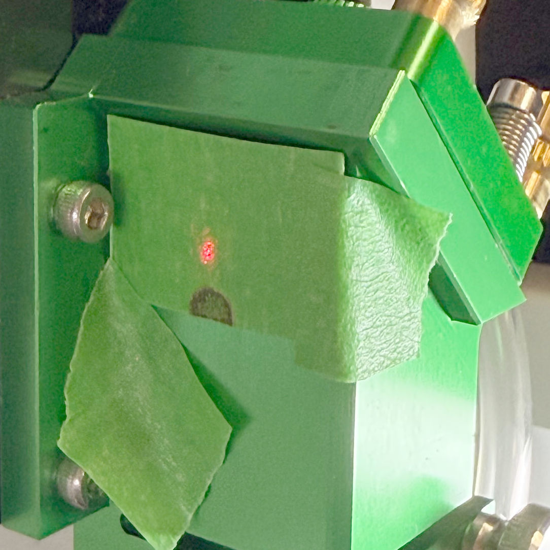
It is getting cut off. I’m assuming it has been this way since it was shipped to us. Should I be using these targets for alignment? The videos that I’ve been using he also just uses painters tape.
The scorch from the CO₂ beam should be dead centered on the red dot.
It looks very much like whoever adjusted the mirrors believed the red dot was properly aligned with the CO₂ beam, got the dot nicely centered, and didn’t notice the CO₂ beam is burning the bushes.
The manuals appear entirely generic and, in particular, make no mention of the red dot collimator.
Get on the phone with whoever sold you that thing and get the doc relevant to the red dot collimator.
While you’re waiting, you can adjust the mirrors without reference to the red dot just like everybody else does.
Assuming the complete beam strikes m3, it doesn’t need to be centered there. M3 is aligned more like catching the beam.
If you move m3 (head) up or down (Z axes) the beam in the down tube to the lens will move left and right (X axes). If you move m2 in the Y axes direction it will move the striking point of the beam along the Y axes of the down tube. The beam needs to go down the center of the tube and strike the lens squarely in the center of the lens. If it’s off one side or the other, the beam, after the lens will have the same slope.
These mirrors are not always aligned to the center of the hole, at least for the head. This was the original head from my OMTech China Blue.. note the mirror is not centered within the hole.
https://www.youtube.com/watch?v=tFbuOs_98n8 this is the tutorial I was going to follow along with. He uses a reverse alignment tool in the second half of the video, but I guess I would just follow along with the traditional alignment since the red dot collimator isn’t in line with the co2 beam
Watched part of it, I disagree about the beam dosn’t need to be centered.
If I take a 10mm diameter beam, m1 looks 20mm tall but only 14mm wide. If I take my 10mm beam out, that leaves ~4mm or ~2mm on each side of the mirror for error. Besides there should be no reason you can’t get the m1 → m2 right on. The closer these are, the better you are at m3.
The reverse tool only aligns m3 → m2, you still have to adjust m1. To me it’s like adjusting a rifles site from the target end. The other thing that goes along with these is all the adjustments are backwards… They do work, but you still have to burn some targets to check it anyway.