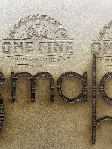
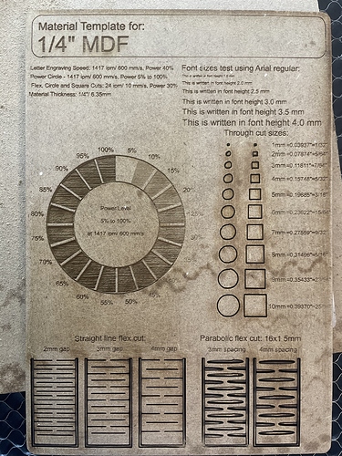
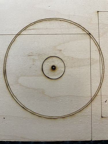
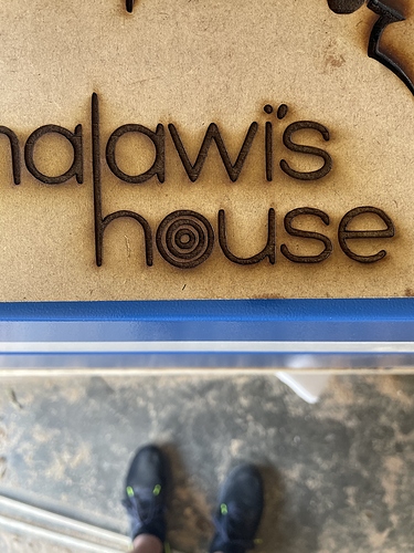
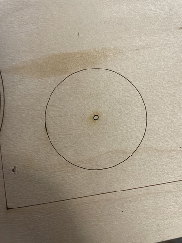
I just got my 100W eBay laser in a couple weeks ago and I’ve been trying to get everything dialed in and I’m pretty close except when making circles or really anything that requires the laser to move on both axes at the same time. The smaller the circle the more of an issue it has. I’ve tightened all my belts, I tightened the head of the laser (that was loose for some reason), I’ve squared the gantry, I’ve adjusted the curve tolerance (based off another post in the forum), and I’ve adjusted the steps. I’ve attached pictures of everything. The last picture with the two circles is my current situation and is definitely an improvement. The first picture with the writing is a fill and line and if you zoom in a little you can see that the line part is off from the fill. The second one is after some adjustments, it’s definitely better but the curves still aren’t smooth. At this point I’m at a loss and hopefully someone has some answers.
From my experience with CNC routers, it’s usually loose belts or your steps per xx are off causing the problem but since you tightened the belts and adjusted your steps, I am confused too.
When you draw a box in LB, does the output from the laser match the dimensions?
Are all of your graphics created in LB or are they a “trace to vector” or similar? Obviously an original vector graphic from within LB is going to be much more accurate then a scan or trace. Just a thought.
I’ll second the calibration question. You want to do as large a rectangle as you can for calibration. I’ll also warn about over tightening your belts. You can start to see some ‘jittery’ lines if the belts are too tight and the pattern of the teeth start transferring.
My boxes are spot on after adjusting the steps. The logo was a trace but my preview image is completely smooth on the curves. All my boxes and circles were made in Lightburn.
I can mess with the belts some more but I only have an issue when both axes move at the same time. If it’s just running one axis the line is smooth and accurate.
I can’t give any more hints. My WAG might be a step imbalance in your stepper drivers, but that is a true WAG.
Check and make sure the mirrors and lens are not loose. This means check the mirror mount to frame as well as the ring that tightens against the mirrors and lens. I had one mirror loose a while back, did weird things.
I’ll definitely give it a look in the morning and let you know if anything changes.
Acceleration and speed in small circles & curves, is too high.
It can’t recover well enough after trying too hard to speed up, so it overshoots and makes egg shapes, before recovering back to the starting point.
It’s not loose belts, etc, but software settings edits are needed.
I would love to know where that material template came from, I would love a copy of that.
I’ll chime in on the template. Hopefully a dxf file so it can be easily shared.
I just found it on thingiverse and made the adjustments I wanted.
I’ll post what I have a little later.
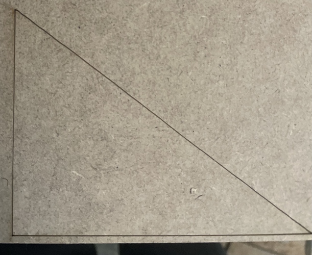
I forgot to post this picture but there’s even some wobble on the hypotenuse of this triangle. Also I was only going 10 mm/s (it was supposed to be a cut through) on the test card, I’ve definitely gone faster when I was still using my jtech on my cnc without issue. Could it be because the gantry isn’t as rigid?
The weird part is that you are only getting the problem when operating box axis at the same time. I still want to fall back on my WAG. Wrong steps, too course of steps, a mismatch in steps. If it was a loose item you would see it predominantly in one axis or the other depending on the problem.
Only other thing I cold throw into the mix is if you are doing this at the low end of your power curve in the pre-ionization zone. You can get some interesting effects from that. If you get it all across the power curve you can eliminate the pre-ionization thought.
At this point I’m willing to try anything so I’ll up the power and see if it has any affect.
The acceleration factor is the most critical figure- in my opinion- moreso than speed, although both are involved.
Not sure what machine you’re using, but any recommendations on what would be best?
I went to thingverse.com and searched and here you go. it was a cdr file and I converted to svg
original cdr file
https://drive.google.com/file/d/1B-VFM-lYKLjYZ1WtQVzdGXVf7jXF3wjI/view?usp=sharing
converted to svg file
https://drive.google.com/file/d/1fOwHUkidQXb_O-8fRZBfOJbuqdr_v88i/view?usp=sharing
edit:
would someone more experienced than me explain how the “engraving test” circle will work.
I am guessing I need to export this as a image and then engrave it with jarvis or grey scale. I was thinking I could use the Power scale in shape properties but I think that applies only to separate shapes.
One other thing to check is a loose lens in the head. I had that once and it took a while to figure out the uneven cuts. If it is loose, then moving in more than one axis is likely to cause it to wobble.
