Wrapping sheeting around a curved 3 dimensional object

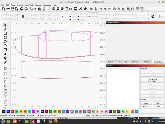
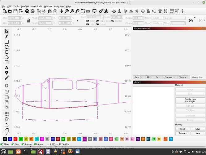
I’m redesigning an old school RC plane and it’s calling for sheeting to be placed in certain areas. This is basically wrapping a flat piece of stock around a curved area, and it also has it’s own taper to the width as well. If you look to the top section of the fuselage, that’s the shape it’s going to be width wise, and the side version shows how it’s going to curve, or wrap around it. If I draw it simply flat, as in only using the top view, it will be too short since the curve or bend will be longer then a flat, straight piece of stock.

If I convert the curve to a straight line, it’s beginning and end points remain the same, not extending when flattened out like a real world piece of stock would do. I wish I could get rid of the anchor points on the ends of the curve and still have it be able to convert to a line, now one that’s longer which when put into the model, will be the exact length needed.

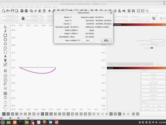
Using the measuring tool doesn’t really help at all, it will not measure the length of the curve area it’s fitting in, not the actual length of the line itself. Showing the curve and a straight line, and it’s measuring both as being the same, but once that curve is cut out, the curve will be longer.


I have both the lower and the upper part/top/bottom to cover with these compound curves and I can technically build the plane without them, then manually cut up stock to fit, then measure and/or scan it to use as a template to have the laser cutter produce a duplicate part that will fit, but surely there has to be a way of not having to take this manual approach, for this is going to be a common thing I’ll run into as I develop more planes like these.

Showing another view to give an idea as to the sheeting underneath it will need to wrap around.

mini-mamba-1

Thanks in advance for any help or tips along how I should be going about this. Surely LightBurn has something in place for the work around and I’m not stuck having to still manually cut, scan and measure certain parts. This is a very simple plane, they get much more complex then this so I’d rather have something better to work with.
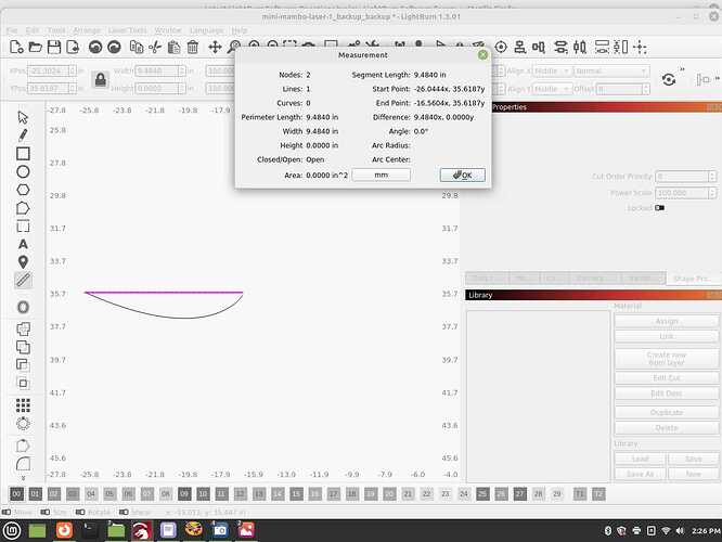
I’m not sure if I’m understanding the complication with the measurement tool. It seems to me that either the segment length or perimeter length (in this case since these look like unclosed shapes) give you the length of the curve.

Do you need something more than that?

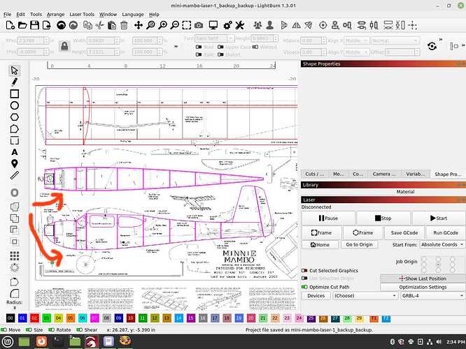
If you look at the top image, with the top arrow, you see how that flat sheet is tapered on it’s sides? It then is curving around the sides of the fuselage. I can draw in the top view, but when I curve it around, it will no longer be aligned. If I stretch it after it’s drawn, for the true length of the stock, it will again, not line up since stretching is symmetrical, but the curve is not, it’s a steeper curve at the front section compared to the aft.

I guess I’m still not understanding the complication in terms of what’s missing.

The measurement tool does seem to be able to get you the actual curved length if you wanted to attempt to account for the difference in length due to the curve.

Also, do the plans not already account for this knowing that a flat piece will need to be curved when assembled?

I did a work around sort of, by getting the length of the curve, end to end, in a linear manner, as in the length of the stock when flattened out figured out by stretching the top view version. It’s not the best route since it slightly makes it a little narrower, probably fine for this model, but still it would be better to have another way that’s more precise.

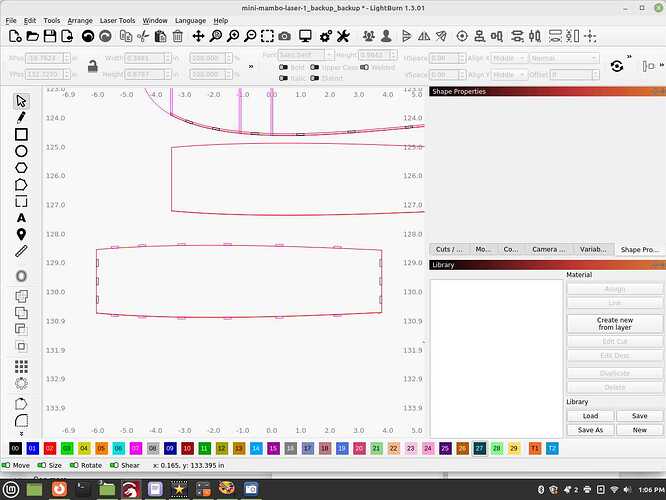
This screen shot shows the lower sheeting, as seen from above, below where it’s going to wrap around on the bottom of the fuse. Not entirely being in the clear since I am wanting to add tabs so the lower sheeting locks into place with the side, getting the tabs to line up is not a matter of simply copying and pasting the tabs on the side sheeting, pressing the down arrow so they are lined up, for they will be spread apart slightly. Take note with the screen shot showing the lower sheeting is longer then the side sheeting in that one area due to the curve.

1 Like

As someone interested in building some model planes, thank you for starting this discussion. I’m going to take a peek later at a design and see if I can fully comprehend where we could improve the tools we offer (potentially) for this sort of work! We’d be really eager to see your results in #finished-creations !

I was also interested in this. I looked up a few plans/planes, and from what I could tell, many of them seem to be just scam sites. Not sure, but hey…

So I would like to see more on this. It’d be really cool to burn out a couple sheets of wood and help my great grandson build something.

I do have the first plane I developed and have it as a laser cut kit which I’ve sold around 8 of, details are at happyrcflyer.com, I call it the Jenny Stick. It’s an amazing flyer and pretty easy to build, even for the new builder. It’s using a simple, stick based fuselage though. I also have a scale format, biplane Curtis Jenny most of the way done, the fuselage is also the more difficult part to contend with, so hoping to pick up some tidbits of insight going with this simpler plane, called the Mini Mambo. A scratch built version is at the top of that web site as well.

People were drafting in two dimensions for ages, certainly this is just a computer version of that same format, this should be doable in it, just figuring out how is the hard part. I haven’t given up, but I may end up busting out pieces like this lower sheeting by hand, then measure, scan, etc., back in to use for the laser cutter, just so I can move forward for now.

I actually ended up buying an older RC hobbiest’s pile of balsa sheets and rods + wing coverings, so I have all the materials on hand to build something like this. When I have some time to spare I’ll probably buy one of your plan sets to get started - thanks for the link :slight_smile: nice looking designs!

I’ll help you out on the files when you opt to get into making one of these, not sure what kind of a charge I would be going with, will just give you a copy as long as you just use them for personal use. I’ve had people ask for free copies of the files but they had absolutely nothing they’ve done themselves to trade with, likely they were just fishing to use them to sell.

I may in theory have found the work around for this dilemma, at least for a, it’s enough for now and should n theory line up. I shrank the sheet back down to the length it was originally from just the top view. I then pulled the tabs that were on the side sheeting or side profile of the lower sheeting, brought them over to the now shrank down lower sheet, lined up around the edges and expanded it as a lot together back to the correct size. I was expecting to have to use the now, what are supposed to be slightly longer tabs as just the spot to bring in the original tabs, and use what is in the expanded view to center them on, but the tabs never registered as a different number value so just left them in place.

You should notice that the tabs when they are placed on the parameter of the sheet, are not at a right angle since they are following the curve which adds further complexity to this task. There is no way I can know for sure if this going to work until the parts are cut and I start assembling but it should at least be very close so I can fine tune it afterwards.

Wish me luck, this should get a better visual.


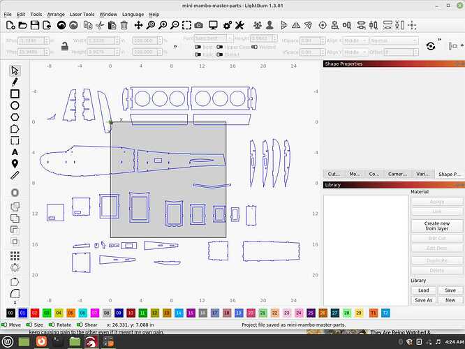
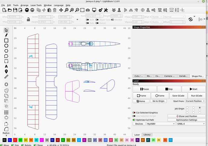
I’m finally ready to commit this to the laser cutter. Showing the individual parts that I’ll be assembling the cuts from. This is my second project on the laser cutter, in theory no revisions will be necessary but I just can’t know for sure until it’s committed to real world, solid stock and onto the assembly.

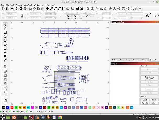
Upon creating the plans that will need to be printed to help assemble the plane, it is a good idea to fit the components still in digital form together to make sure they line up. Needless to say, I still had to do a ton of revisions.

What has me perplexed, I’ll draw the component, making it absolutely perfect, exact, then review a few days later and it’s off, like it’s shifted, or no longer square. It’s not noticeable until you zoom in to the maximum level. I’ll adjust, fix, and come back and again, it’s off in some other area. These parts should have lined up perfectly but when I got to this stage, they did not. Is this drifting thing some weird glitch in the software? I’ve worked in other software where I’ve pushed it to it’s limits and it starts acting funny, it was more of an issue when I was a Windows users, heck I killed computers by overworking them lol.

Anyway, in theory this is just it, now time to turn them into cut sheets for the laser cutter, the ribs will need to be duplicated for that element.

A feature I wish this software had was converting a group to a symbol or object, this way you could make copies of it and revising just one of them will adjust all of the duplicate parts. It’s something used in Flash, an old school graphics/animation software that shares very many of the same things as this, to the point I almost think it’s source code could be combined with LightBurns for greater functionality.

1 Like

Really interested in this project! I have a lot of experience in flat pattern making for clothing production, which might be helpful here, seems like some very analogous problems! If the method you’ve tried doesn’t yield the results you’re after, I might have some further ideas! Just commenting here so I’ll get notified. Out of curiosity, what material are you using to do the wrapping? Does it have some malleability/elasticity when formed (e.g. fiberglass+ resin)? Or is it something without any ‘give’ like cardstock or a sheet of plastic?

With regard to the shifting, it’s easy to accidentally resize something while clicking around, and I wonder if perhaps this is what has happened, maybe? There are a few ways to avoid this; you can lock shapes. You can also lock the sizes of everything in the whole document using the toggles at the bottom of the workspace:

We also do have the ‘symbol’ feature you describe, we call it a Virtual Array. :slight_smile:

1 Like

I’ll look into the tips for those options, I didn’t see it had it, still learning the software obviously.

It’s 1/16 balsa which can bend based upon how you have the grain pattern. In the curved areas that have to wrap around the main fuselage, I’ll be having the grain going sideways. Being that it’s not paper thin, the thickness does throw things off as well.

I thought personal error as well with the shifting, it’s not resizing so much as if you make a perfect square for example, then come back to it and make another perfect square to place next to it, it’s no longer on the same axis or plane or square as the original. It’s very minor, you have to zoom in to maximum level, but with the nature of these planes, you can’t have it be as sloppy as that, at least that’s not what you are supposed to do even though the kit manufacturers can and do get very sloppy about it. Mine have to be exacting on all levels if I’m to be taken seriously, more so, the builders of these give positive ratings and endorsements which in turn helps my hobby for now, soon to be a real side business cutting out and supplying kits to the masses in this hobby.

Do you have any screenshots of the off-kilter lines?
I would still recommend locking the scale or rotation for your document to try and prevent this from occurring.

If it helps during your fixing process, when node editing, you can hover over a line and press ‘A’ to align the object to the closest axis (horizontal, vertical, or diagonal) based on that line.

The alignment tools may be of use to you in aligning parts as well:

1 Like

Excellent tips shared! Thank you!

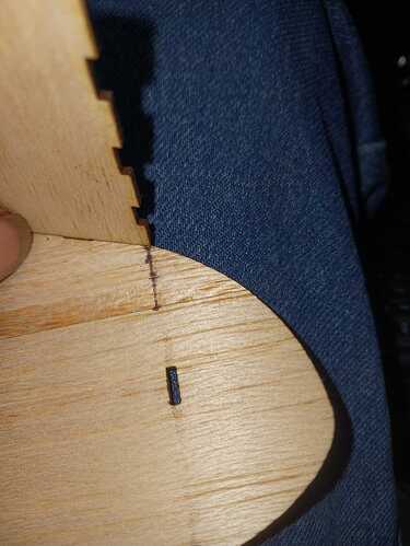
I finally was able to cut up the stock and the front section was about 1/16" short. I extended the length and cut out a new one which seems to fit in perfectly. I’ll go back over the master sheet to see where I went wrong, if I did anything wrong. I did the math perfectly I thought. I’d still would like to create some kind of template to use for these things, I wish I could click on an curve and it was able to straighten it out without shrinking it in length, it would make these tasks much easier.

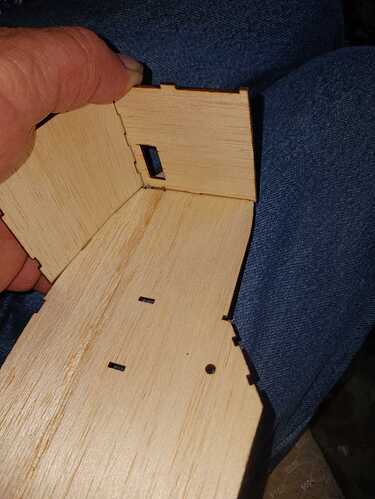
I’m showing a photo of the original, too short piece along with the recreated one that fits into place.


Finally onto proving the concept and seeing what finally is resolved. The second/aft sheeting was 1/16" too long, so I cut it back by hand and sanded to make look all perfect like in the photo. Some of the tabs were not aligned right as well, so will be revising the source files for that for the next cut run, and will be revising the cuts for this one for additional panels that simply did not translate into the real world from computer one.

Its spot on well enough on the arc elements, and as you can see, this sheeting really does lock in and square everything up so it’s rather a central part of the construction.


2 Likes


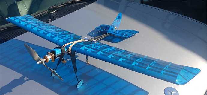
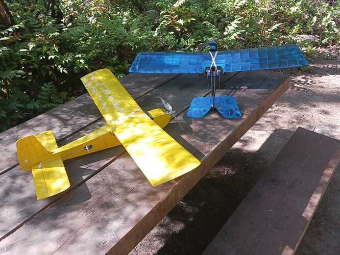
Sharing the final result, but still not exactly happy I had to make revisions to the tabs and length of the sheeting by taking manual measurements on the stock for one of them and recut, another I just revised and updated the files.

I’m moving onto a more advanced model, one that’s requiring more curves so I am back at it, trying to figure this out.

1 Like

The results look amazing all painted up!!! Awesome work!!

A potential way you might be able to minimise the revisions is to turn those curves into a series of straight lines, then you would be able to use them as references for the perimeters of other parts.

Once you had finalised the design, you could join the lines back up and smooth the connections between them.