Hello! I have had my Red and Black Omtech 60W for a little less than a year now. I am now having an issue where the x or y axis is not working (left, right, front,back). The axis that raises and lowers the bed works. Just not the x or y axis. I doubt both the x and y axis driver motors both went out at the same time, so should I check the power supply since neither the x or y axis is getting power? I have tried restarting the computer and machine. I have not found any loose or unset wires.
The laser still fires. I was in the middle of an engraving project when they both gave out. I guess my question is, if the laser still fires, does that mean the power supply is working and i need to replace the drivers? I am by no means even close to an electrician and have trouble with terms that a lot of these responses on the forums use.
There are (at least) two power supplies in the electronics bay on the side of the machine:
- High voltage laser supply
- 24 V motor supply (may also include 5 V)
The symptoms point to the 24 V motor power supply giving out, but that should also kill the vertical motor, so it’s not clear what’s going on.
When the lasers work, they’re pretty much a closed box. When they fail, you get an education … and the first step is learning the vocabulary.
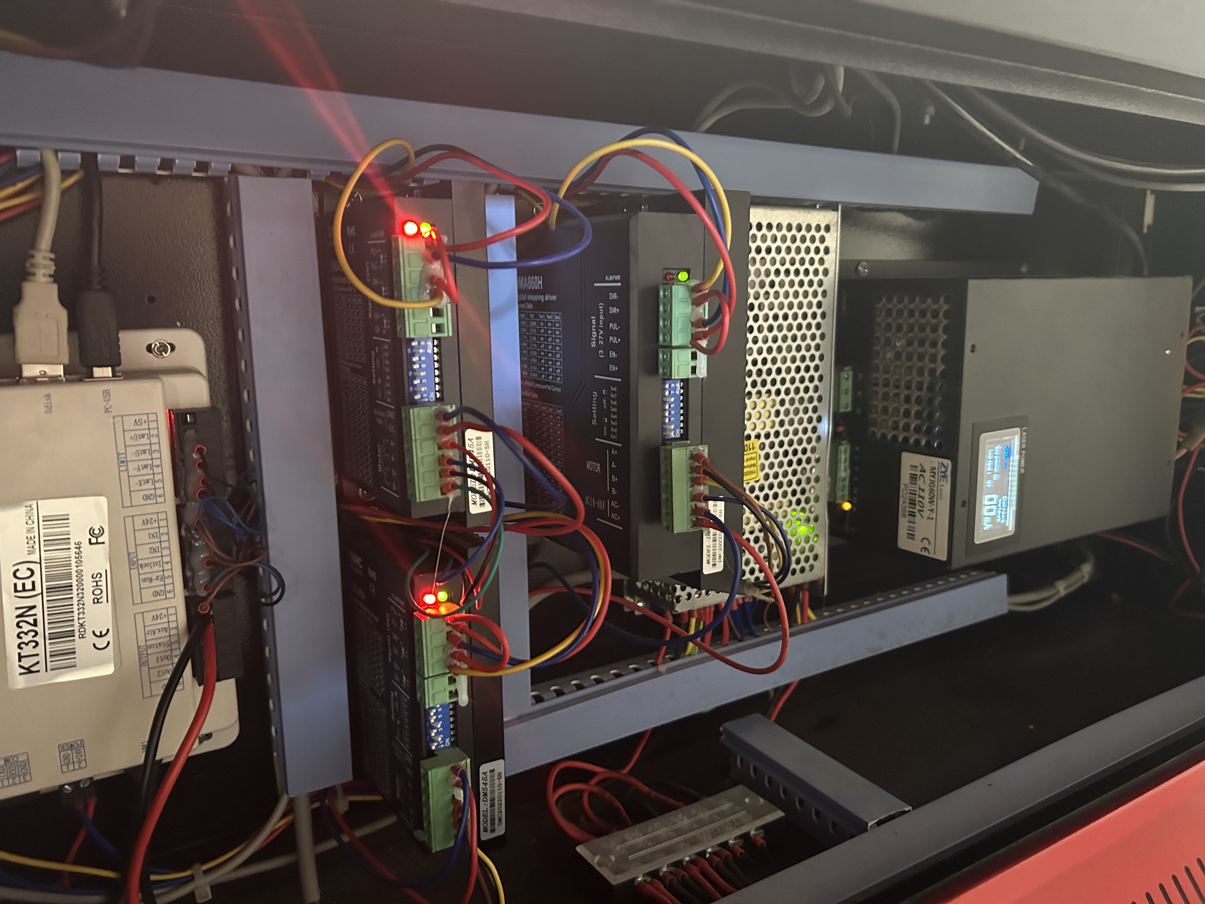
Take a look inside the electronics bay, which is over on the right on my laser, and find the stepper motor drivers:
If you find two similar bricks, they’re for the X and Y motors.
If you find three similar bricks, one will be for the vertical motor. Some CO₂ lasers have a motorized lift that does not use a stepper and doesn’t have a driver brick.
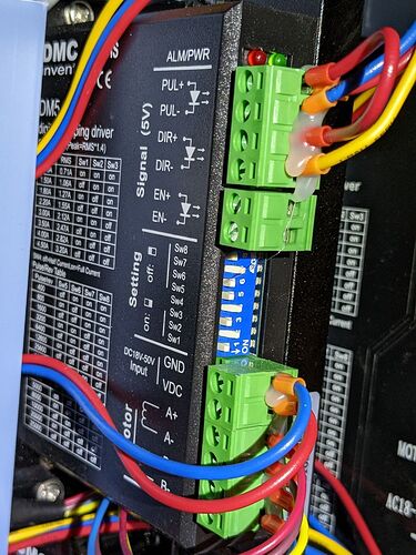
Above the upper green connectors are two LEDs:
- Red = error condition
- Green = power good
If the green LED is lit on the X and Y drivers, then the power supply is (probably) good and something interesting is going on.
If a red LED is lit, then it’s definitely interesting. ![]()
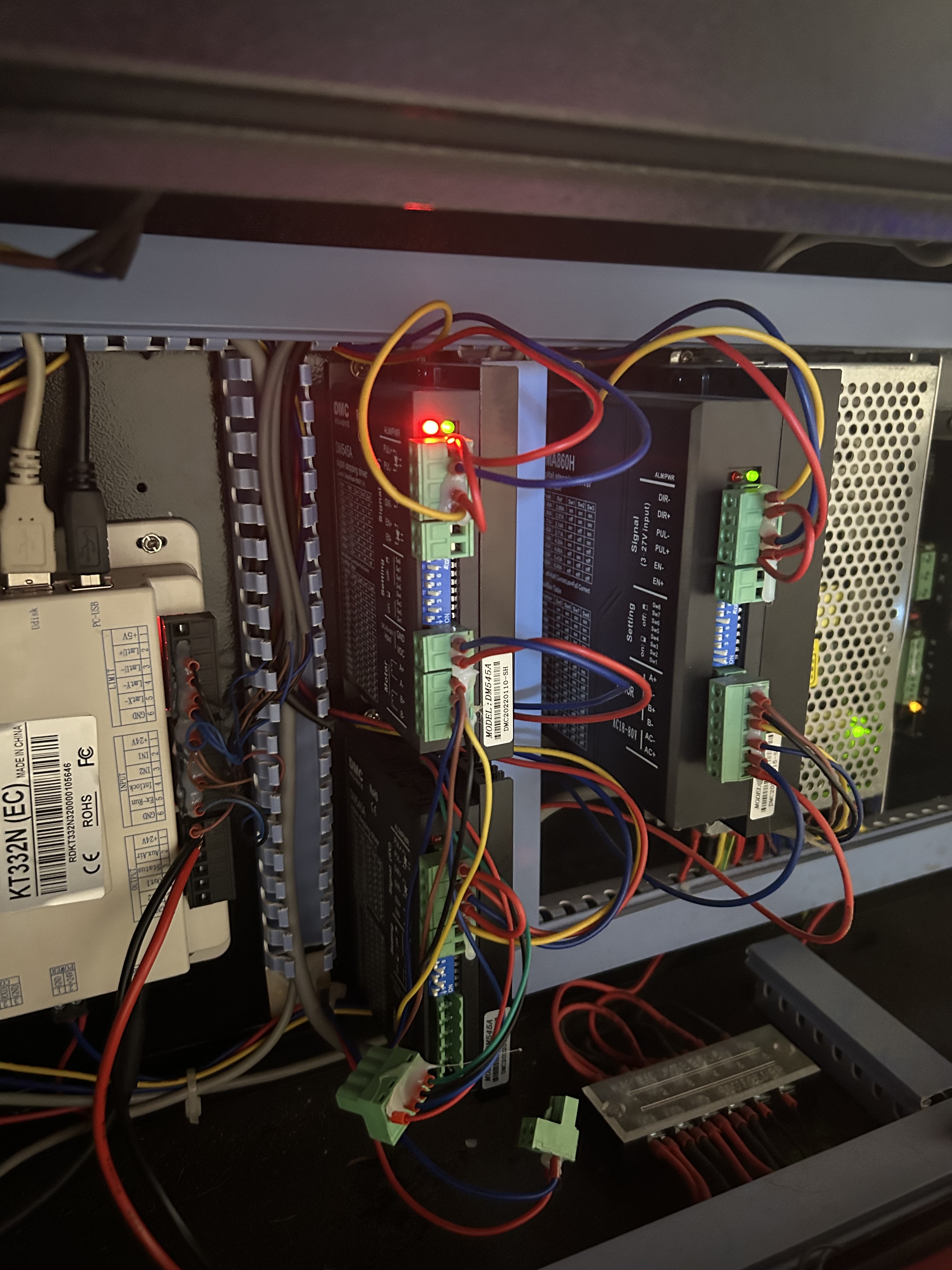
The high-voltage power supply for the laser will be a large black box like the one on the far right:
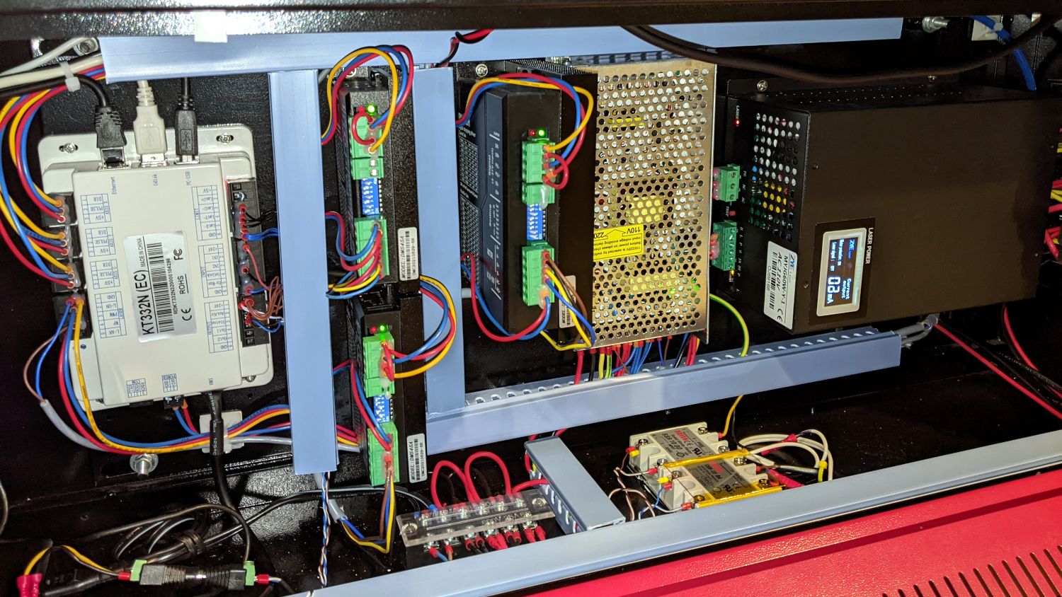
The 24 V power supply is the perforated box just to the left of the HV supply. In my laser, it also supplies 5 V for things like the red-dot laser pointer and LED lighting.
The three stepper drivers are the vertical black boxes with green connectors.
The Ruida controller is the beige box on the far left.
So, let us know what you find in there:
- Two or three stepper drivers?
- Stepper driver LEDs lit or not?
Photos are always good, but pay attention to framing & focus & lighting so we don’t develop unsightly squint furrows. ![]()
Woo-hoo! ![]()
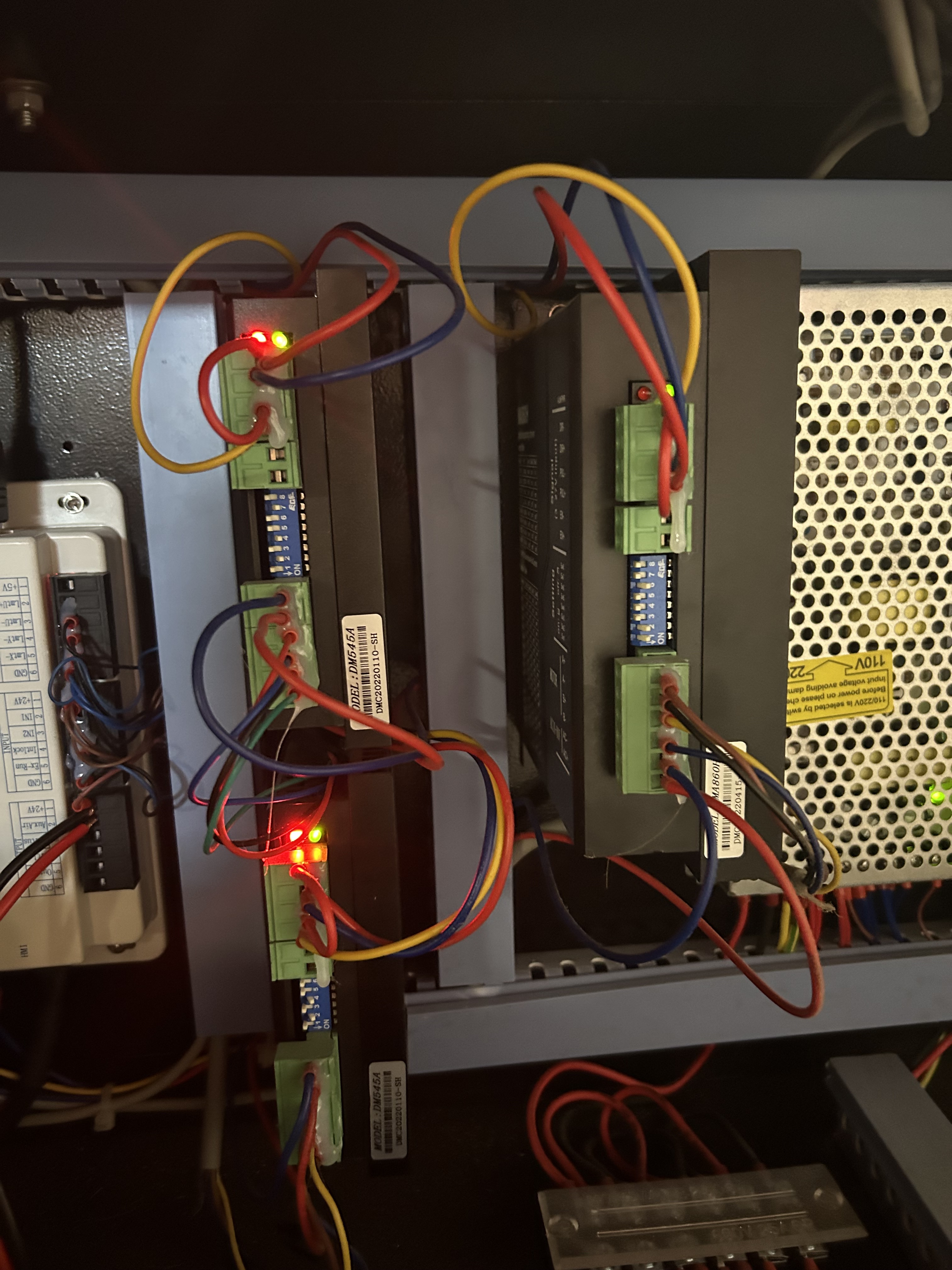
So the drivers are getting enough power to light up, but something is definitely wrong.
The third stepper driver in your picture, the big brick to the right of the X & Y drivers, the one running the vertical drive, has its red LED off.
One manual for the DM542A stepper drivers in my laser states:
- , the status on light’s indication
PWR: green, normal work light.
ALM: red, failure light, the motor with phase short-circuit, overvoltage and under-voltage protection.
A much more complete manual suggests the red LED will blink a code at you:
3) Status indication
The green LED is the power indicator. When the driver is powered on, the LED is always on; when the driver is powered off, the LED is off.
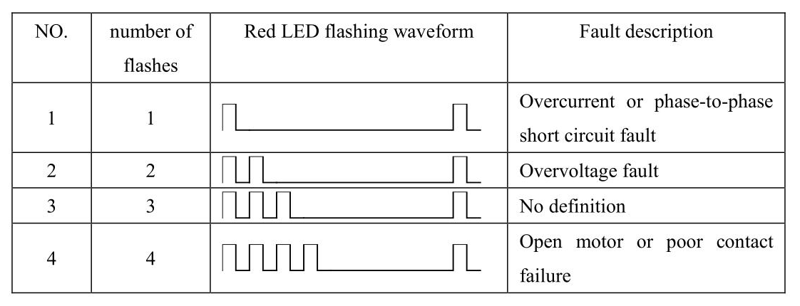
The red LED is a fault indicator. When a fault occurs, the indicator flashes in a cycle of 3 seconds. When the fault is cleared by the user, the red LED is always off. The number of flashes of the red LED in 3 seconds represents different fault information, as shown in the following table:
You didn’t mention the red LED was blinking. If it’s not blinking now, try turning the laser’s power off and back on while watching the stepper drivers to see if that encourages blinkiness. It probably won’t, but it’s worth trying.
The symptom of the failure is both X and Y stopped working at the same time in mid-operation, but the vertical axis still works.
I agree the 24 V power supply has failed, perhaps not completely, but enough to discourage the drivers. Testing the power supply will require enriching your vocabulary and possibly stocking up on a few tools.
![]()
So the driver on the right flashed red once upon start up and then stopped. The left two lit up and stayed. I have a video but unfortunately can’t upload it here.
With that being said, how would I go about testing the power supply? I mean it’s on, fans going inside, and the laser will still fire.
All three stepper drivers in my laser flash their red LED once when the power goes on, which is either a confidence builder (“I’m the red LED. Behold: I work!”) or, more likely, a startup transient while the driver’s internal microcontroller wakes up and tastes the voltage.
That the two red LEDs in the X & Y drivers stay on, without blinking a diagnostic code, is a Bad Sign™. I’m willing to believe the drivers do not have the same firmware as described in the manuals, because the market for seemingly identical drivers is saturated with clones / knockoffs / counterfeits / junk with absolutely no way to distinguish any of them, so it may just be the drivers in your laser light the red LED for any error condition, regardless of what any manuals might suggest.
That’s because it uses an entirely different power supply from the steppers, so the laser and the motors are pretty much independent. The typical failure is the opposite of yours: the HV supply goes toes up, so the machinery continues to move with no laser output.
What’s the model number on the controller in the far left of your laser’s electronics bay? It’ll be something like RDC6445 or KT332N or thereabouts. Knowing that will let us know what it has in the way of diagnostic LEDs or other outputs.
Again, a picture will be helpful.
Keeping in mind your description “by no means even close to an electrician”, now would be an ideal time to spin up any nearby geek-like acquaintances you know.
That’s broken as designed: you must upload the file to a site specialized for video (Youtube, Google Drive, et. al.) and include a link to the file here. The maximum file size is painfully small, too.
There are also arbitrary restrictions on file extensions, which you can work around by renaming the file when you upload it.
@emileybeck explanation, to me, seems to indicate that the 24V supply is alive or there wouldn’t be any operational Ruida console… such as moving the Z axes, which appears to have a stepper/motor driver…
Mine uses the same 24V supply as the steppers… I also notice the motor driver for Z has a green light… supporting that the 24V must be viable.
My OMTech had it’s stepper motor drivers set to twice the recommended current, resulting in motors you could fry an egg on… The Z axes operation may support a theory that the other two steppers were just driven too hard… The Z axes doesn’t move at all compared to the x and y axes…
Unplug the failed motor drivers power inputs connectors and check your voltage supply.
Check the current limits on the drivers… you can also unplug the steppers and see if the symptoms with the red led changes.
If the Ruida is awake, it’s getting 24V…
@emileybeck – What motor driver is in your machine?
![]()
It is a KT332N!!!
Uploading: IMG_1071.jpeg…
Not to sound like a complete idiot here, but how do I do that? ![]() and how do I know what motor driver I have? I’m so sorry for my ignorance on this
and how do I know what motor driver I have? I’m so sorry for my ignorance on this
You have to be patient for a photo upload… wait until it completes before moving on…
It didn’t make it…
This is a DM556…
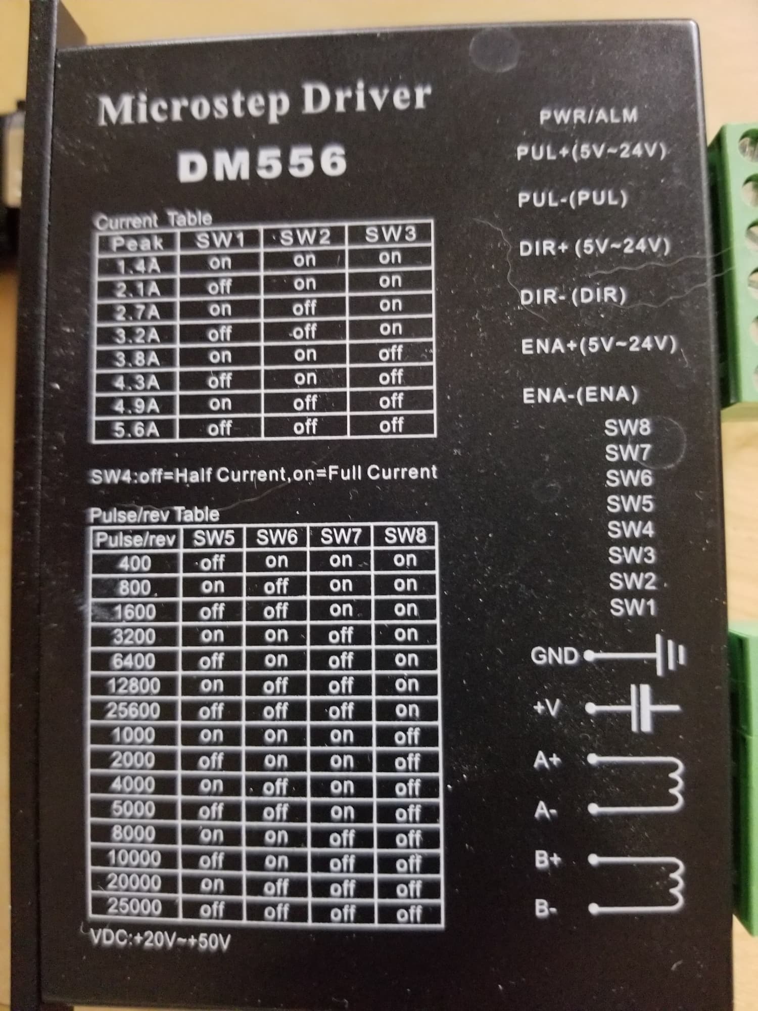
The switches determine the current limit… SW1 through SW3… which are on the circuit board, but accessible where the connectors are located.
Notice down is ON…
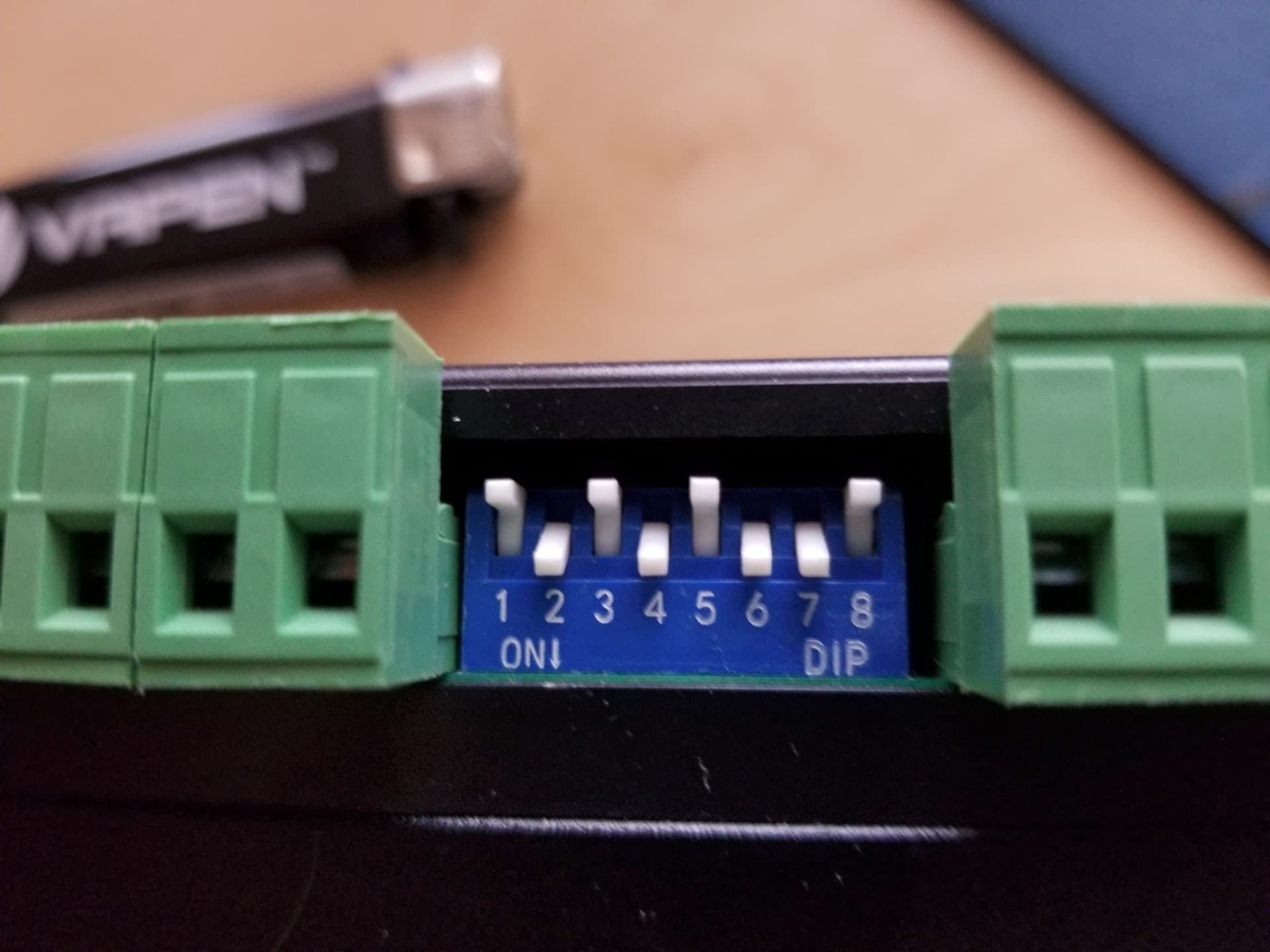
Make sense?
This covers NEMA17 and NEMA23 motors. It’s a PDF, remove the .txt extension.
Data-Sheet-Stepper-Motor-Support.pdf.txt (839.0 KB)
![]()
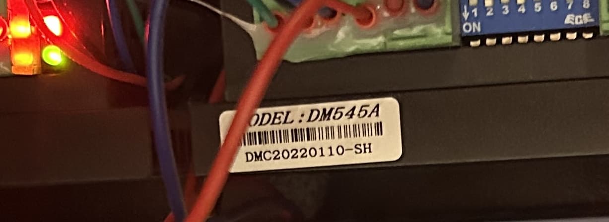
I think that’s DM545a…
![]()
@jkwilborn They are!
Im dyslexic, please ignore my mix-matching of numbers lol. I’m so sorry ![]()
@jkwilborn i unplugged them both and started up and the red nor the green light came on.
I unplugged just the top driver motor and left the bottom plugged in, and then the one that was plugged in worked and had green light on. So I did the opposite, to where the bottom was unplugged and the top was plugged in, and it had the red and green light on.
You’re very close to the heart of debugging! Well done!
Now that we know the stepper driver are DM545, some things become clearer.
The red alarm LED does not blink:
Power indicator is green. When the driver power on, the green light will always be lit. Fault indicator is red, when there is over-voltage or over-current fault, the red light will always be lit; after the driver fault is cleared, if re-power the red light will be off.
As you suspect, pulling the plugs removes the power, so nothing lights up when unplugged.
Your debugging suggests the upper stepper driver has a problem, but it may be a problem with the stepper motor rather than the driver: the driver will shut down in order to prevent damage to itself and lights the red alarm LED.
To figure out where the problem lies, let’s move the stepper motor cable from the lower driver to the upper one. We know the lower driver does not find a fault with itself or its motor, so connecting the good motor to the upper driver will show what happens.
Unplug the laser from the wall outlet, because the AC line wiring inside the electronics bay is definitely not user friendly. This is good practice whenever you’ll be elbow-deep in the electronics bay, because touching (or dropping a screwdriver across) line voltage terminals will definitely change the course of your day.
Leave the lower driver unplugged during this maneuver.
The lower four pins on the lower connector of each driver go to the stepper motor, but they’re probably hot-melt glued to the upper two pins carrying the 24 V power supply. If so, gently crack the 2-pin part away from the 4-pin part on both stepper drivers.
If they used a single 6-pin connector, you transplant the whole thing, but it’s easier to maneuver fewer wires.
Yank the blue cover off the vertical wire channel to the left of the stepper drivers, which will require strong fingers and strong words.
Un-weave the 4-pin stepper motor connector from the wiring channel until you can plug it into the upper driver, next to the 2-pin power connector.
Leave the lower driver unconnected.
Plug the line cord in, turn on the power, and see what the upper driver does. If its red alarm LED turns off, then the motor originally connected to that driver has a problem. If the red LED stays on, then the driver has a problem.
With one stepper driver missing and the axes confused, the KT332 controller will object when it cannot home the axes. Not to worry, it will be much happier with working drivers and motors.
Stay safe, work slowly, take plenty of pictures, and report back!
I guess my next question is, where can I find a DM545A driver. The only ones I see are from out of the country or are a DM452. Is there a difference between the two?
I got a number of hits for them on Amazon and Ebay, but none of them had any in stock…
If it’s a different number it’s a different controller… you’d have to check the documentation to tell if something else would be interchangeable.
![]()