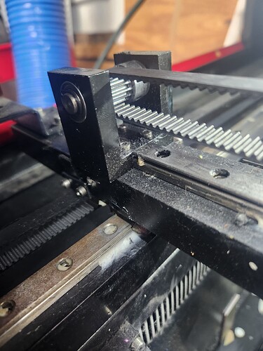
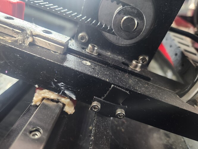
I had the laser off and I was checking on the belt that runs the laser head, I turned the laser back on and it homed, and started banging on the limit switch. I guess when I moved the drag chain out of the way it pushed the limit switch up on the x axis. I fixed that issue but on the controller when it homes it reads 1000x1000 instead of 0x0. What could be the issue?
That means the controller has not completed the homing cycle for the X and Y axes.
With all due respect: nope. ![]()
Basically, you must ensure both limit switches work correctly and are properly activated when the axes are in the home corner.
The usual switches are proximity sensors activated by ferrous metal with an internal LED up, so test them by laying a screwdriver atop the sensor target on the end:
https://www.amazon.com/PS-05N-INDUCTIVE-Proximity-Sensor-DC10-30V/dp/B0C2CGFJLW/
If they both light up, then use the controller console to display the “diagnostic” panel with the input sensors and verify the controller sees the screwdriver.
If that works, then crane your neck to discover which switch doesn’t light up when the machine homes during startup. Fix whatever prevents that from happening and the machine should be back in action.
After it sat for a while I turn it back on and was reading 0x0 at homing position.
Sounds like an intermittent problem, so checking your work on the limit switches is still a worthwhile exercise.
Also, see if the limit switches blink briefly during homing. That will give you an idea of what to look for when it doesn’t home.
Intermittent problems are the worst!
Well it hasnt done it again, and its the least of my worries. My biggest issue right now is that it all the sudden started engraving poorly and I cant figure out why. I cleaned my mirrors and they are out of alignment, but id say they have been out of alignment for a long time to be honest. I am going to attempt to align them today. Pictures are attached of the issue I am having. The one on the hat is what the design should look like.
Run this test pattern as fast as it will go, with optimizations turned off, with the power set to mark cardboard:
Any distortion in the results on the cardboard indicates a mechanical problem.
Assuming that works OK, then what you’re seeing is almost certainly due to misaligned or loose optics.
The doubled lines for small vertical strokes looks very much like the beam splashing off the inside of the nozzle and producing a pair of lines, one weaker than the other. The slight widening of the circle around the pattern agrees with that; the splashed line is covered by the thicker pattern.
If that’s not it, then you’re looking at a failed tube resonating in a mode that can’t produce a well-focused spot. Some recent discussions show the beam shape and go over the test process:
I’ll give it a go, thanks. I removed the lens tube the other day to install new red dot pointers, and it ran fine for 2 days. I cleaned the mirrors yesterday and noticed that the retaining plate was loose, so I tightened it best I could. I didn’t have the little tool you use. I am leaning more toward the tube being shot, it is going on 8 years old. I assume it’s supposed to be a fill and line layer correct? Both opened as line layers.
@ednisley I ran the test, i hope you can see the results good enough.
That’s in Fill mode, which produces nice even scans.
Run it just in `Line’ mode with optimizations turned off, so the laser head jerks back & forth over the whole pattern to shake things loose.
Aye-yup, you’ve got your work cut out for you!
But now you have a simple, unambiguous test pattern to help track your progress in finding all the loose bits.
The misshapen circles in the central pattern and the uneven spacing in the corner lines shows considerable backlash in (what looks like) the X axis drive train.
In addition to troubles in the drive train, the wobbulations in the letters suggest the focus lens is loose in the tube or the entire laser head is loose. A loose head can happen with all the screws feeling tight when the underlying threaded holes / inserts are stripped out or loose in the frame.
After you get all that sorted out, then you can start on mirror cleaning & alignment … ![]()
Yea… I think I’ll just toss this one in the trash and buy another one. Do you know of any good videos for reference to fix this issues? I am pretty sure there is a ton of slop in my x-axis belt. I can’t find any were to try and tighten it up other than where it comes together at the head. I will check the bearings as well.
That would be the triumph of hope over experience … ![]()
If you regard the laser as a parts kit that pretty much does what a laser should, then use all the adjustments as learning experiences, you’ll get this one working as well as anything else you might buy.
I’m no good with videos; other folks may have recommendations.
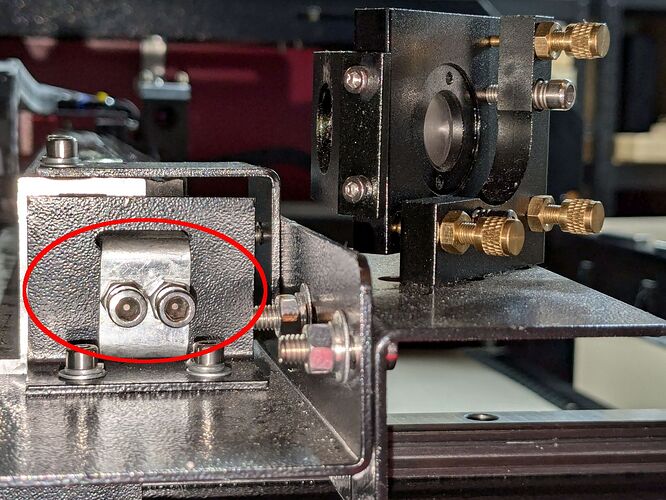
The X axis belt on my machine has a tension adjustment on the idler pulley, accessible (heck, visible) only through the hatch on the left side:
Tightening those two screws (after loosening their jam nuts) pulls the U-shaped bracket outward to tighten the belt.
There’s a similar arrangement for the two Y axis belts, although I devoutly hope I need never maneuver a ball-end hex key through the single small hole in the front panel at each idler that’s supposed to allow access to both of its screws.
I’m just frustrated right now, got orders to do and i have no clue what I’m doing. I’ll look again, but I didnt see the tensioner before. I’ll keep on keeping on, maybe I can find someone local to come give me a hand. I have a video of the belt on the x axis but I cant upload it here. Thanks for your time.
Unfortunately it would appear my don’t have a place to tighten the belt, other than where it comes together at the laser head, so I am out of luck there. I am going to measure this belt and find a replacement, maybe it has stretched over the 7 plus years of usage and that will fix the issue. The head it self is tight, other than the play drom it sitting on the rail i feel no movement. Can I email you a video of the belts?
Those belt clamps look teleported from the Iron Age!
You sure the idler pulley isn’t mounted in a sliding doodad?
If it’s not, I suppose you can grab a belt end with a Vise-Grip and haul on it while loosening & re-tightening the clamp screws, but … ick.
If you can feel any play / looseness / slop, then that’s part of the problem you’re having with that machine. The trick is finding it, which boils down to figuring out which part is loose against another part that’s not, then figuring out how to eliminate the looseness.
All of which seems to involve nuts & bolts, so don’t give up hope. Wiggle each part gently and figure out why the thing that’s supposed to be holding that part in place isn’t doing its job.
Given the age of the machine, however, the belts may be worn out and need replacement, rather than tensioning. Ditto for the mirrors & lens; if they’ve rarely been cleaned, you may as well replace them rather than scrub the polish off the poor things.
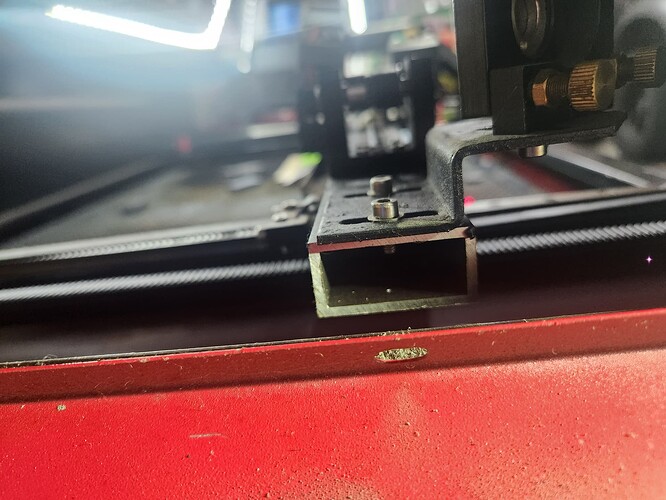
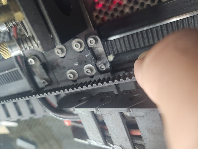
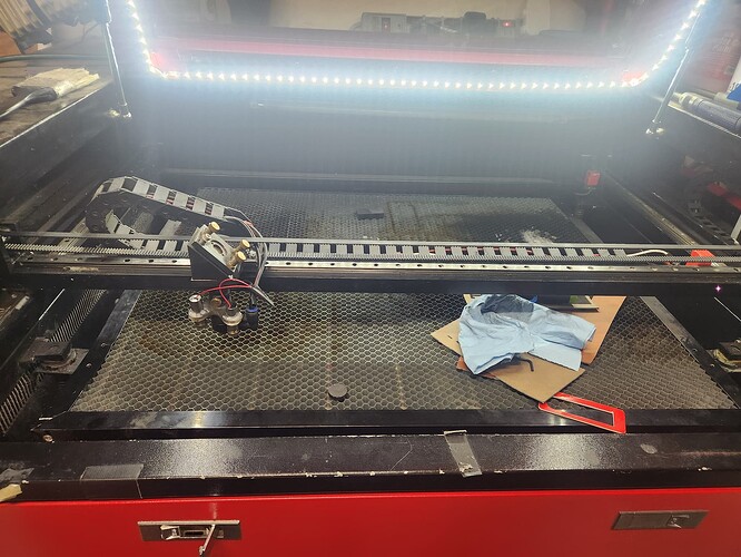
I sent you a video in a DM, yea the only way I see of tightening the belt it to pull on it, but I need another set of hands to hold the head still and tighten the bolts back down. I tried it by myself earlier and didn’t go well. When my son gets home I’ll get him to be my extra set. I’ve added pictures of both ends of my X gantry and the gantry itself. I dont see any way to tighten anything. On my Y axis belts there is a place to tighten, just not the X. I’m ordering new mirrors and belt, just got to ttake this one back off to measure. Are all mirrors the same or do I need measure those too?
The motor mount has slots for the four mounting screws with about two teeth worth of adjustment range:
- Loosen those screws
- Slide the motor toward the laser head to slacken the belt
- Snug the belt at the clamps without overdoing it
- Then shove the motor to tighten the belt
- Hold the motor while tightening the screws
I’d be tempted to use my Designated Prydriver to lever the motor against the end of the linear bearing, but that may be getting entirely too primal. ![]()
AFAICT, the only way to do that is to set it up on Youtube or something like that, then post the link in the message. The forum admins don’t want to host huge files and that’s one way to enforce it.
It’s hard to judge from here, but the Y looks fine and the X looks like tightening it by a tooth or two will get it done.
I’d go with loosening the motor, taking a tooth out at the clamp, then seeing how far the motor will slide.


