I have a project with both cutting and engraving. The cutting is 10mm/sec. I have some line engraving at 20mm/sec, but I have letter engraving at higher speeds (see below). Because the inside of the letters falls out at 20mm/sec 10% power, I’ve been trying higher speeds. Examples of inside are for letters R, A, B, 8, i.e. the part of the letter completely enclosed by the engrave line is falling out.
I’m measuring error as the X offset from the top point of an “A” to a line that should be vertically centered with it.
At 20mm/sec I have no appreciable error
When I increase speeds, I have leftward drift on the X-axis. The drift accumulates with leftward distance from the origin and is negligible close to the origin, i.e. the X offset error is not constant but increases with distance. The preview window shows letters being drawn from left to right, so the offset error also increases with the duration of the letter engrave operation.
At 25mm/sec I have a drift to the left of approximately .3mm, 14 inches left of the origin.
At 60mm/sec the drift to the left is approximately .7mm, 14 inches left of the origin.
So it seems the drift is increasing as a linear function of speed. I could run run more tests to interpolate.
I would think a loose component (belt, etc) would have eccentric drift rather than consistent X-axis drift. All cuts look good an line up (they are on different layers), so this problem seems specific to lettering BUT I have also noticed circular offset fill running at high speeds accumulating drift in the x-axis (I thought I failed to secure the workpiece properly, but maybe not). Left/right fill looks OK at 150mm/sec but maybe there is a less than .1mm offset there.
My questions are:
Is it unreasonable to run letter engraving at these speeds? The letters are 2.5mm tall and 2mm across, capital letters
Is there a software setting I should check in lightburn (Ruida controller), or should I check hardware (loose belt, etc).
Does anyone have any general advice for this situation?
First off, check to see if the Ruida is using the same active edge as the stepper drive.
If it’s mismatched, then the Ruida will change the DIR pin at the same time as commanding a step. The drive doesn’t know if it was told to step forward or backwards. It will only be one step per direction change but it builds up, and may be speed-dependent.
Otherwise, same old suspects- if the timing belt is loose, worn, or the pulley is pulled a bit skew, it can walk over the teeth. Or the pulley is slipping on the shaft.
Or, ednisley may have guessed it- might just be backlash and can be addressed with correctly calibrated scanning offset. But that’s not cumulative
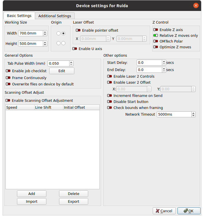
AFAICT, the Scanning Offset Adjustment corrects for the constant-ish time delay through the HV power supply that causes a linearly increasing offset with speed.
Mechanical backlash would be constant with speed, so the offset would remain the same. I think the Initial Offset value could compensate for backlash, but it’s likely to decrease linearly with speed.
No I’ll try that. FWIW the problem is occurring in a cut/line layer
Apologies I’m not sure what I’m looking for here. In the device settings I see PWM rising edge valid=TRUE for the X-axis but FALSE for Y, Z, and U axes. I assume these are the Ruida settings; could you clarify where the stepper drive settings would be located?
In a referenced post Ed suggests rising edge valid should be the same for all, so I’ll try that first.
I’ll take a look at these; they seem to be mentioned in other posts related to this topic
Are these in Machine Parameters -> Cut Parameters and Machine Parameters -> Engrave Parameters? My cut is 10mm/s and my engrave are 20mm/s (X) and 15mm/s (Y). FWIW the problem is occurring in a cut/line layer
Unless the stepper drivers have truly bizarre wiring not seen in bone-stock OMTech machines, the X axis is incorrect. Flip that switch to False, run the same pattern at the same speed on cardboard, and it should work fine.