Hello, I am fairly new to laser world and engraving in general. I setup X tool and have been trying to troubleshoot the home button grinding issue. Been going through the forums, but solutions mentioned not helping so far. Updated the coordinates and did nothing. Re-routed the wiring and that solved the X axis grinding issue but Y axis still causes grind and crashing into frame.
When I check the console window, I see that the X axis limit switch is triggering but Y axis is not.
Any help is much appreciated.
Thanks
So, you answered your question. Your Y limit switch is not being tripped. Out of adjustment, not wired correctly?
Anyway I can check that? All I did was that the pin out and reconnect it…the small yellow one. Not sure how to adjust or check for out of adjustment.
Move laser to middle, click home and manually trip your Y switch and see if it stops laser. If it does then power off laser and move laser to Y stop and see if it is tripping switch.
In Standard GRBL the report requested by typing ? into the Console window (followed by Enter) in LightBurn shows the status of the Limit switches next to the letters Pn in the output.
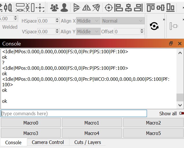
Enter the Question mark in the Console window (followed by Enter) and look at the output, hold and trigger either limit switch and repeat the question mark to confirm that the switch works as anticipated. repeat for other switches.
If the previous wiring routing pulled the limit switch wiring connector out of the controller, or if the switches were swapped then you might be ok.
Occasionally, poor crimps at the terminal block cause the wires to break in service. This can cause intermittent success and be difficult to troubleshoot.
Replacement cable assemblies are available from the manufacturer or in the aftermarket on several sites.
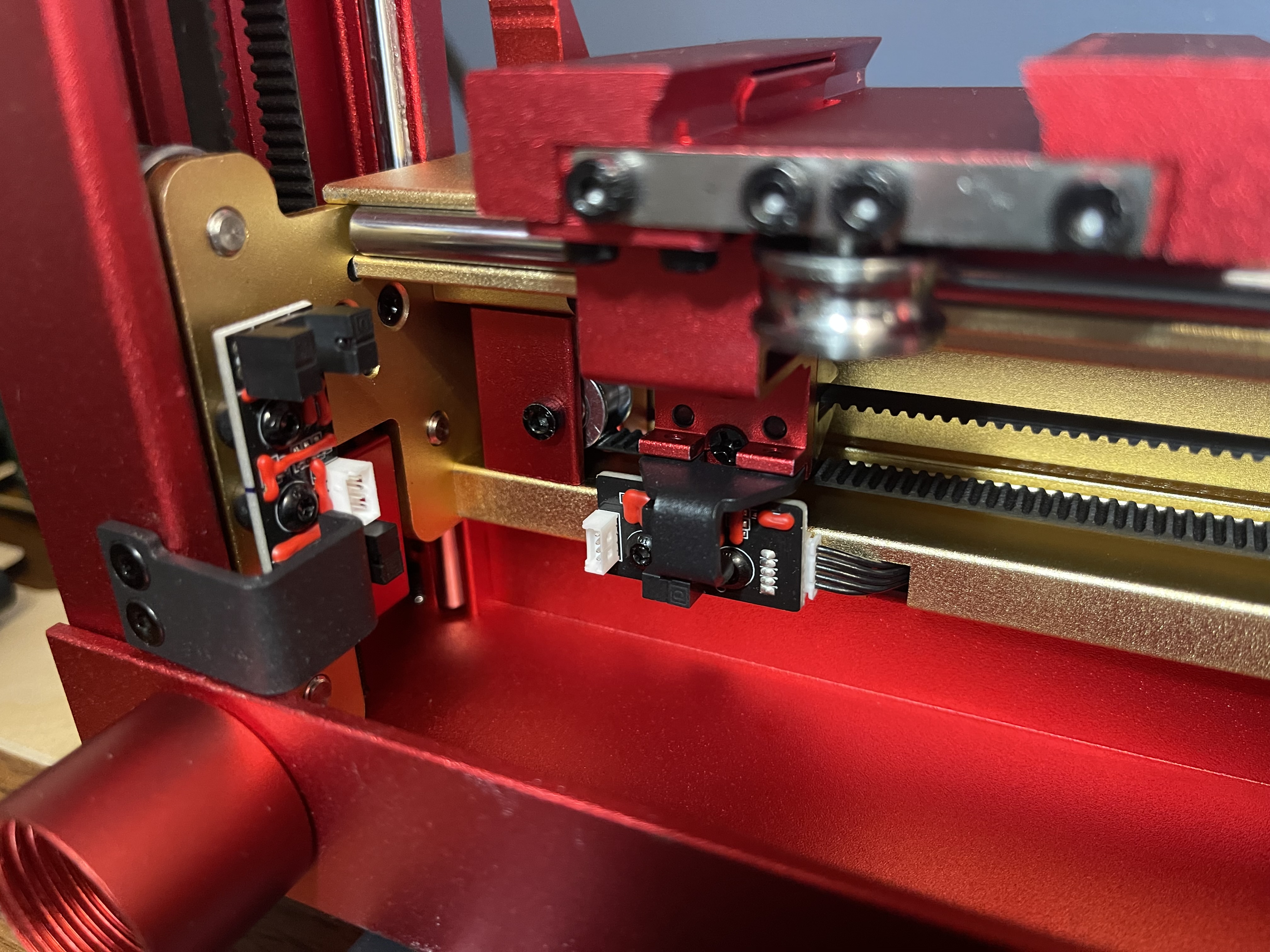
I just got the same system last week and encountered the same problem. I resolved it by moving the Y homing flag. The flag is the black metal piece in the upper left corner that is held on by 2 small screws (1.5mm hex I believe). I moved the flag towards the center (Y - direction) by removing the screws and re-mounting the flag in the new position with only 1 screw. The picture shows the “new” position of the flag. You do lose a slight amount of Y travel doing this, but it also allows more room for cables.
i tried obstructing the switch manually, is that how you suggested? I will post some pics below so I understand which is which…
Not sure I understand the orientation, sorry
I have the base upright and the position is far back (diagonally opposite the on/off switch).
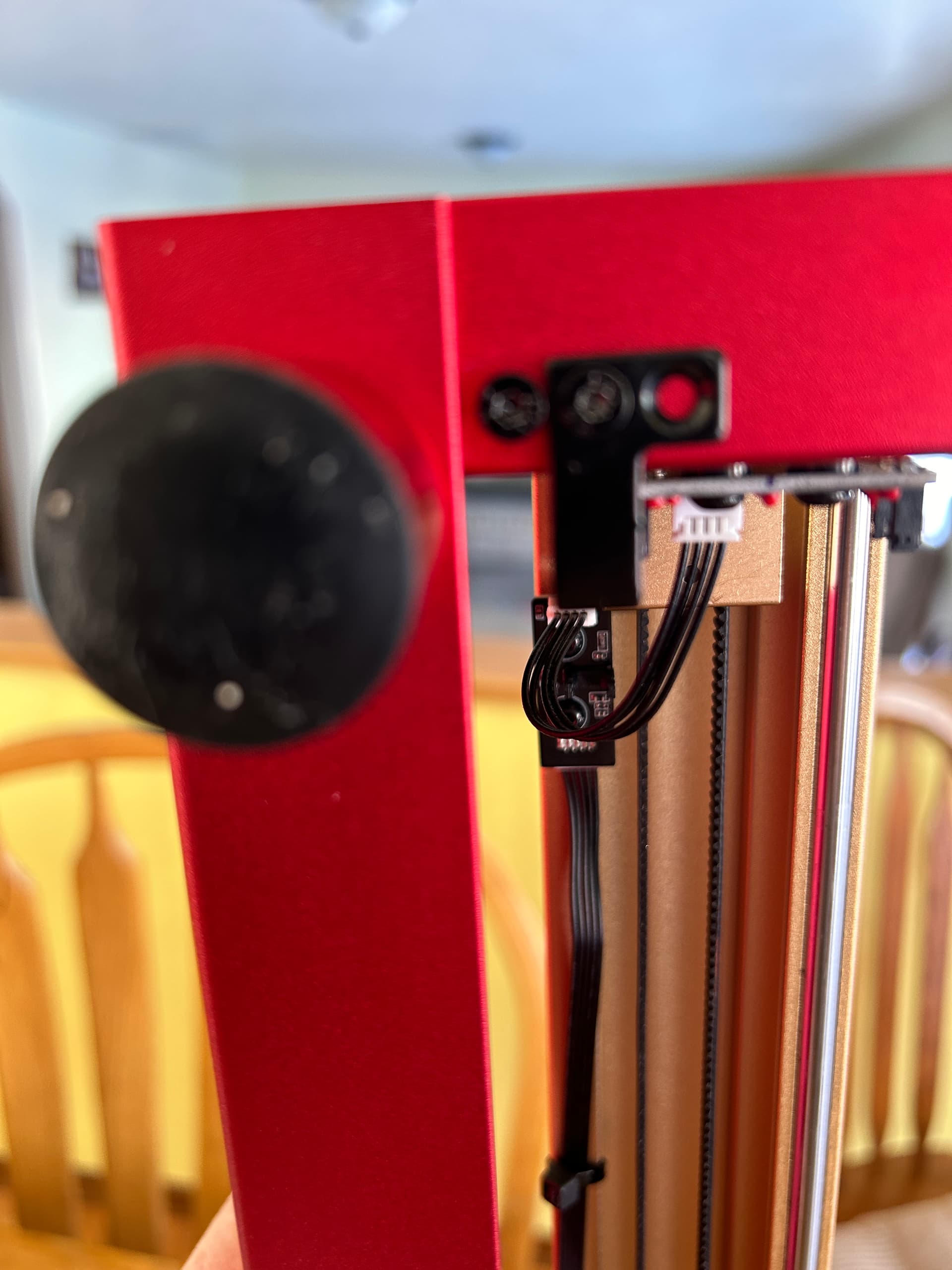
I notice 2 limit switches on each end of the yellow cross slide which are positioned on the bottom and one on the side that is near the roller. The one on the side does not have any wire connecting this switch…might be a stupid question but is that common? Am I missing something in setup?
I also notice your flag “black piece with 2 screws” is a different design than mine. No need for you to move yours, as I had to do.
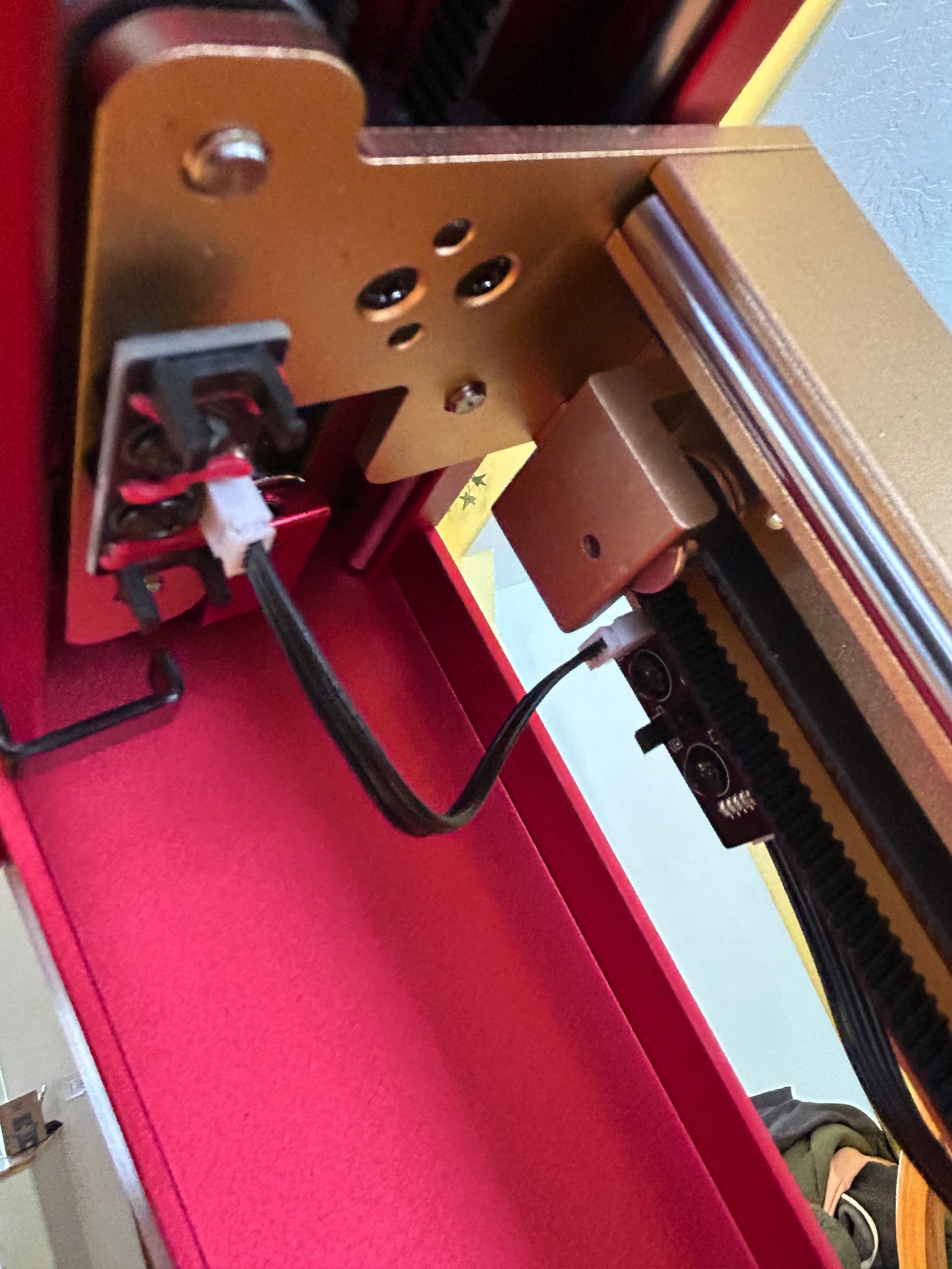
Whoa…yes it did work. Found that jumper cable in the X-tool box. I ignored it at first during setup as it said something about needing 2 pin port for 40W laser only. I added the jumper and it homes perfectly. After scratching my head for over a week…glad it was that simple
1 Like
Thank you kind people for taking time out of your day to help completely unknown stranger. Really appreciate all the input.
Thank you
1 Like
Thank you for your efforts, sincere inquiry, and thoughtful reasoning.
I’m fairly confident you’re not the first to overlook the cable; I’m certain you won’t be the last.
Thank you also for the Clear Images. They helped all of us get to your solution and I feel that those images will help other folks fairly soon.
This topic was automatically closed 30 days after the last reply. New replies are no longer allowed.