That’s fantastic progress. Well done.
From what I recall, I think we did prove out that the sensors are all now working. If the machine is crashing that means somehow that the sensors are not getting actuated during the homing process.
- Let’s retest function of sensors
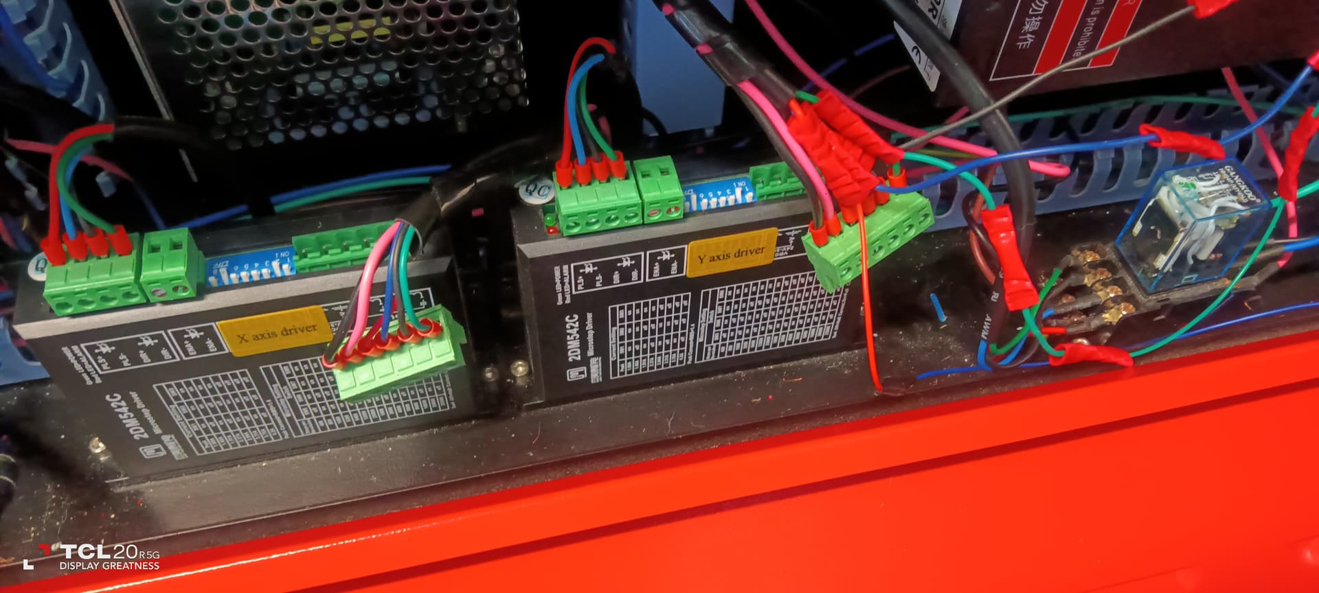
1a. Disconnect terminal blocks at 2A and 2B
1b. Turn on machine
1c. Open Ruida panel to Diagnostics screen
1d. Use a screwdriver or something else metallic to actuate the sensors. Check that X- and Y- limits are showing as active in diagnostics screen.
- Assuming the above is confirmed, then let’s confirm that the laser head is able to actuate the sensors.
2a. Manually actuate both X and Y sensors by moving the laser head towards the sensors. Are you able to see that both sensors are actuated in diagnostics screen?
2b. If not, find out what’s impeding this from happening.
- Once sorted, test with motors plugged in
3a. Replug terminal blocks at 2A and 2B
3b. Turn on machine
3c. Machine should automatically home
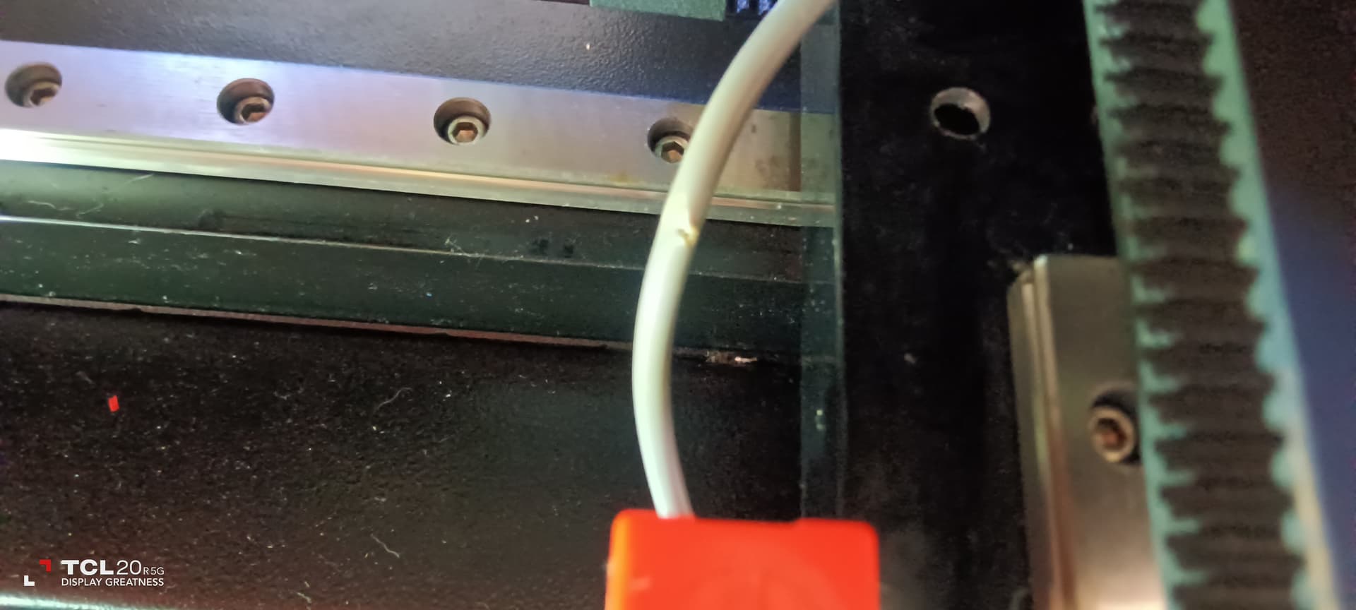
Hi Berainlb… here is what i found while trying to reset the homing position, a cut in the y axis sensor cable , and the laser bed alignment was out, don’t know how or when that happened, how should i adjust it… Sam
I moved the arm back so you can see the hole difference from lh to rh side
Did you determine if this is affecting sensor performance?
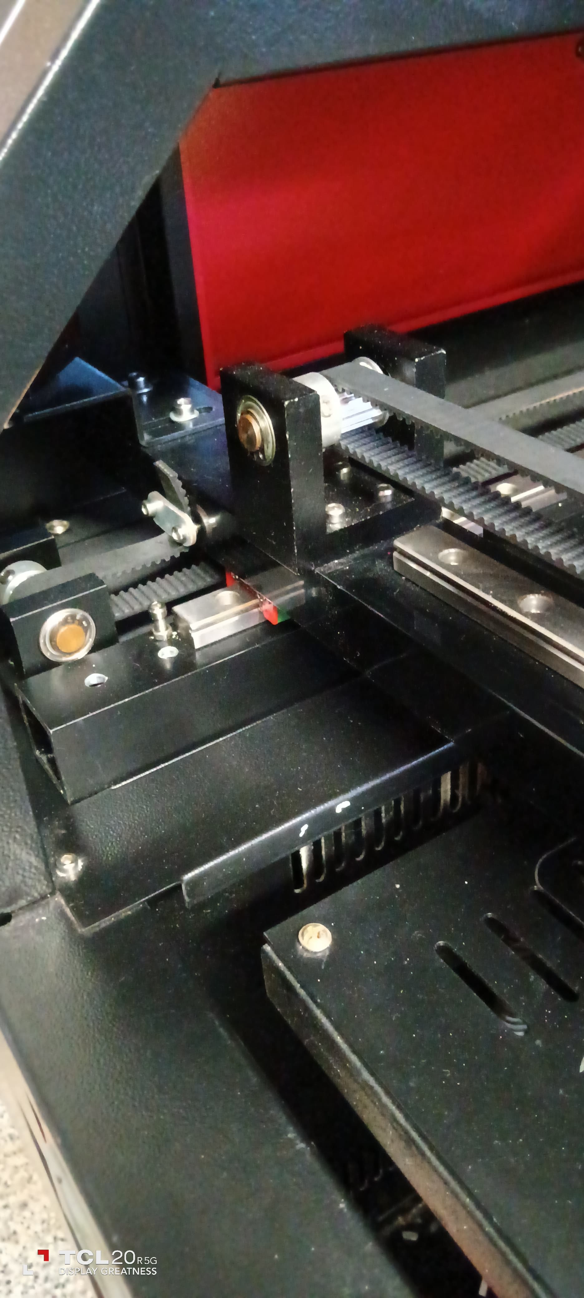
Hard to see what you’re referring to. Are you saying that the X-axis gantry is out of square with the Y-axis rails?
If so, this could have occurred while you were replacing the Y-axis motor or possibly due to a violent collision.
Is this issue preventing sensor actuation?
To remedy, check for what’s preventing free rotation of the Y-axis shaft. This is typically a rigid mechanism that drives the left and right sides of the Y-axis concurrently. You should be able to loosen a grub screw or something similar to allow free rotation on one or both sides. Once done, square the gantry to the frame, then resecure.
the cut in the wiring is not affecting the the sensor light or performance both show up on the Ruida Diagnostic,
The gantry is out of square with the front of the cabinet from the lh side to the rh side, mainly on the rh side so you could be right with the y axis adjustment and yes it did have a violent crash, I will try and adjust the rh side to bring it forward
Hi Berainlb… we are fixed I corrected the alignment with a little brut force just a twist of the gantry and it went back into alignment, i remember hearing a noise when it crashed so I tried something and it worked, it runs beautiful now, just need to reset the homing and we are done, thank you once again for your guidance and support, i learned more about lasers from you than anyone else. Ciao Sam Job Done.
That’s brilliant. Glad you’re up and running.
Getting excited too quick… tried to reset machine and it crashed again and would not stop, hit emergency button and shut it down, also no pulse, nearly there but not quite,
still need your help.
could this be because i reset the gantry arm,…Sam
Did you go through the steps I listed in post #141? If so, what were the results?
Hy Berainlb, no I did not go through those steps as the gantry was on an angle and I wanted to get it square first, after doing this
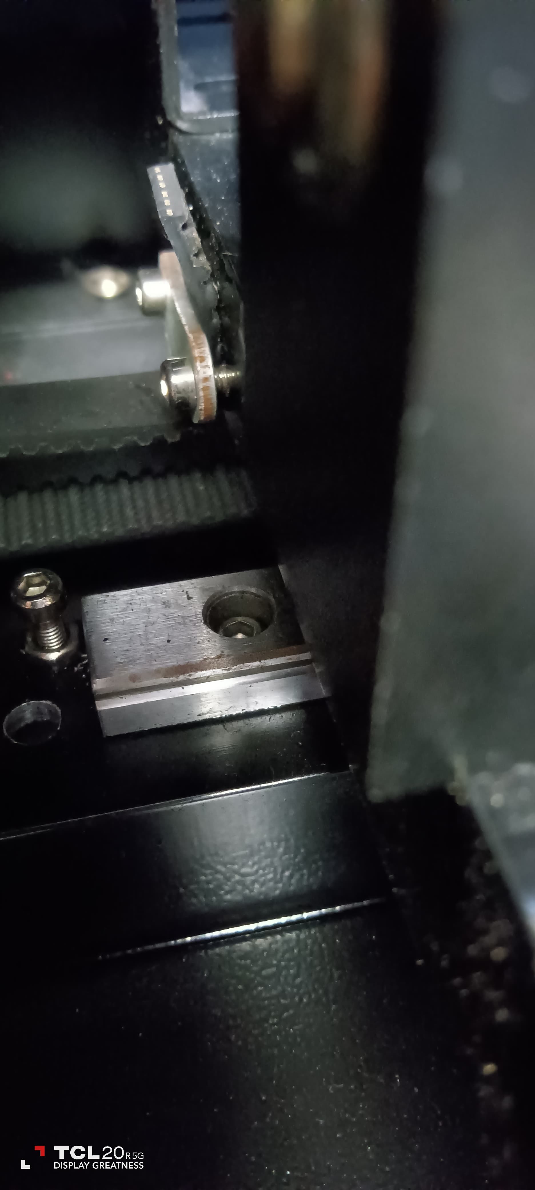
I let the machine home so i could carry out those steps ( post141) that’s when the machine crashed severely and moved the sensor switch on an angle, so I shut down the machine down using the emergency button, also tried the pulse key but no pulse, just wondered if i caused this problem by fixing the gantry… Sam
This is dependent on the cause of the crash which post 141 would have helped identify. Note that post 141 has you essentially disable the stepper motors during the initial testing.
Are you referring to pulsing the laser? If so, I’d advise against this until you have homing working correctly. If the machine went out of square or has alignment issues you’ve almost certainly lost proper mirror alignment so will need to go through the process of realignment from scratch.
Hi Berainlb., carried out tests as asked for
1a disconnected terminal blocks 2a and 2 b
1b turn on machine
1c open Ruida panel
1d tested sensors with screw driver ( both light up) confirmed
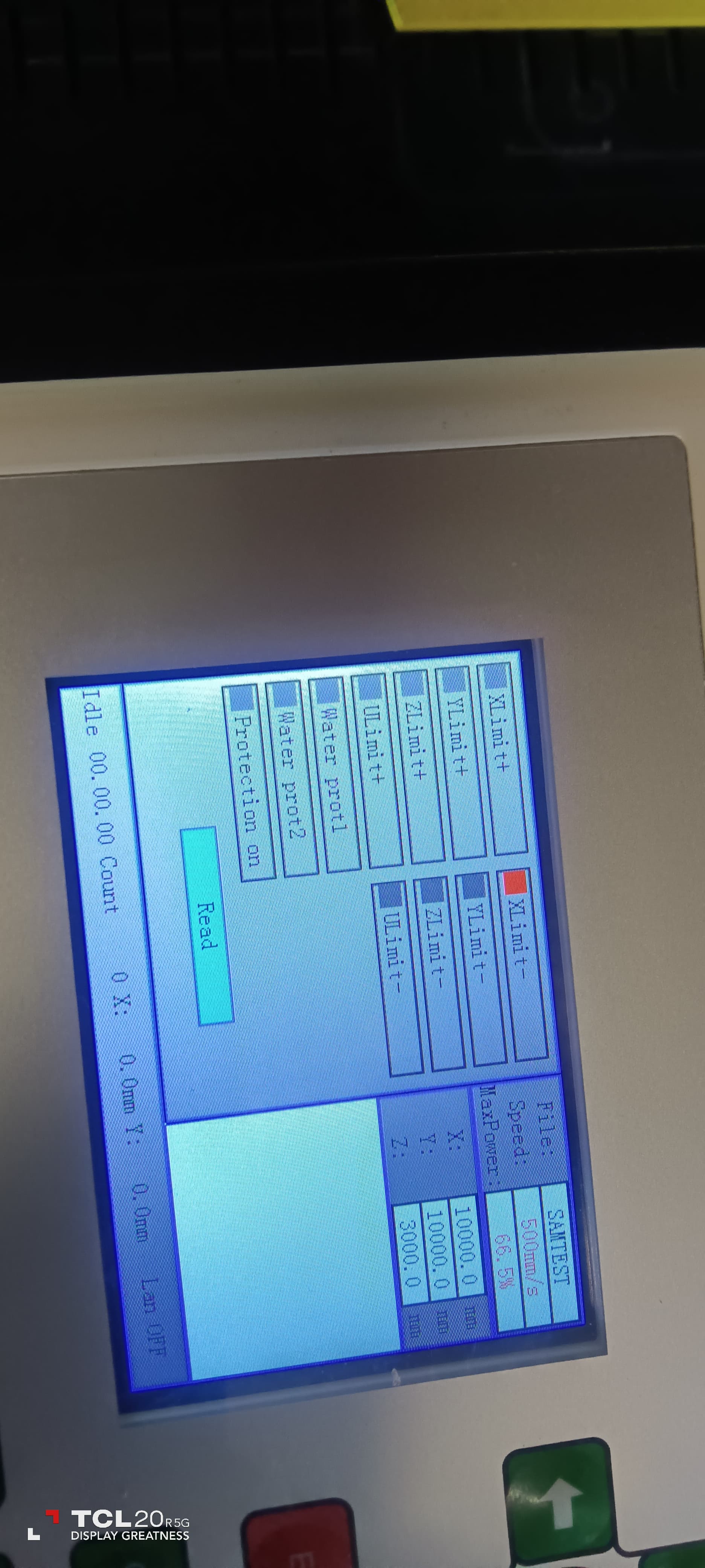
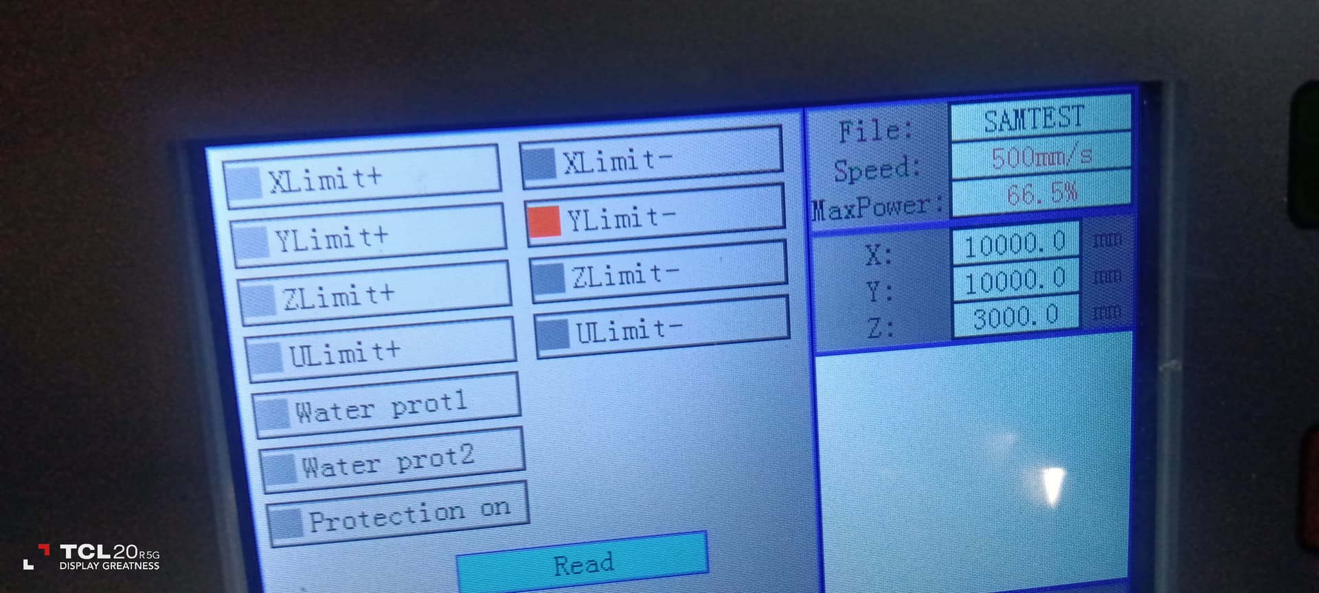
2a manually activate x and y move to position show ruida screen they are showing up only on xl limit for both positions side and upper rh corner, see pics did not test as pics are showing in same box, need your thoughts Sam
Good on the first test.
I want to make sure I understand the results of the second test. You manually moved the laser head to the rear back of the machine where the machine normally homes. You were then able to confirm that both XLimit- and YLimit- were getting actuated without fuss? Is this right?
If so, did you modify anything or adjust anything? I’m asking because if this was the previous condition where it previously crasehd that it should have homed correctly.
If it did not home correctly under these circumstances then may require additional inspection.
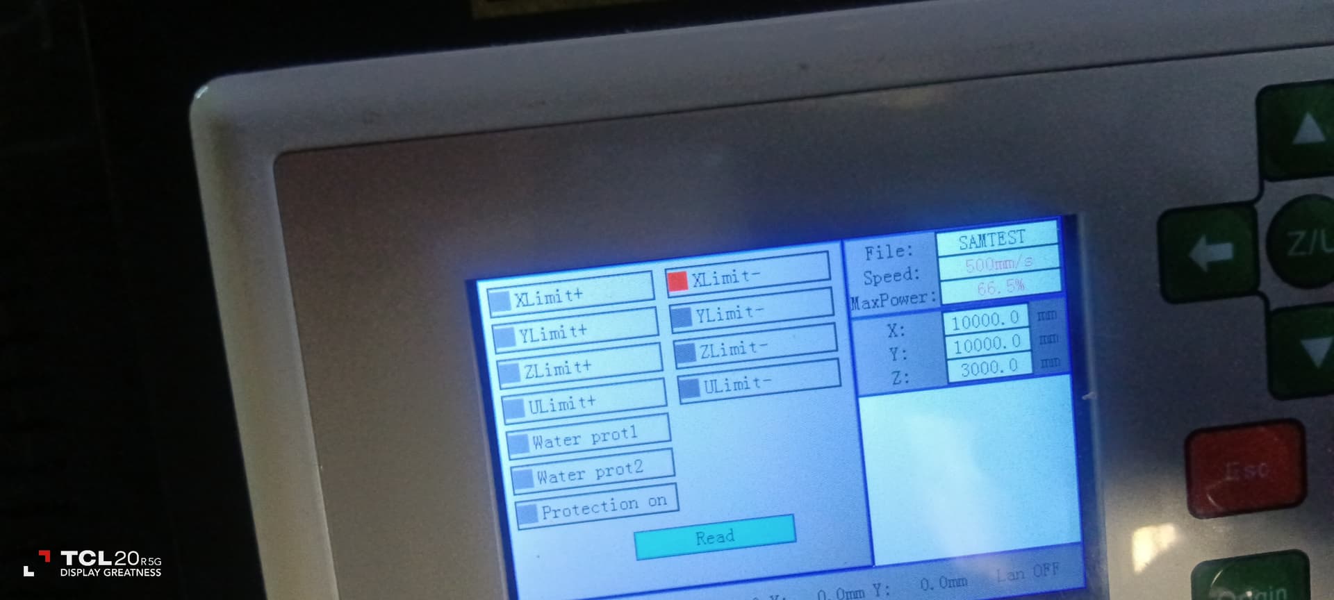
when i manually moved machine to rh side it showed up as x limit, when i manually moved upwards to top rh corner it also show up as x limit
when i touch sensors with screwdriver they show up on screen as x sensor then if i touch y sensor it shows as y sensor
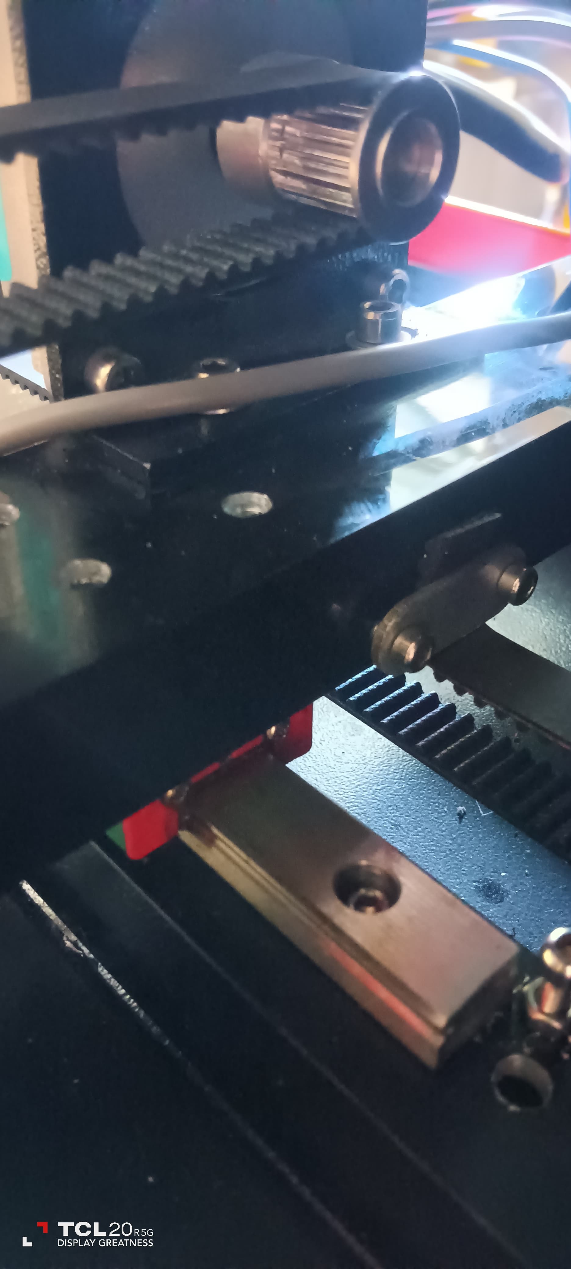
So you’re saying you cannot get Ylimit- to actuate by moving the laser head? You need to identify what’s preventing that from occurring. Is it the placement of the Y sensor? Is the laser head physically unable to reach it?
Once identified, you need to remedy the issue such that the Y limit sensor actuates with the laser head at top right.
Checked both limit sensors again both working and showing correctly on Ruida panel, tightened y sensor, then checked manual movement to homing position and it lights up on on ruida panel as x sensor not y sensor
separately they look ok on the ruida panel
Are you certain it’s showing up as X or is it just that you’re near X when checking?
Push the gantry up to the top of the bed with the head near the middle of the gantry. Y-limit should trigger. If it does not that means something is failing to actuate it.
It should be something on the gantry that’s meant to trigger the sensor.