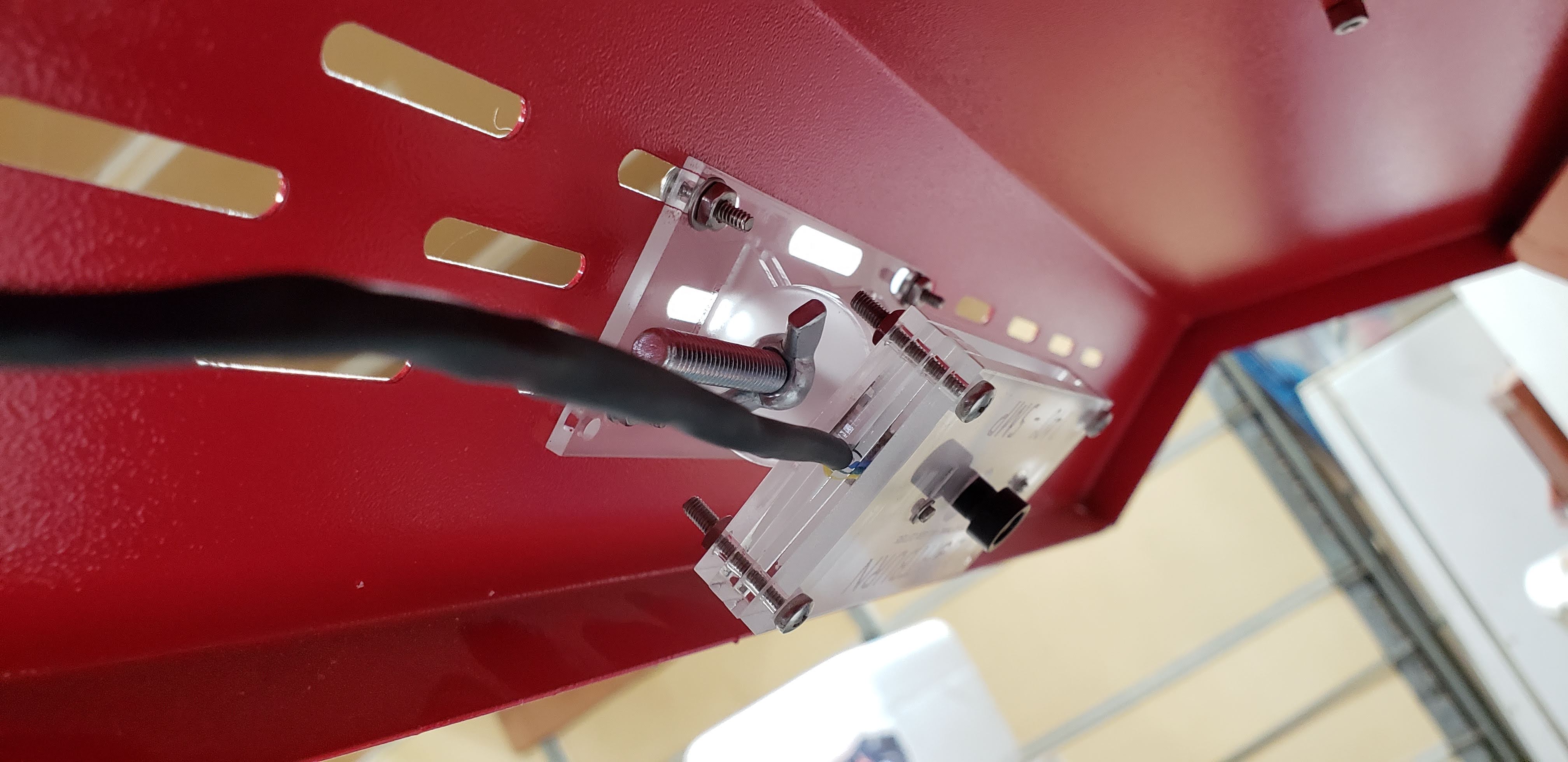
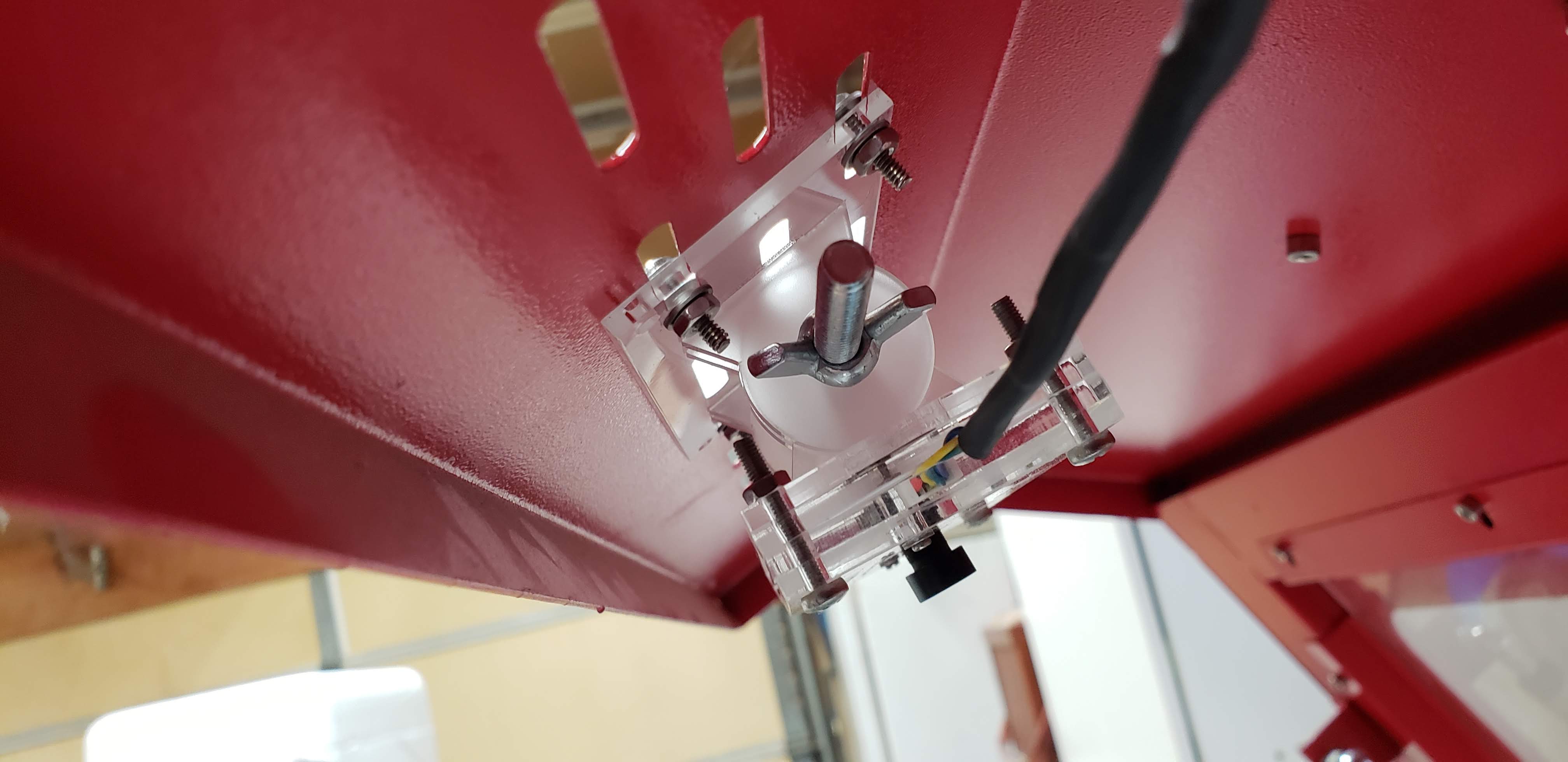
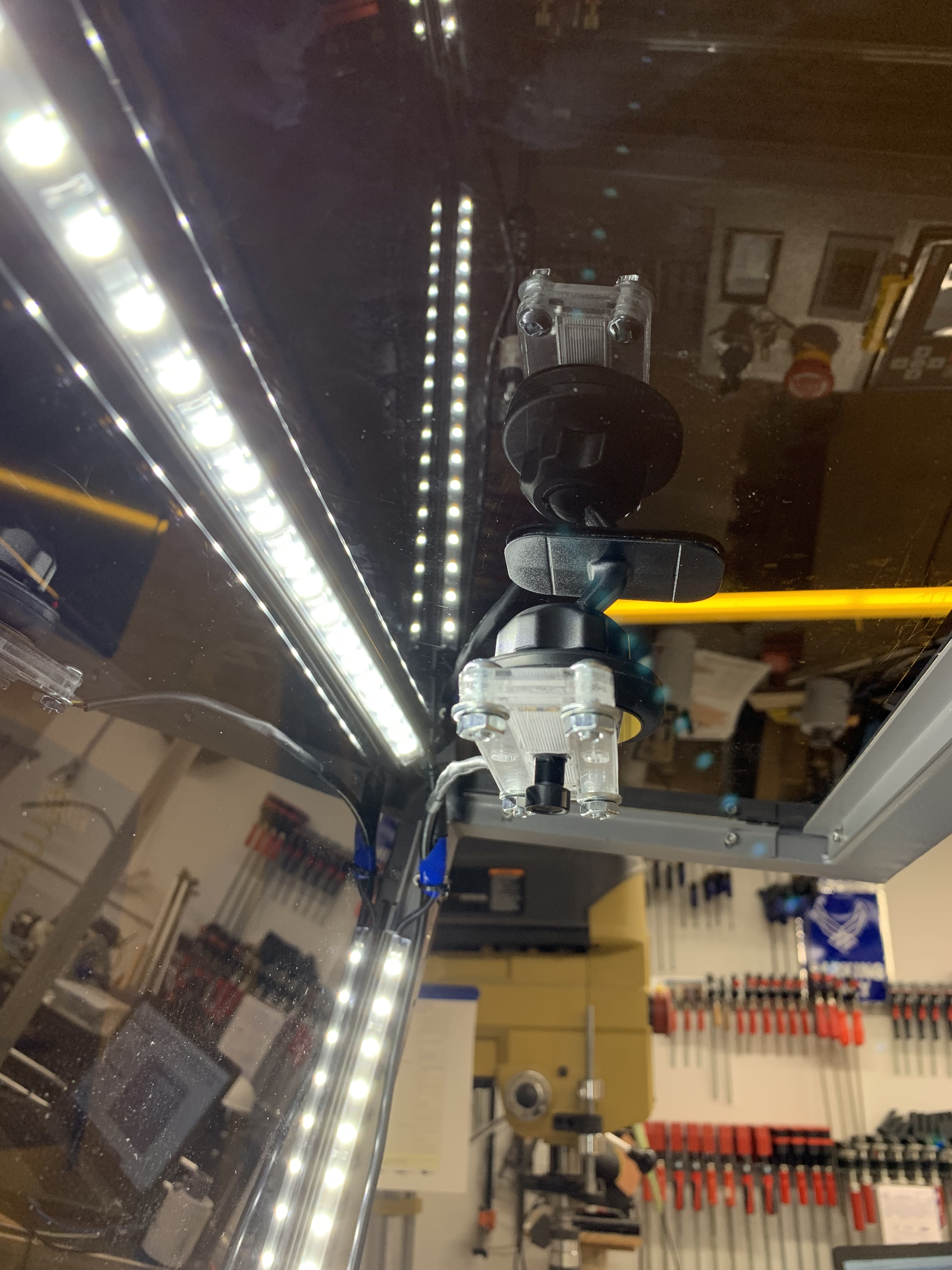
Here’s my take on the camera mount. It is cut from 3mm acrylic and can be adjusted (front to back). On Big Red, I didn’t even have to drill any holes. After dinking around getting the calibration and settings correct, I was surprised how accurate this is. I think it will dramatically change (for the better) my workflow. I would be happy to share the .svg or .lbrn files if anyone is interested.
That’s a nice clean design. I’m more than happy to ask for the svg and lbm files with my thanks. I like the screw-together aspect of it.
I see the tilt is not parallel to the cover, another nice feature of your design. I just recently discovered where I stashed my scraps of acrylic, too!
I’ve been thinking about the workflow too. No more hoping the magnets aren’t in the path of the laser. No more hoping I measured correctly twice and placed the paths properly.
1 Like
Definitely interested… lbrn or SVG… please, and thank you!
CameraMount.lbrn (80.4 KB)
Let me know if you are able to download this - just for my sanity!
6 Likes
Perfect! Thank you… Downloads and opens just fine.
1 Like
Cool. Whew, I wasn’t sure the upload thing in messages worked. Thanks!
1 Like
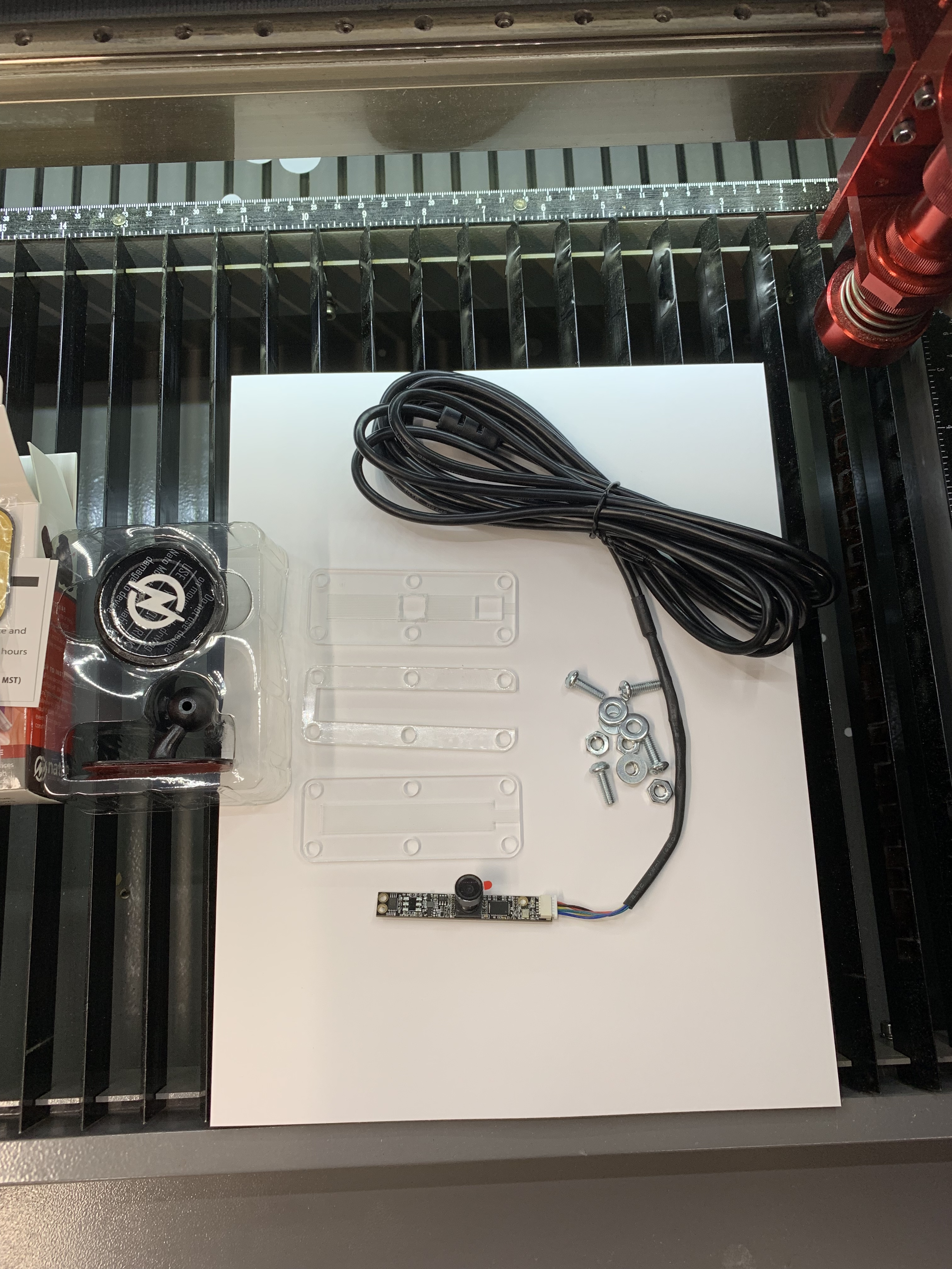
Just so we are clear, the only thing you need to glue are the round pieces to the bases (obvious when you see the cut file). Everything else can be put together with screws, nuts and washers - all of which I was able to find at my local hardware store. Check the kerf offsets on your machine or you might end up with some slop where the round pieces fit into their bases. You want that good and tight for easy glue up.
2 Likes
Great, thanks for the tips… I’ll post photos once it’s installed.
One more q, what wattage did you set your layers for… I’m guessing 60w, but I wanna be certain before I make changes…
Well, I just looked and it would appear that I ran the cuts at 65% and 5 mm/sec. I have a 60w tube which I verified last in the fall. That was probably too much power for 3mm acrylic. I suspect I could have run it at 40% power and it would have cut just as well.
1 Like
Nice design. Thanks for sharing!
Even though the file only shows two of the long thin end pieces, it looks in your picture like you really printed four and stacked two on top of each other at each end?
How did you create the wire pass through hole on the side?
The two very smallest pieces go in front of or in back of the camera module?
Thanks!
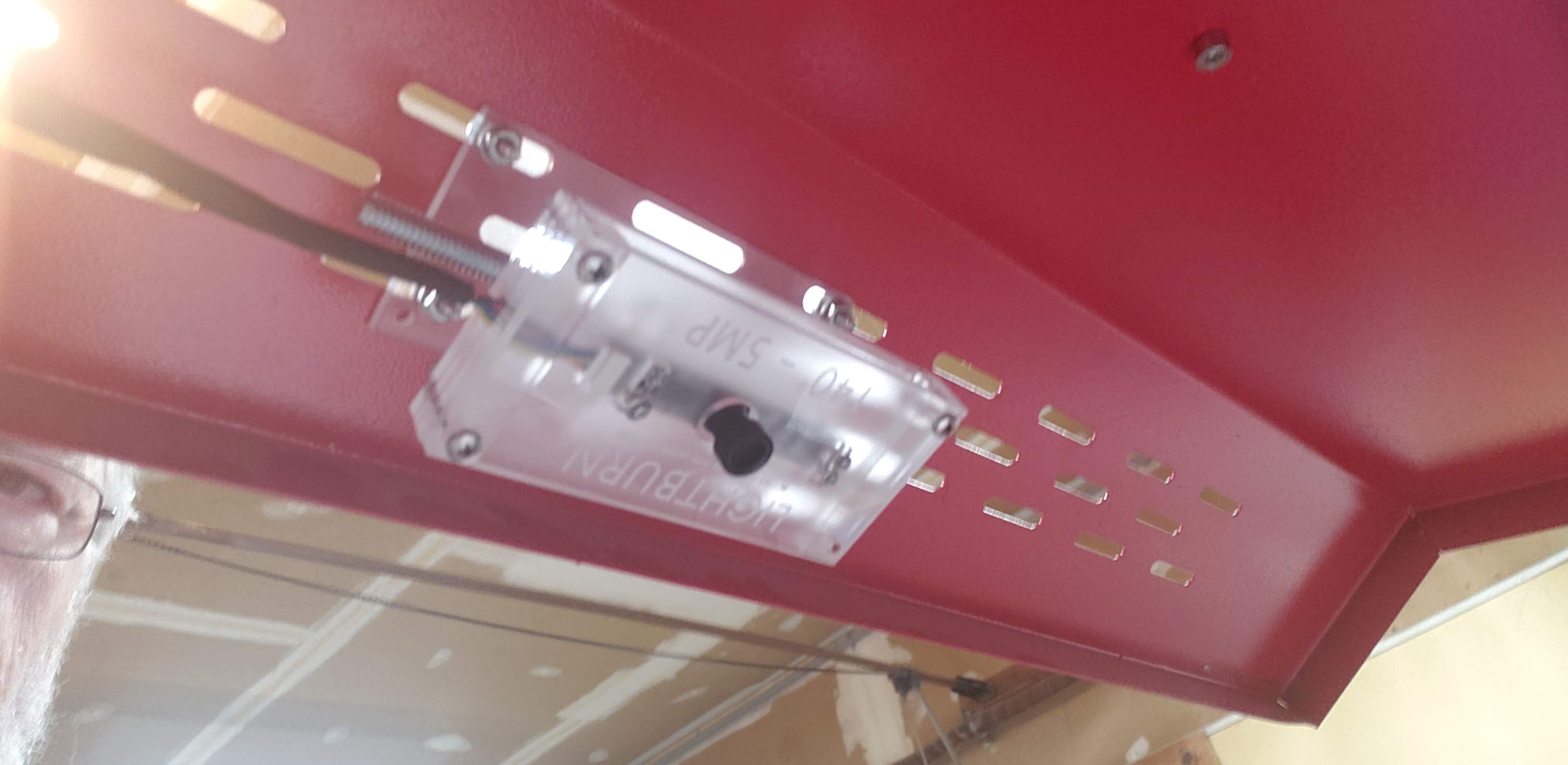
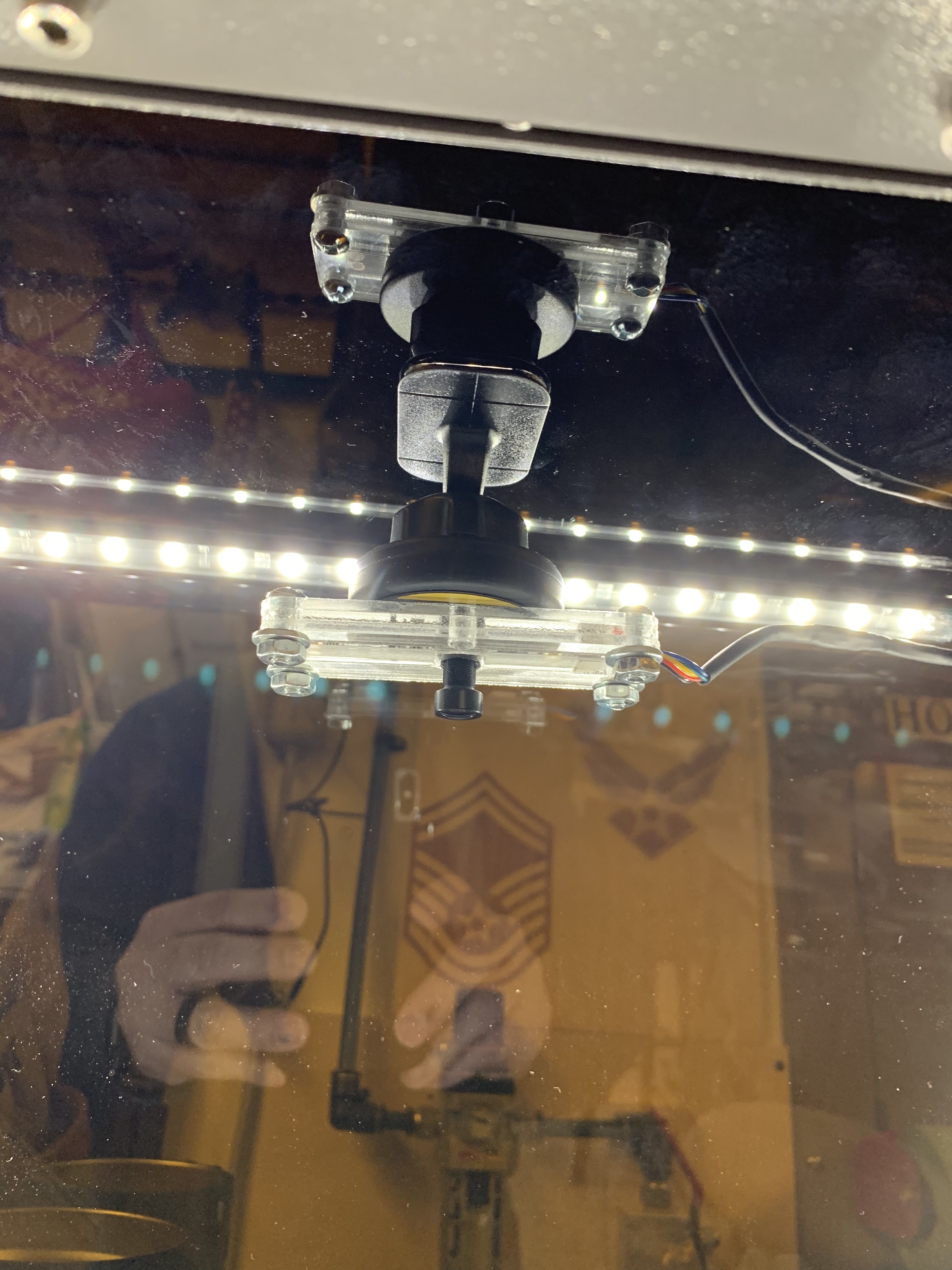
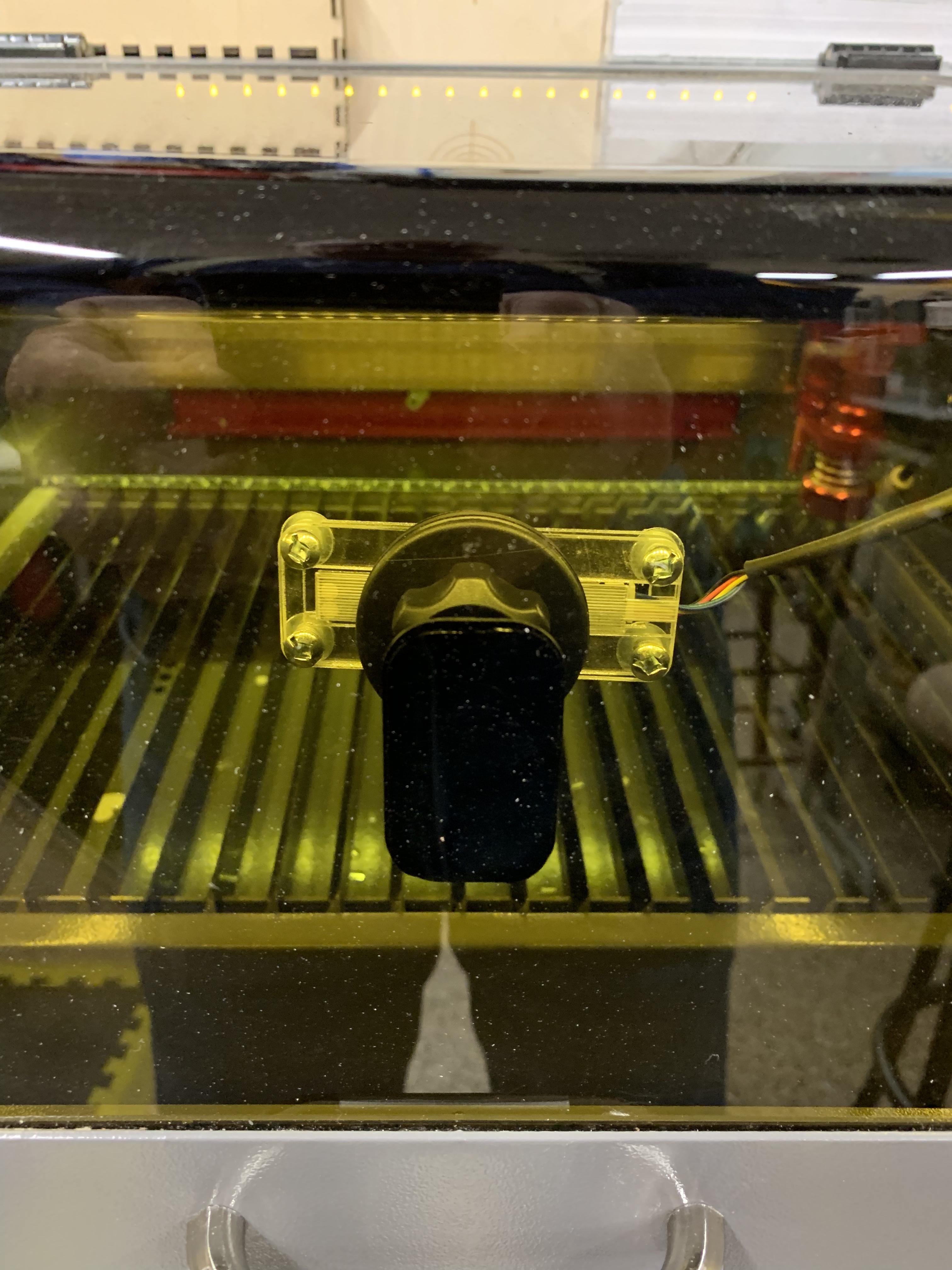
You are correct - an error on my part. There needs to be 2 sets of the narrow pieces for the ends. The 2 tiny pieces are used to stand the PCB board off the front panel that the lens goes through at the screw points. The only thing that is glued together is the round pieces (hinge) that connects the front to the back. On the camera I received there was quite a bit of exposed wire behind the connector that plugs into the PCB. Laid flat and sandwiched between those narrow end pieces, then screwed down snug. This provides a pretty good clamping force for strain relief while eliminating both a hole to pass the wire through or additional screws on the end to keep it aligned.
Another error in the design is the position of the holes for mounting to the lid. I originally thought I would drill holes in the lid, but after looking at it after I built it, I realized that I should have measured the spacing of the “vents” and set the holes accordingly. This resulted in an “on-site engineering change” - I drilled two holes in the plastic back plate so I could use the existing vents. 
Thanks for sharing this Chris - Much prettier than my original, and I like that it’s adjustable.
Thanks for the file. I plan on ordering mine later this month.
Thanks for the file. Waiting on my 120 camera to arrive.
Which lens did you get for the camera?

Yes, inquiring minds want to know … which camera?
The 120deg camera from Lightburn.