Z Axis Moving in Wrong Direction During Probing & Setting Probe Block Height

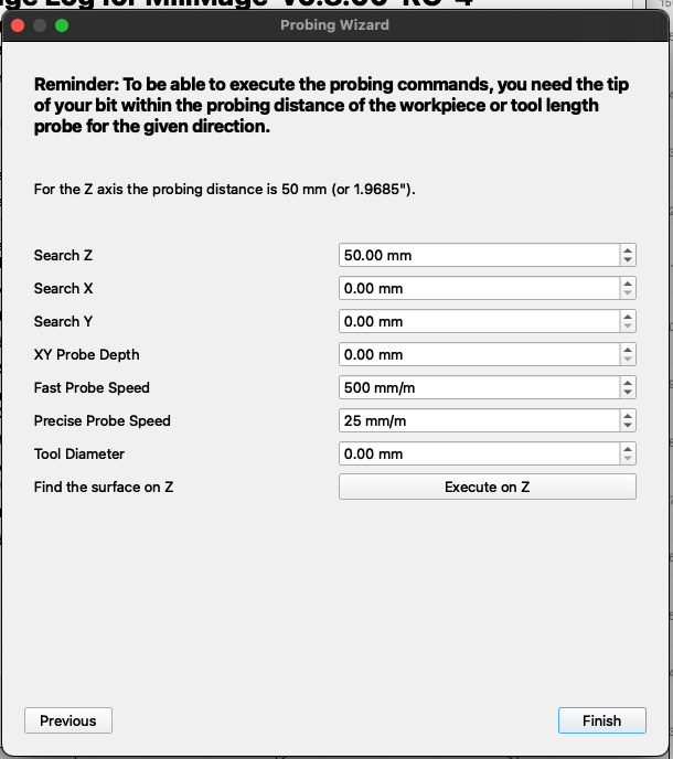
I’ve been using Lightburn with my laser for about 9 months so I’ve figured out just about everything with MillMage but the Z Axis probing. I recently picked up a FoxAlien Masuter3. I built a CNC Plasma cutter so I have limited Z axis knowledge. I’m running 0.8.00 RC-4 but I have issues with 2 things. When I jog and home, everything moves as expected. However when I try to probe for tool length, my Z axis moves up, hits the stop switch, and stops. I’ve tried lowering the Z axis to give it some more travel space before I started probing but the same result. When using Openbuilds or Easel probing works as expected. Z moves in the negative direction until it hits the probe block then parks where I would expect it to.

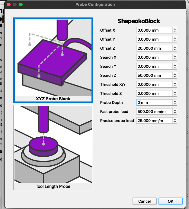
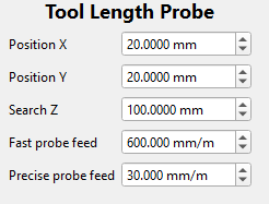
Also, I can’t find where to set the height of the probe block. I tried to post a pic of the Tool Length Probe Configuration but it just shows a link so if the pic doesn’t post, here are the values I can input. All I see is Position X (20 mm), Position Y (20 mm, Search Z (100 mm), Fast Probe Feed (600 mm/m), and Precise probe feed (30 mm/m). Same options are available regardless if I enter through Wizard or Setting. How do you set the height of your probe block?

Here are my GRBL settings
$0=10 ; Step pulse time, microseconds
$1=255 ; Step idle delay, milliseconds
$2=0 ; Step pulse invert, mask
$3=3 ; Step direction invert, mask
$4=0 ; Invert step enable pin, boolean
$5=0 ; Invert limit pins, boolean/mask
$6=0 ; Invert probe pin, boolean
$10=114 ; Status report options, mask
$11=0.010 ; Junction deviation, millimeters
$12=0.002 ; Arc tolerance, millimeters
$13=0 ; Report in inches, boolean (CONTROL needs $13=0)
$20=0 ; Soft limits enable, boolean
$21=1 ; Hard limits enable, boolean
$22=1 ; Homing cycle enable, boolean (Grbl) / mask (GrblHAL)
$23=3 ; Homing direction invert, mask
$24=600.000 ; Homing locate feed rate, mm/min
$25=1000.000 ; Homing search seek rate, mm/min
$26=250 ; Homing switch debounce delay, milliseconds
$27=3.000 ; Homing switch pull-off distance, millimeters
$30=18000 ; Maximum spindle speed, RPM
$31=0 ; Minimum spindle speed, RPM
$32=0 ; Laser-mode enable, boolean
$100=80.000 ; X-axis steps per millimeter
$101=80.000 ; Y-axis steps per millimeter
$102=1600.000 ; Z-axis steps per millimeter
$110=2000.000 ; X-axis maximum rate, mm/min
$111=2000.000 ; Y-axis maximum rate, mm/min
$112=500.000 ; Z-axis maximum rate, mm/min
$120=300.000 ; X-axis acceleration, mm/sec^2
$121=300.000 ; Y-axis acceleration, mm/sec^2
$122=30.000 ; Z-axis acceleration, mm/sec^2
$130=400.000 ; X-axis maximum travel, millimeters
$131=400.000 ; Y-axis maximum travel, millimeters
$132=90.000 ; Z-axis maximum travel, millimeters

The only odd thing I see is this. Normally the Z steps matches X&Y because it is the same motor. Is the Zaxis lead screw different from the other two or use a 20:1 pulley ratio?

It may be okay but I am having difficulty picturing how it is made.

The Z axis is a carriage with a lead screw. X & Y are on belt driven on rails. I’ve checked all 3 axis to make sure that they are correctly calibrated. I just checked them again to confirm they are properly calibrated.

I checked probing function with Openbuilds and Easel and everything works properly in those programs. I only have the reverse probing occurring in MillMage.

Report it to support@lightburnsoftware.com and include a link to this thread. We need their expertise here.

I also had to write my own routine for probing, maybe it is kinda useful for you too:

G91;Restore relative mode
G38.2 Z-30F300 ;Fast probe
G1 Z1F600;Retract slightly
G38.2 Z-2F30;Slow, precise probe
G92 Z19; Set current contact point as Z=19
G90;Restore absolute mode
G1 Z25F600; Retract safely

In case your coordinate system is upside down, you can just flip positive and negative Z axis values. Since my touchplate has thickness of 19mm, I use this offset to set Z in the current position, you can change to yours or set it to zero in case of plasma’s ohmic sensor.

1 Like

This is very helpful. Thank you for your input. I shared the issue with Support as Mike suggested and they made reference to using command G10 L20 P1 that is generated by the wizard. My wizard doesn’t generate that command line so there may be some tweaking yet to do. However, with your input I was able to adjust the values to fit my configuration and it works great for now. I’ll keep you posted if they make any recommendation.

2 Likes

Hey Tim,

You are talking to me on support so I may as well answer here so everyone can see it.

First - Now I see why you are confused about the probe macro and where to set the plate thickness.

Tool Length Probe is for stationary probes that are at a fixed position on the machine. They offset the tool length based on a reference, not actual geometry. You are using a puck, so you should actually be using the XYZ probe block setup, just only in Z - I see where the confusion comes from here and have feedback for the dev team now.

The reason the first move you are seeing with the Tool Length Probe is a positive Z move is its lifting to clear the workspace to go travel over to the tool setter. Where the XYZ probe block it will just start searching wherever Z currently is.

For your block, you would set up the XYZ probe block and put your block thickness in “Offset Z.” Your block setup would look something like this.

In the probe wizard you would do this -

And then you just run execute on Z after jogging to your probe location

Probing and covering all the bases, unfortunately, is really wide and gets complicated quickly. We are working on making this workflow simpler and more straightforward. This post actually gives some insight into potential issues coming, so thank you!!

3 Likes

I was trying to set up my z probe today and ran into the same problem as the OP. The UGS software has separate dialogs for Z probing and XYZ probing so I thought the tool length probe was the z probe. After digging through the documentation file, I think I understand all the setup parameters for the XYZ probe except for the threshold Z and XY. They are not shown in the documentation. And I don’t see where to enter the cutter diameter.
I have both a Z probe pluck and a XYZ probe block and of course the Z heights are different on those. I think it would be advantageous if you could have separate dialogs for just the Z probe and for the XYZ probe. That way one would not have to change the the Z offset every time they use a different probe. Ideally, this should be something you set up once and just use as needed.

Look in the screen shot above. Tool diameter is the second box from the bottom.

We are definitely going to rework probing. This was mainly geared towards getting shapeokos and long mills that come with probes working.

This is the first pass at a lot of UI to see how people will use it and where the gaps are.

Everyone one that has a home build or modified probe setup has a new way of going about it, so we have our work cut out for us.

Can I ask why you need a puck AND a corner block? The corner block can be your puck right? How do you use them differently?

OK, I see, the diameter is not on the configuration page, its on the last page of the wizard. But what is threshold Z and XY on the configuration page?

I use the puck most of the time for bit changes and when working from the workvpiece center. I only use the corner block when I need an accurate xy location when working from that point. To be honest, I purchased a cheap corner block and I got what I paid for. I don’t like it much because its too light and is easily moved by the connecting wire when the spindle moves. If I had one that was more substantial, I would probably use it more. I guess I could turn it upside down when just doing a Z probe and I wouldn’t have to change the Z offset every time.