10-4 Thank you!
the issue is 100% with your TUBE, you have done all the mechanical adjustments, and the lens and mirror cleanings, and there are the electronics, but that’s nowhere near to this issue. Please do not waste your hours on the things that I just mentioned, SIMPLY REPLACE THE TUBE AND YOU ARE ON THE WAY TO LASER CUTTINGS.
What type of material do you use for targets? If thick paper, since we have the same wattage machines can you share speed and power settings?
Here’s where I ended last night. My back said I had doe enough for one day. I’m following Jack’s comments and watched Russ’ video. His machine modifications highlight the shortcomings of the Chinese machines. But I don’t have the capability to make these. Only can be aware of these.
I’ll continue to tweak M1 to M2, and then move on. Again, I have zero up adjustment I can make to M1 so I’m adjusting the diagonal and left-right.
Once I get this done, I’ll move to M2 to M3. Which will be easier for me because I can sit (back and neck issues).
In all of the videos I’ve watched, the is no mention of M3 adjustment. Comments?
Yes, I spoke to OMtech last night. They said the pulses don’t have to be dead center only close but in the same spot. Comment?
I’ll report progress. I greatly appreciate yours and Jack’s help!
Dale
I think I have a way to go before I do that. I’ve had the machine for less than 3 months. Before the manufacturer agrees to send me a new tube, I need to try to get the mirrors as close as I can. According to Jack and Bernd.
Dale
Dale, who is the question addressed to?
If it’s me, I use a very strong paper/thin cardboard, but can’t say what weight or type it is. It fits just fine and stable in the small black target holder from Cloudray. I set the pulse in my Ruida clone to 100-200 ms and start at 8% power (my ignition point is relatively low), for M1. If it’s not enough, I’ll slightly increase the % for M2 and M3.
NB. I exclusively use the machine’s controller to test with.
Thanks Bernd,
I meant what settings did you use to cutout the targets in the file you sent yesterday. And yes, I use my controller to pulse. Speaking of which, I believe we have the same controller. Sometimes when I press the arrow keys to jog, if I hold down the gantry mores until
I release, sometimes I have to press repeatedly to jog. Not sure why or how this changes.
Thanks!
Dale
Excuse me, but that is a statement for which you have no evidence whatsoever. There is a single image, with perhaps a bad impulse, too short a time or too little power… but it shouldn’t cost $300.
If it was true that you “recommend” I should have bought several new tubes, but I still run a small production of a few hours every day with the original tube.
A tube is dead when not enough or no power comes out of it for normal tasks that are calculated for the tube’s nominal power. The full effect can only be achieved when the conditions such as an intact power supply, mirrors and the lens, as well as a correctly aligned laser beam, are met.
This is exactly what @dalek works with.
Don’t bury the horse while it runs. ![]()
ah ok
…no, make sure you don’t use other people’s settings just like that, without being sure that they fit your machine/materials fairly well.
I often test other people’s files and when I load a “diode laser” file it likes to be at 100% power - power must never be 100% on my machine, my max is approx. 60%. (I haven’t throttled down my power supply - yet)
For the paper targets…I mean 100-200mm/s and 13-17.5% power, that’s an average engraving value here with me, but with variations plus and minus.
Could indicate a “difficult” touchpad, they are generally a bit difficult to operate, I rarely use them. I do most of the work with placing objects on the bed with my camera and the small red positioning button, just below the “create/edit text” button.
Check to make sure the lens is not upside down or mis-installed
I figured out the Jog, the button in the center of the arrows allows me to hit a direction arrow to jog incrementally, push it again allows me to jog continuously by holding down on an arrow.
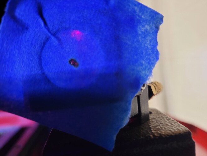
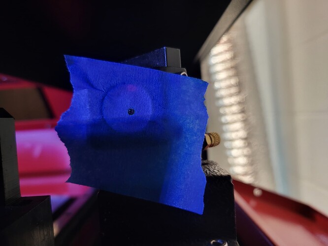
At any rate, I’m attaching 2 photos. First is my M1 to M2 pulse. While they are not dead center, they are on top of each other. I’m stii working om M2 to M3. In back left corner
I’m a little low, in top right I’m a little high both near the center and about 1mm apart. I want to work on this more but a little frustrated that I make minute up down changes and I end both a little higher or a little lower.
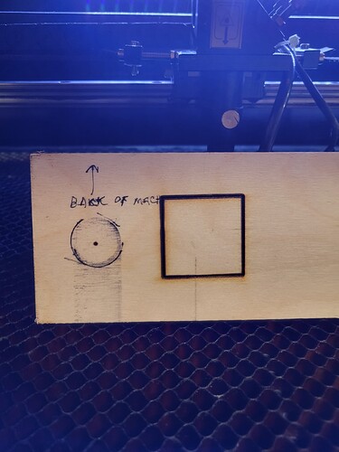
The second photo is a pulse shot of the laser head without the nozzle. Again, off a bit but not hitting the inside when I put the nozzle back on. The image to the right is a 40mm square that I attempted to cut into 1/4" baltic birch. Speed is 6mm/sec, power at 50%; it didn’t cut through. Note the width of the cut line.
What do you suggest?
Thanks!
Dale
Rather hard to interpret, but I think he’s trying to say where they coincide isn’t needed to be in the middle.
You don’t know the beam size… so what is close? If you examine your marks, they have brown/black rings around them. This is part of the beam. If it burnt the target and passed through there would very a very small amount of area burnt.
I guess you need to figure out what close is. The more centered the more accurate the beam path.
The operation is too allow the beam to strike the same place throughout mirrors travel. This ensures the beam is parallel to the Y bearing surface.
Once it leaves m1, it’s fixed, as far as there isn’t much you can do. The maximum amount of adjustment on m1 won’t gain you much when the two mirrors are the closest.
What I’m trying to say so poorly, is that once these are correct that’s it, you have to work with what you have. Since it did work, it still should work.
Russ covers this at about 16:30 into the video… If you mean you don’t have those adjustments, I understand. However the technique is correct and you will have to work with what you have… As I said, it did work and should still be able to get good operation without any massive changes.
Once m1 and m2 are aligned you have to do the best you can with m3… The perfect spot may not be at the center.
Some of us are not confident you have a good tube… without a good tube you can’t really align it.
![]()
Thank you for yours and Bernd’patient assistance. Yes, I spoke with an OMTECH tech guy last night and he said the same thing. I’ve also sent them the same photos as you’ve seen. Like you, they told me the pulse shots didn’t have to be centered but on the same spot. Kind of the same think that American Photonics says. Bring the beams in alignment with the axis, not the mirrors. I will have to think about this to get my head around it.
But, I do feel like my mirrors are aligned better than they were, and future tinkering will improve. The fact remains that I still can’t cut 1/4 inch birch and the cut line is very wide, almost like an offset fill. The lens is correctly focused after running a ramp test, and the beam is slightly off center but, it still should work, albeit not perfect.
Do you think maybe the tube is bad?
Dale
OK, I’m going to try the reverse alignment tool and see how it compares, afteri make sure everything is clean. I’ll let you know.
Dale
Good morning,
Your first picture has the potential for some extra improvements ![]() .
.
Picture 2, the shot without nozzle, - this fire spot is half as big as on your square. If you have the standard nozzle, with the lens in the small reset and you remove it, then your test shot result may not be smaller, it is not logical. The spot is less as in picture 1 and only half from your square - with lens(?)
What are your settings for your test shots?
I would like to see some pictures with different power settings of your M1, from “almost nothing” to a clear fire spot.
I would also like to see a picture with the result of a ramp test and a square 100x100 mm on cardboard or paper with 200mm/s and 17% power (engraved with proper focus).
Do you have other materials that you can test with? (wood or MDF, poplar plywood…)
6.35 mm … I have some plywood that is exterior glued and which I have given up to use for most tasks. The result is not clean and neat and it takes too long to cut.
From 3-4 mm up, I use when I have to use exterior glued material, somewhat the same settings like you, max power (55-60%) and approx. 10mm/sec. And the result is, as I said, not pretty, with many not cut spots.
If you have the exterior-glued material and a laser beam that is not optimal, then we are a little closer to an explanation.
But let’s do the last tests ![]() before the conclusion.
before the conclusion.
Thanks Bernd. I agree that the mirrors need further tweaking. Pulse power for M1 to M2 was 10%. However the far position took several pulses to make a mark. It was getting late and I may have pushed the pulse button a little longer than needed. Yesterday when I did M2 to M3, in the far right, both near and far, 2-3 pulses did nothing so I bumped up to 12%. Concerning M2 to M3, I spent hours getting the pulses to line up. Near is a bit high, far is a bit low, les that a mm apart. I make a very, very slight adjustment up and both move up, same with down adjustments
OMtech recommends I try reverse alignment. I have the tool, so I’ll try this today. I’ll let you know.
Dale
Sorry, I skipped your first question. Yes, the lens was in.
EDIT: Added photo
Since you have the Ruida, there might be a way to set the timing for the pulse in ms. It’s in the configuration on the controller. That helped me a great deal in knowing that the firing was consistent and not relying on how long I held the Pulse button. Once I’d done the ramp test, I fine tuned the focal point by checking the dot size after setting the pulse duration, then reperformed the ramp test not by burning a line, but by moving incrementaly on the sloped substrate until I was able to determine the most finite point. (I’ll post a picture shortly to give you an idea of how it’s done)
EDIT: I set my bed height starting at 12.67mm from nozzle, fired a 10ms pulse, moved the Y axis a few mm’s, raised the bed by 0.45mm and fired a 10ms pulse, repeat and rinse… You can see how the dot got smaller then larger as I passed through the optimal focal point. Hope this helps explain my pseudo-ramp test after I got close with the normal inclined ramp test.
I change mine to this configuration while doing multiple pulsing’s and change it back for normal usage. Check your documentation for your model.
It won’t worry me, some machines don’t even start before 12-15%
I’m doing 12 as well. A new day! See latest M1 to M2, after tightening locknuts. I can’t get dead center but, near and far, the same spot. On to the next one.
Dale


