Afternoon Team
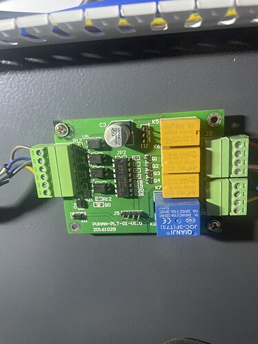
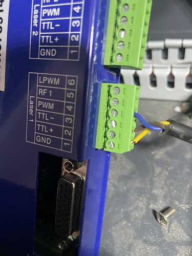
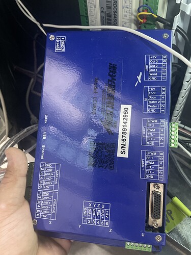
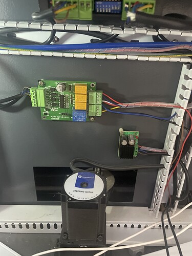
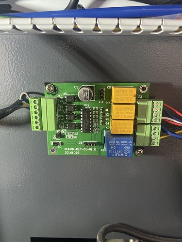
I have a triumph laser with a puhan controller. the logic on it is 5v and what’s getting me is the ruida is 24v. i need help on some of the wiring. and also what is this thing? i know it’s some kind of relay from 5v to 220 but i’m guessing it won’t work with ruida 24v? thanks for any help
Which ruida are you looking to fit? Most have the same basic wiring diagram.
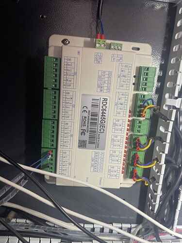
rdc6445g. only thing worrying me is my controller saying 5v and new ruida has 24v on the control side.
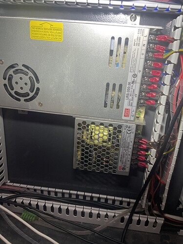
Can you take a full picture of all the parts in your machine? You might have a 24v converter already you can run to the ruida
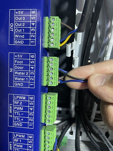
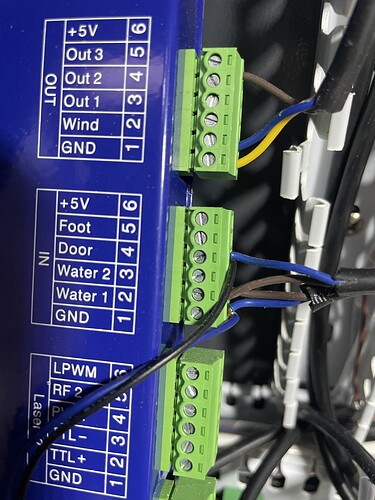
i know i have 24v power supply im talking about how on old lc980s controller on the out section there is a +5v. this is for the wind and on the ruida it’s +24v. and the wire on my machine goes to what looks like a relay. i’m worried the 24v would fry it
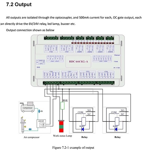
You can run one side of the solaniod in Pin 5 on CN1 (Wind) and then On CN3, pin 6 which is 5v for the other, if you want 5v.
i don’t want 5v just worried it will smoke relay that was on old system that was a 5v coil
Your controller is also 24V… you can see the supply lines marked as such…
The 5V taps on the connectors are usually used for pull up or some low current use.
I would think all the control lines would be able to just be moved to the new controller…
Most of these require you to pull the inputs low and the output usually complete the path to ground…
Supply power might be an issue with the relays you have… This is non-standard for lasers so you will probably be on your own tracing wires. Appears to be made by Puhan and since it’s their laser…
From the looks of it, it has 4 inputs and switches 4 relays… the left appears to be the input, so follow them and see where they lead…
It’s probably a fan air assist type control… probably needs to 5V to operate… but you’ll have to follow the input wires back to the controller and the output to what it’s controlling.
We’re around ![]()
![]()
i understand the 5v is just control voltage. i know that relay is connected to the job status light and the 220 compressor/ and fan.
also thanks for the help so far everyone
All it appears to drive is the optical isolators…
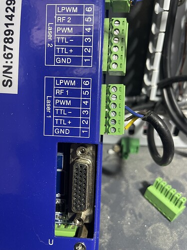
Follow the inputs back to the controller… You will have to know how to hook them up when you swap them out.
Saw your 11 post, looks ok, what’s the issue?
Do you have a Z axes?
Did you save the original machines vendor controller configuration? You will need that…
![]()
What is your current air assist set up? I assume this is the main issue you want assurance on, will the new 24v output fry your 5v relay for the air assist?
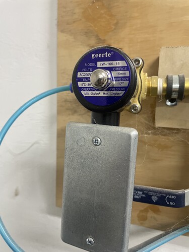
exactly it’s 220v hooked to compressor. the 5v kicks on 220v air soliniod also wondering why my job status lights are on it. i know the door open sensor goes to low voltage side of relay as well.
Is your light multi coloured? I.e green on, safe, red on cutting etc?
yes sir thanks a ton
Right so, the Relay pictured looks like it triggers the different lights on your status lamp. I would run all wires the same to it apart from the +24, as it looks like on the relay its marked for 5v as you said.
Option ide suggest would be to run the +24v line to your existing relay but splice in a IC 7805 or LM7805 voltage regulator which will take your +24v give you a steady +5v output, that way you dont have to worry about moving cables to different pin outs or blowing your relay
agreed i honestly don’t care about the light part of me is thinking i bought a 24v to 220 relay to just use that
