Hi, I’ve a problem when I tried to improve air assist and hope someone can help me with this.
I intended to have a different solenoid for status, high pressure and low pressure. I draw a scheme of what I wanted and saw a post from Dave01 that helped a lot.
Previously I had one solenoid connected to Wind and it activated when I selected air assist for a layer, I also had a the status going to a delay relay to turn of the exhaust a minute after the job ended. Now I connected all the valves to +24V on the same board output and one valve to status through the relay and the other two valves to wind with an ON/ON switch to choose high or low pressure but nothing is working now. I disconnected everything and connected only one valve to wind and +24V but it doesn’t work with air assist selected on LB and it worked like that before I added the other valves.
One thing I noticed is that when I start a job and measure the wind or status and +24V pins with a voltmeter it says 21.5V instead of 24V and I think this is the problem because the valves and the relay need 24V to work.
Thank you and hope someone can explain me what I’m doing wrong.
It would be nice to see how you are using these solenoids or relays…
I have mine setup like the normal ‘advances air assist’ that’s so popular.
I open a solenoid with the “Status” sink, which allows air into the system. There is a restrictor in the line that lowers the output to just enough to keep the lens free from debris.
When you select ‘air’ on the layer and that layer executes, the “Wind” output goes low (sinks), enabling a solenoid that bypasses the restrictor, giving full air pressure. Mine looks something like this
The solenoids should be attached to the 24V line and the negative side going to the Ruida. There should be a small signal diode for back emf when the solenoids field collapses.
Sounds like you are measuring across the solenoid. If the Ruida is not pulling the line down they should read 0 since there is no ‘ground’.
If the Ruida is active (job is running) the Ruida will attempt to pull these pins to ground or complete a path for the 24V of the solenoid to ground. I would think these would work as it’s almost ‘sunk’ the current to pull it to ground.
The Ruida is limited in current and can be sensitive to having emf diodes.
I’d suggest going back to the single solenoid… at least for testing and ensure the Ruida isn’t damaged.
If that works, you can move the single solenoid over to the “Wind” sink and test it there also…
If you have a switch for the lps, leave it off.
Be aware that some of these solenoids have diodes internally. An ohm meter will sort these out.
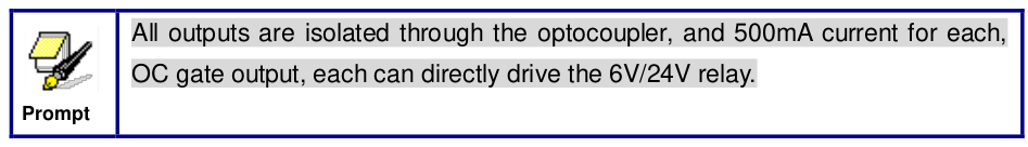
Correct on current limited. They are opto isolated and have a max of 500mA. They suggest a working mA of 300 to 350. Mine pull 375 and no problems so far. If your solenoid is pulling more than the recommended, you could have cooked an opto isolator. Either completely or partially. I have heard of them going bad and passing voltage, but no current but never experienced it to be able to verify. And I will echo the comment of measuring with and without the solenoid connected. If you are using a solenoid with higher draw, you need to have an isolation relay in between the solenoid and controller to limit the current draw. The AirTac are the only ones I can recommend from personal experience with the Ruida controller. If you order them, watch what fitting you order, NP and NPT are NOT the same thread. You might force a plastic thread NPT into an NP fitting, but metal will bind within one thread turn.
My air assist is similar but a little more complex, will post the diagram when I can go the other computer.
I didn’t understand what you’re saying her “If the Ruida is not pulling the line down they should read 0 since there is no ‘ground’.” When I’m not running a job I measure the +24V and wind or status pin with a voltmeter it reads 24V and the solenoid LED is on but the valve is closed as it should, when I start a job the valve doesn’t open and the LED seems to dim, the voltmeter reads 21.5V on the pin with air assist active on LB.
I have diodes on the solenoids because it’s advised.
I already tested with only one solenoid in the wind output like I had when I bought the laser but now that doesn’t work either and I don’t know what to do. The valve LED turns on when I connect it to the +24V and wind (this didn’t happen before and it only turned on when I started a job with air assist) and the solenoid wont turn on with the job.
Is this a problem with the Ruida controler? Seems strange because I didn’t do anything wrong just connected a few wires. The Ruida is a 6445S(ED)
I hope I was clear whit this information and thank you for trying to help!
Thank you for your reply Dave.
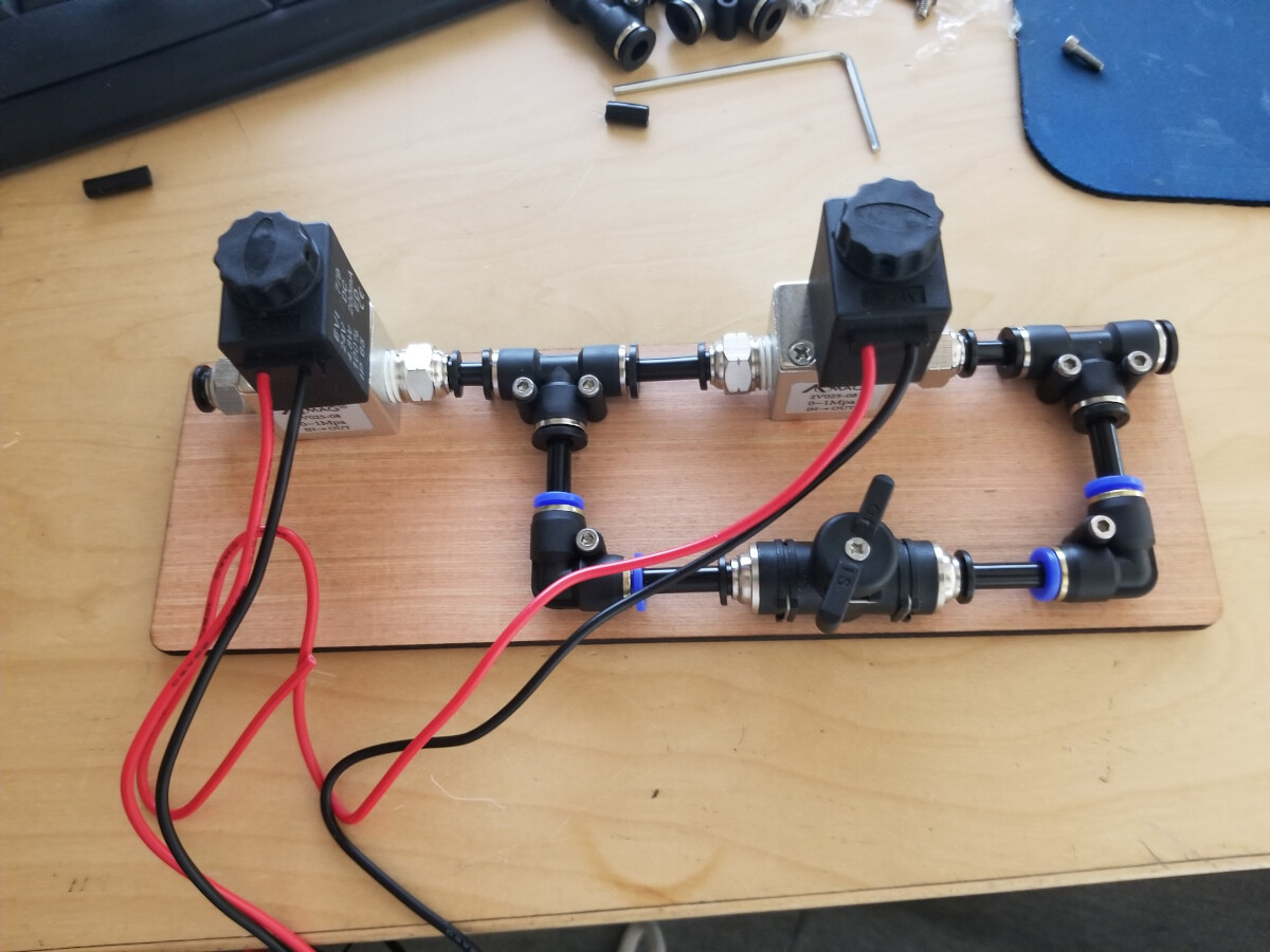
The solenoids I bought are from AirTac, the model is 3V21008NCBG, I will try to see how much amps they pull but I think it’s less than 500mA.
These is the link to the valves:
These valves are similar to the original one that came with the laser, and these ones even have less watts.
But is there a problem connecting the three solenoid valves and the two relays to the +24V pin in the Ruida CN1? Was this the thing I did wrong? Because with your explanation it makes sense that everything together is pulling more than 500mA
That and air pressure. The one I used, I can’t find current info so it’s been superseded by something, will operate at 0 psi. Your valve specs say it has to have 21psi., WAY to high for a regulated down flow for the laser. You could simply be fighting an air pressure issue now that it’s broke in. If you are operating off a diaphragm or any other low pressure pump, you need to get something that will operate at or below 3 psi. I made the same mistake with my first attempt at building an air assist manifold.
Each output pin on the controller has a maximum current spec. If the solenoids / relays / valves require more current than the controller can handle, they won’t work correctly.
The solenoid valve was rated 24 V / 4.8 W = 200 mA, which is less than the 300 mA rating for the Ruida KT332N. I had a solid state relay in my parts box, so I used it anyway:
Check the total current required by everything you have connected to each controller pin to be sure it’s within the spec for your controller.
Unfortunatly it’s not a pressure problem and I’m afraid the ruida opto is fried as you said, should I have used a separate power source for the +24V on the valves and relays and just the wind and status pins on the board instead of plugging everything to the board directly? I use a big air compressor at 3 bars (about 45psi) for cutting (high pressure) and have a bypass for engraving. Everything worked fine with just one valve, after connecting the three and the relays to the board nothing work not even the valve that used to work.
Thank you very much for trying to help me!
Thank you for your reply!
I didn’t think of the maximum amps draw before but it make sense that was the cause of the problem as all the valves plus the relays definitely draw more than 500mA from the +24V pin.
This means I fried my board or is there a way to make it work? Was thinking about buying a separate 24V power source just for the valves and the relays but now even one valve that I always had working in the board isn’t activated by the wind pin either.
First, it is not clear from the Ruida documents what limit, if any, applies to the +24 V supply pins on the controller. As a result, I connect high-current devices directly to the +24 V power supply, rather than the (much more convenient) controller pin.
Second, the 300 mA limit I mentioned applies to each controller output pin like AuxAir. Loading those pins beyond the spec may not damage them, but they cannot switch a higher current. Because I have a box of solid state relays, I do not wire any solenoids / valves / whatever directly to the controller.
So the controller drives only the minimal load for the solid state relays; the +24 V for the input side of the relays can come from the controller. Those relays, in turn, drive the actual loads.
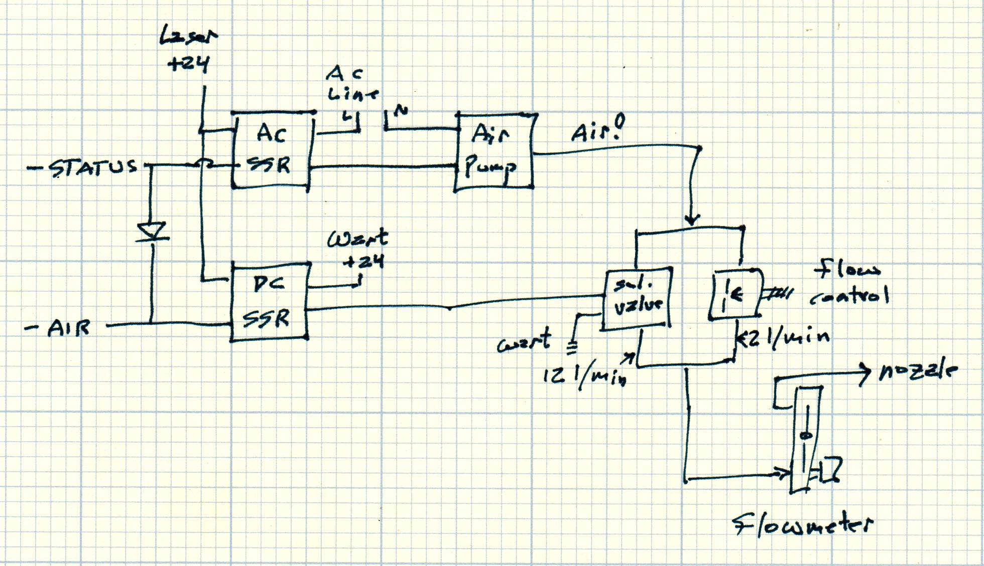
The crude diagram for my dual-flow air assist shows what’s going on:
The air pump runs from the 120 VAC power line, so it requires an AC SSR.
I installed a separate 24 VDC wall wart to run the solenoid valves, so the output side of the DC SSR connects between that and the high-flow solenoid valve.
The controller outputs are more durable than you think, so when you load them properly they’ll probably still work fine.
Thank you very much, your answer made me feel calmer and more positive because it shouldn’t be a problem on the board! As this limit only apply to the Status and Wind pins i don’t think I’ve overload them.
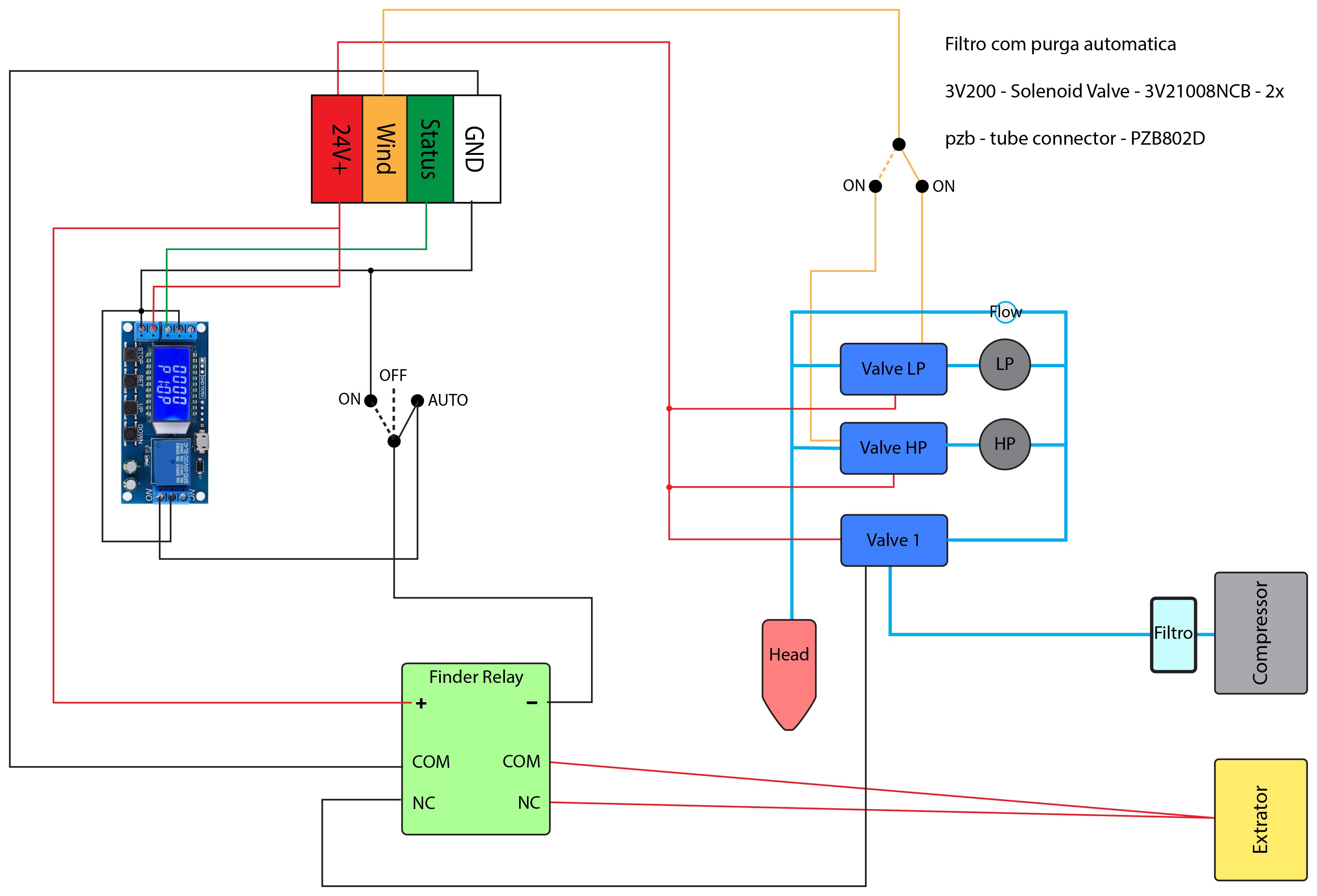
I will post my diagram so you can see how I connected everything. But if everything is ok with the board I will try to buy some relays to connect the other valves.
This is how everything is supposed to be connected but after I connected everything and it didn’t work I disconnected and used only one valve on the wind and +24V to test and it also stopped working ( it worked previously)
If you’re not scared of a soldering iron, the opto isolators are individual components. I have head of several cases where owners have cracked the case and move one from an unused output over to the WIND terminal.
That’s exactly what I was searching now and came across this post and a couple more saying the same:
The user solved the problem by soldering it and I’m thinking about taking them out of OUT1 and OUT2 and soldering them to Status and Wind. One important thing is what is recommended for this not to happen again! It’s better to have relays or a separate power supply for the +24V?
@Dave01 can you please send me a photo of your air assist as I think its similar to mine? I saw the one you have on Google Drive but if you can show how it’s connected or a diagram of it like mine it would be great.
I don’t buy into the Chinese statement of the optical isolator. I have yet to find an optical isolator that will handle 500mA@24V … If you can find one, I’d love to see it… that’s 12W if my math is right.
If you follow those who have ‘blown’ them out, it’s a transistor the optical isolator turns on…
The Ruida manual draws the output as optically isolated in the manual, but it seems those who have ‘broken’ them have proven the driver is a transistor.
I have a bunch of Ruida manuals, but this says it in English. Even though it only says it’s isolated, not that the isolator can sink 500mA.
As it’s written, it is how the Ruida handles the output (actually a current ‘sink’). If you measure across it this way, there is no difference across the coil to measure.
If you close the switch or complete the ground, then you will measure 24V across it, if it can supply the current.
If you are measuring less there seems some problem with the Ruida outputs. You have pretty much confirmed that as it worked before and when you return to the configuration it no longer works.
I’ll hunt around and see if I can find one of the articles on replacing the driver…
You can check on the RDWorks forum if you want detailed info on swapping the opto couplers. That is primarily a Ruida forum.
The pic on my google Mod Page is about the best I have on my manifold. The wiring is pretty simple. STATUS to the main solenoid that enables the minimal bypass when ever it’s on. High and low are switch selectable on my Control Console. It’s the same panel as the Control Console 03 pic, I just added a SPDT switch to make the selection, and it is fed from the WIND terminal. I’m literally running every low voltage circuit from the factory 24V power supply. My wiring is pretty much the same as Russ has with the Ultimate Air Assist package sold on Cloudray, I just swapped the relay for the compressor with an air solenoid as I pull from a large higher pressure system. I do knock the pressure down before it gets to that manifold. Didn’t at first, and 120 - 150 psi is kinda hard on the little regulators and solenoids.
The power supply has a 5V feed, but in tracing something else, I discovered the ONLY thing on the 5V was the red dot. I added a resistor and switched it to 24V for consistency… and promptly broke the wire in the drag chain three months later. Never bothered to fix it.
Hope that helps, drop me a line or a comment here if you have any more questions.
Russ’ wiring diagram for his Ultimate Air Assist in on Cloudray’s web site, second pic down. I couldn’t tell you what post it was on the RDWorks forum for the component swap, but pop in there with the question on swapping the opto couplers and you will get a pretty quick and sometimes TOO detailed an answer. A couple of the guys on there are the electrical engineer types.
The 500mA is a surge or startup value, hence the 300 to 350 mA operating current. My AirTac solenoid pulls between 360 and 375 mA depending on what meter I use and which solenoid I’m checking. None of them are real high dollar calibrated meters. But going on three years and no problems so I think I’m good.
FYI, the 500 and 300 - 350 come straight from the Ruida IT department.