Could the process described in the video:
Cutting a single project larger your laser (pass-through version) - YouTube
be used in a xTool D1 laser unit?
1 Like
Yes. That technique should work fine with any laser. However, you’ll need to find a way to have the work material be able to span an area larger than your laser frame and stay in focus.
For the D1 you may be able to elevate the legs. Or if the material can pass under the frame then you’re fine. You’ll need to make sure you have enough adjustability for the focus height as well.
Thanks a lot. I hope that will work. It seems there are not too much experience in this application and the joint use of the D1 and LB at this time. I’ll try that as soon as I get the D1 delivered.
The necessary changes to D1 firmware enabling LightBurn to work are all very recent and they’ve made a couple of revisions to the firmware since then. Seems xTool has worked out most of the issues with the firmware at this point.
However, in terms of Print and Cut it should work the same way as it does for every other laser so you should be fine.
Well either I am missing something or this large area idea does not work with the D1.
This is what I got so far, which actually doesn’t seem to be related to the D1, but it may be.
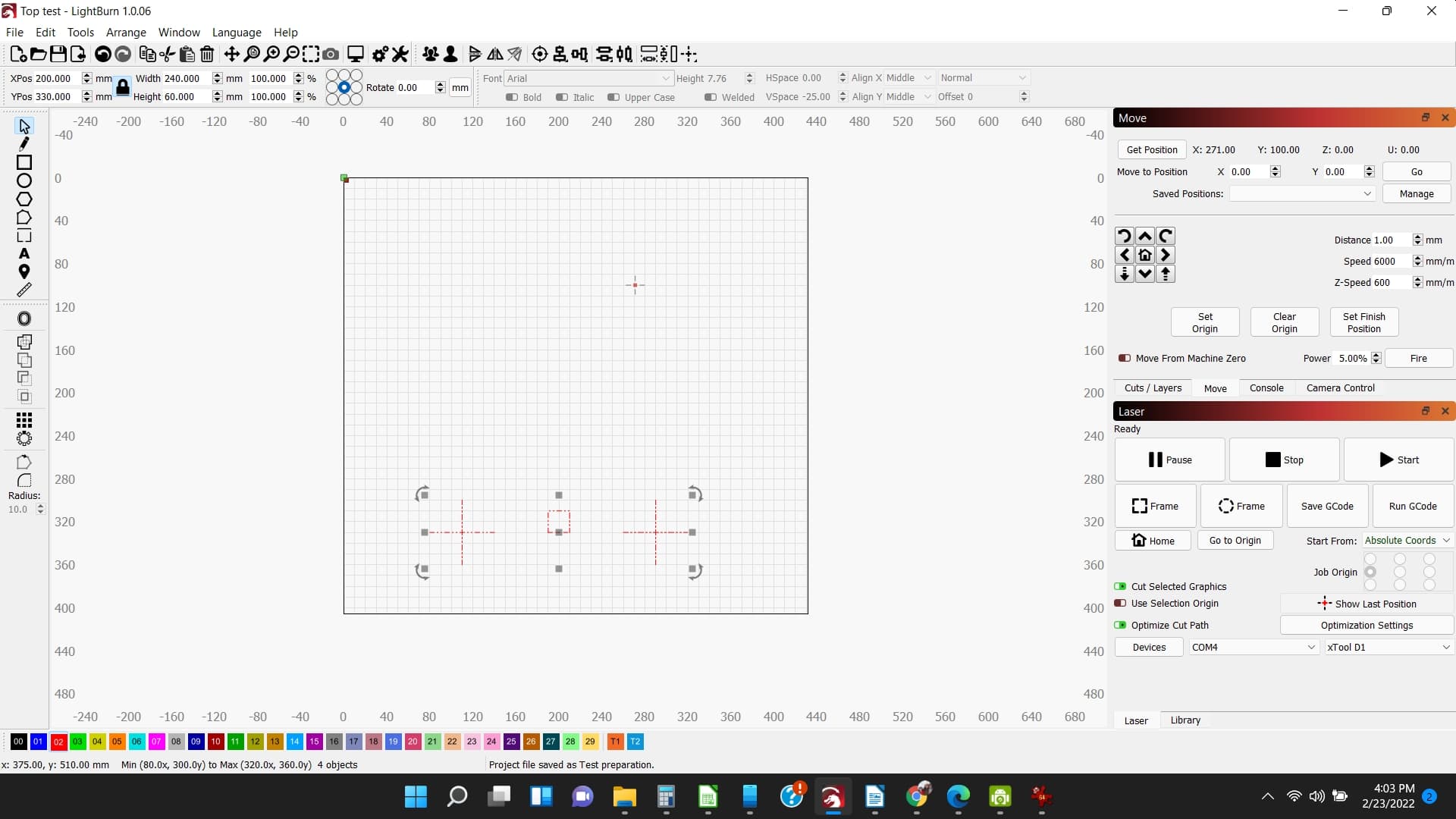
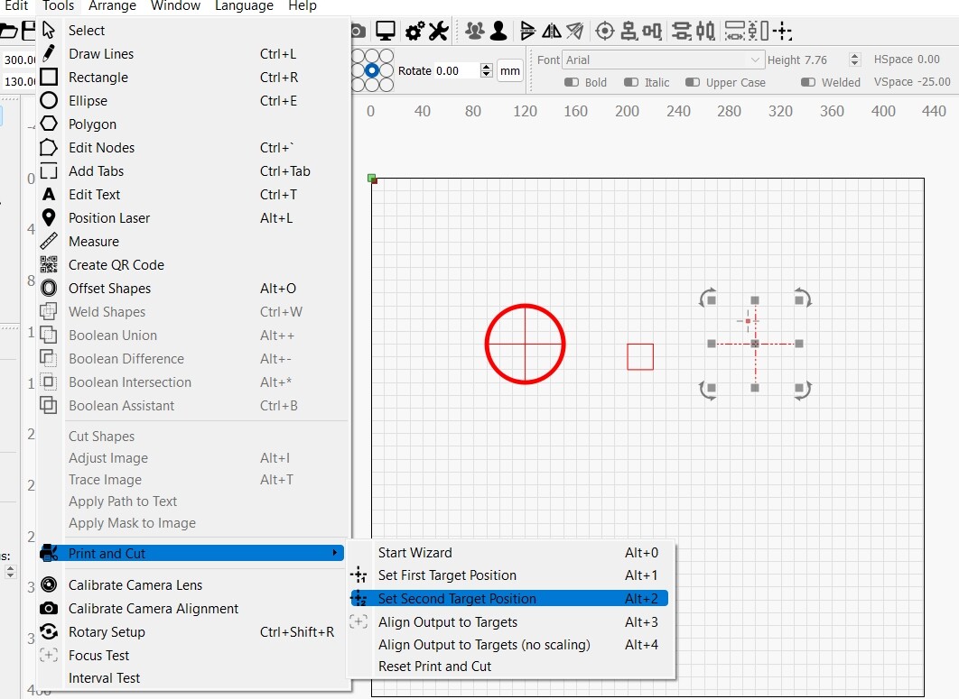
Just for the sake of testing, and considering the key part to align a large piece is to tell the LB where the target positions are, I just draw a 80 x 80 mm box and draw two circles as targets, separated 60mm from each other. Then I manually (physically) moved the laser to one position in the unit, selected it as the first target position. Again, I moved the laser to another location, selected the second circle in LB as the second target position, but I got a message saying “insufficient separation between targets”. I am using LB 1.0.06, Lasebox 1.2.0, and D1 FW 40.30.002.01.B1.
Can you help me, please?
There’s nothing that relies on specific capabilities of the D1 for this to work.
Are you using jogging controls to do this or manipulating by hand? This has to be done with jogging controls.
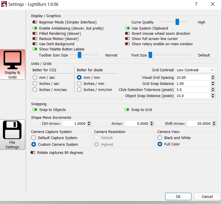
Also, you need to be using Absolute Coords if you are not now.
You may want to review these steps that Oz documented as it’s a good explanation of the steps required.
1 Like
As I thought. I was missing something. I was not using the jog. Now it looks good. Thank you very much for your help.
1 Like
Now that it seems I got a hand on it, the results are not good at all. I have a curiosity to start with. According to the video, once I select the first target, I get a red circle but when I go back to select the first target is not greyed. However, once I select the second target, then both are greyed. Not a big deal, but when something doe not work anything is suspicious. Now, here is the problem. I tried too many times, following the video, but I cannot get the work aligned. The targets in the second part are all over the place, not even consistently shifted. Again I hope I am missing something, but sure enough, I need help. I am running LB with an xTool D1. Attached are the files I try to align

Bottom test.lbrn2 (6.3 KB)
Top test.lbrn2 (6.4 KB)
. It seems to me that the system is ignoring the targets and drawing the second part as it is set in the LB base table
Provide 2 things please:
- a photo of the failed cut
- document step by step in as much detail as possible what you are doing.
Here are the procedure and pictures of each step.
The objective of the test is to verify that the system LB-xTool D1 is capable of producing cuts or engravings larger than the size of the bed.
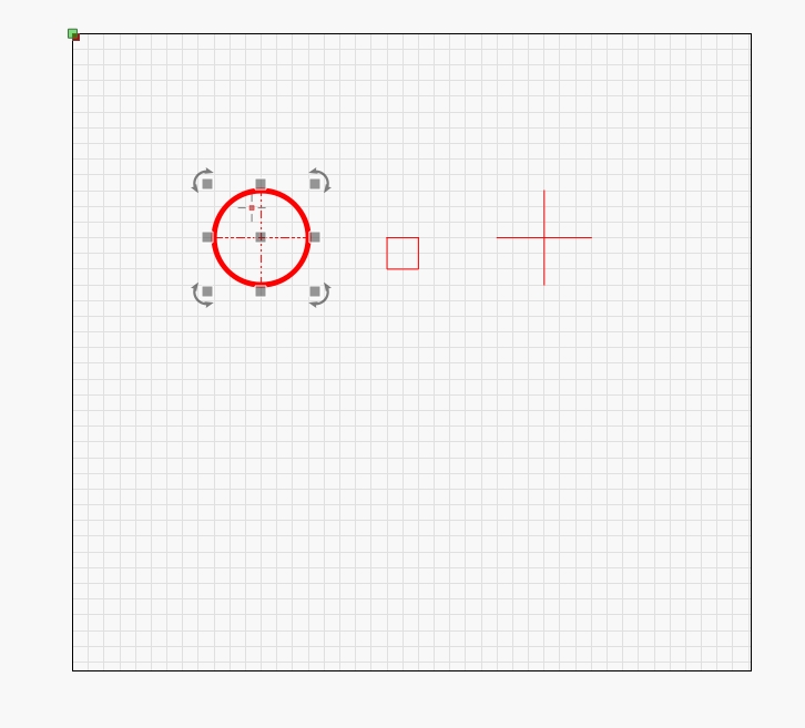
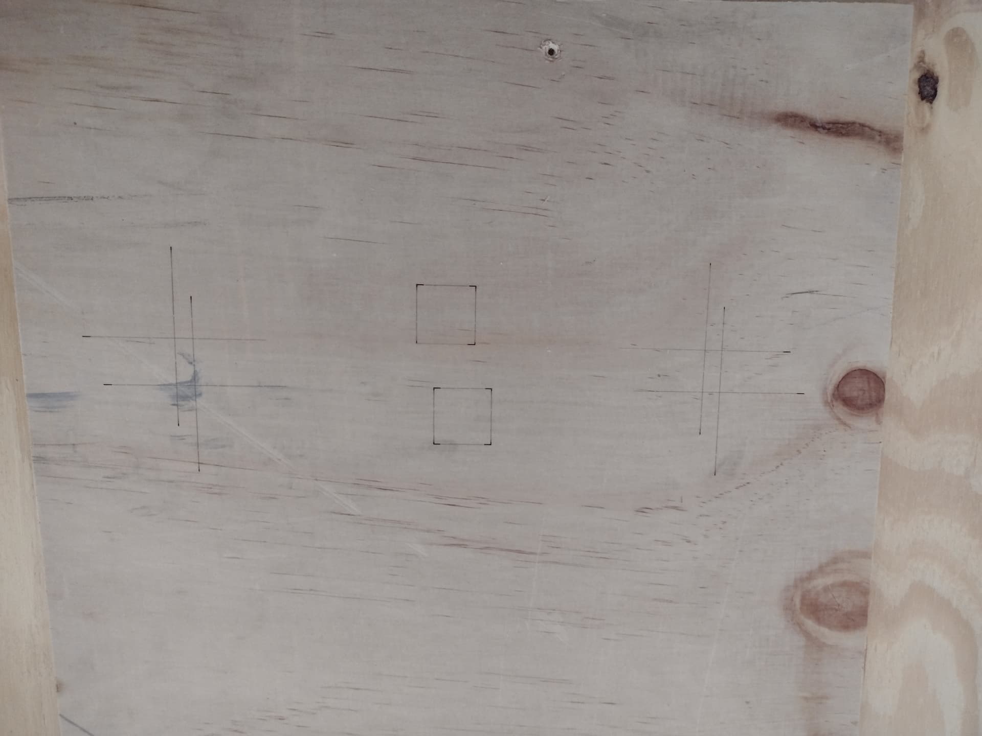
As proof of concept, I split a rectangle into two parts and added a couple of crosshairs.
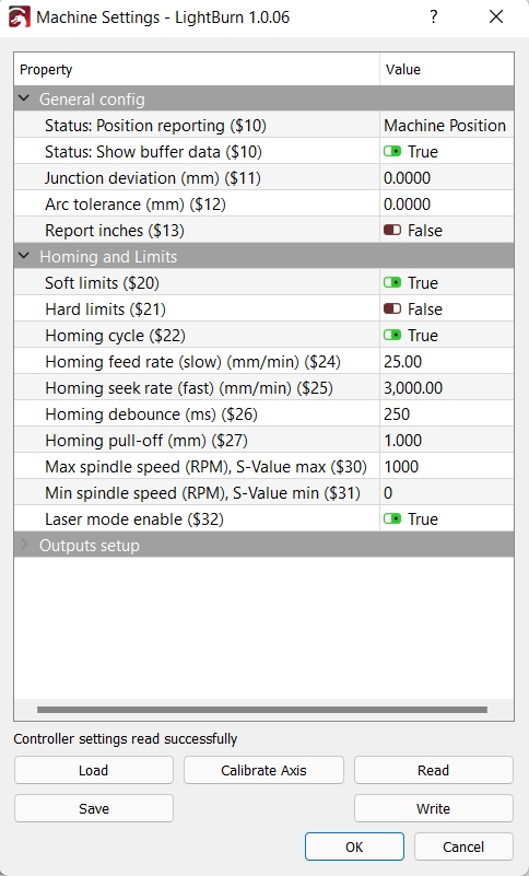
Just for background information, I will start with the configurations.
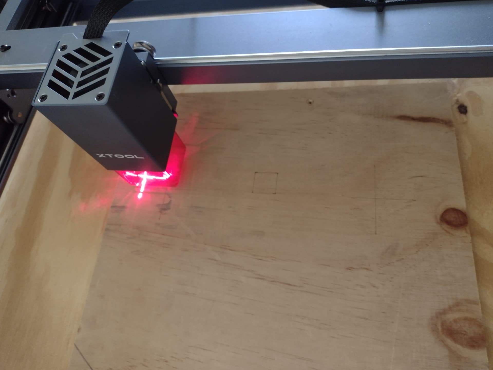
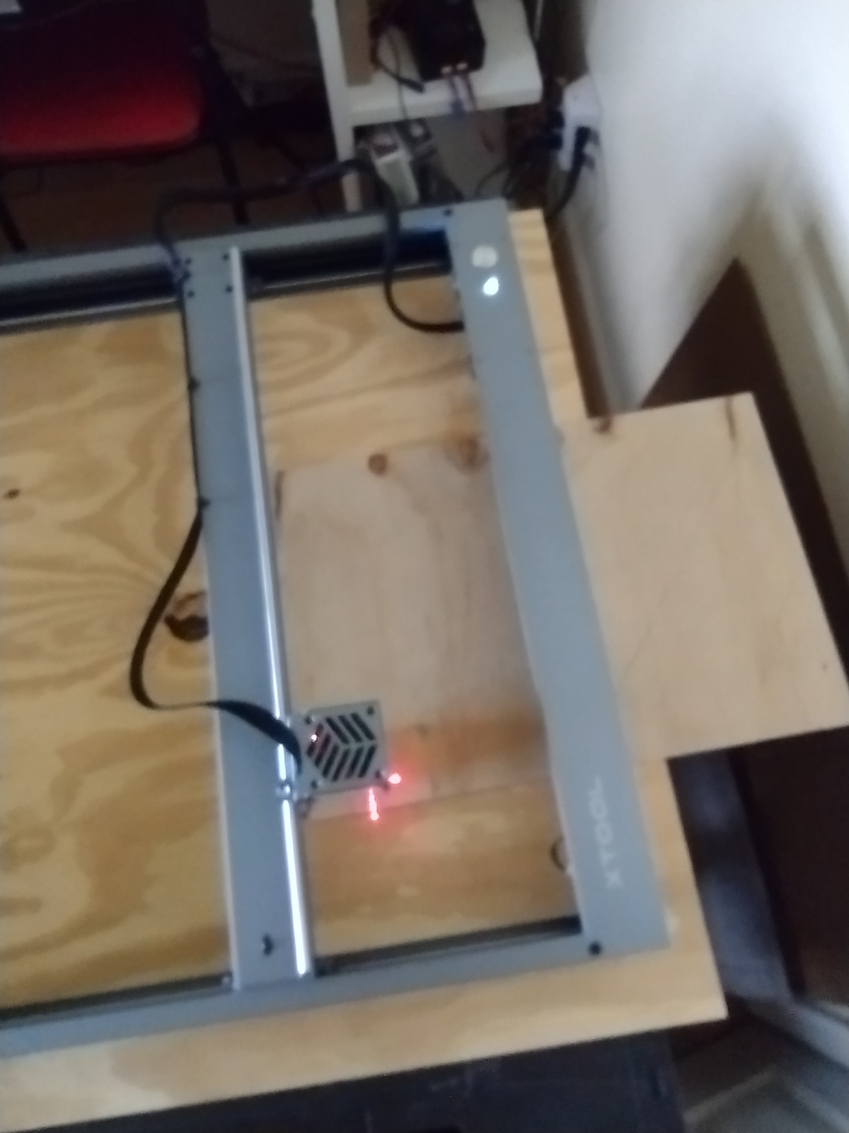
Test preparation shows the starting point of the job.
I open Top test and locate the board to be used in the machine. Top test marks are located towards the front of the machine.
Now, I send the laser to Home to have a reference point.
Following, I select the whole graphic and run Frame, to be sure the board is in the correct position.
Following, I run the cut/engrave.
I send the laser back to Home.
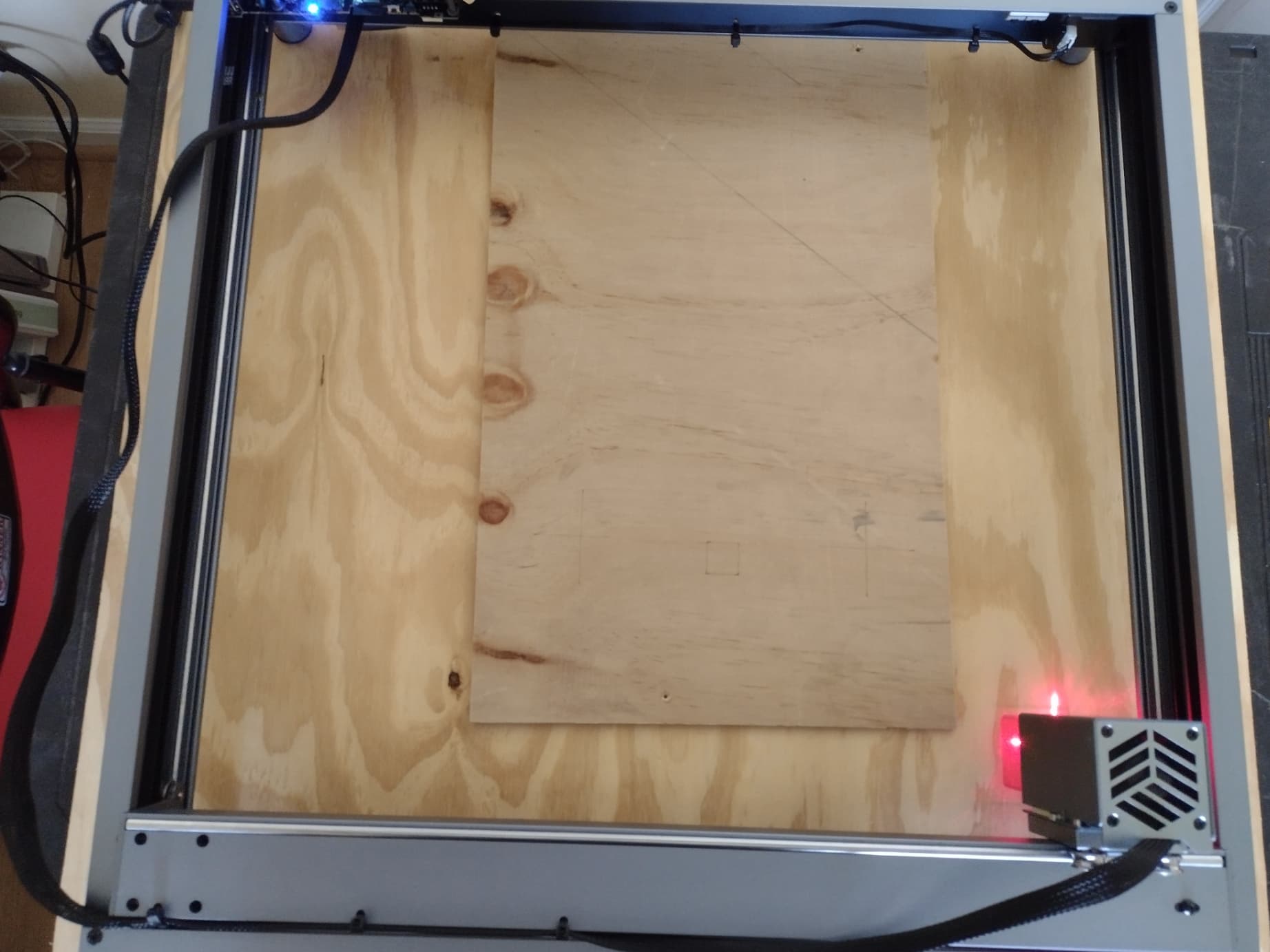
I open a new project in LB bringing Bottom Test to the screen.
The bottom test is located towards to back of the machine. Therefore, I move the board towards the back of the machine.
I select the drawing and run the frame again to confirm the board is in the correct place.
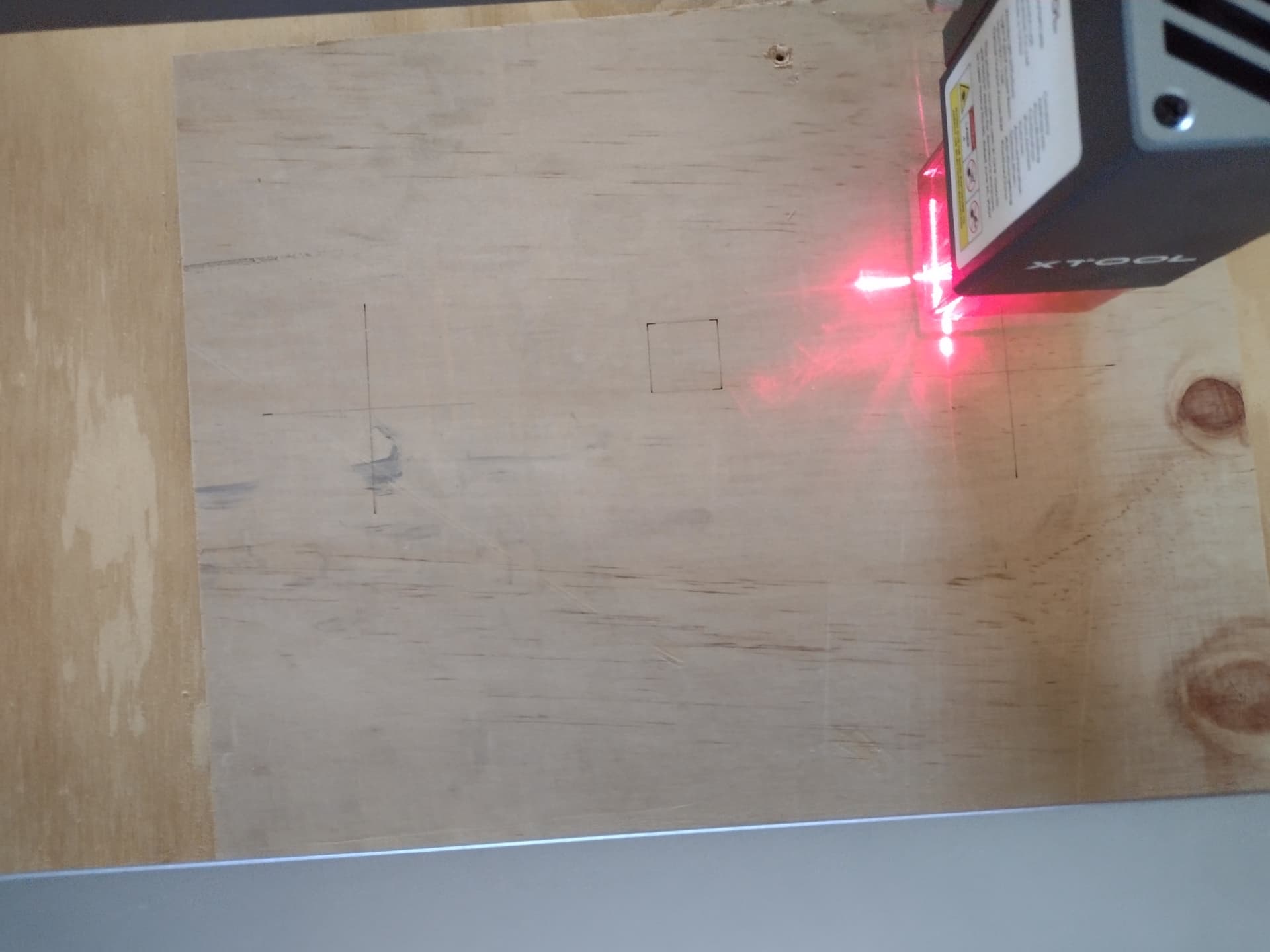
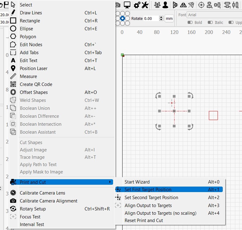
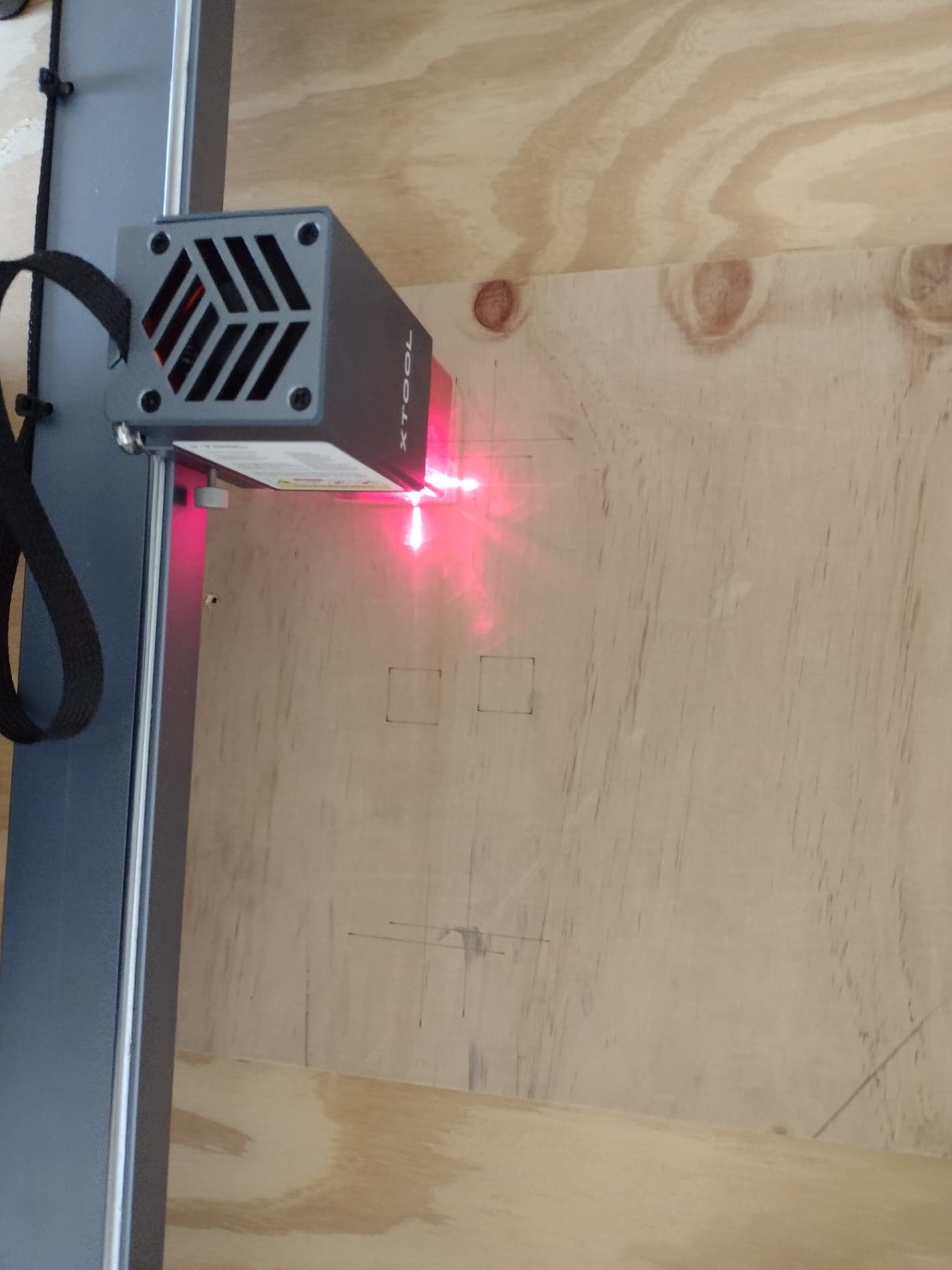
Now, I jog the laser to the first target.
I select the cross-hair and select the first target in LB.
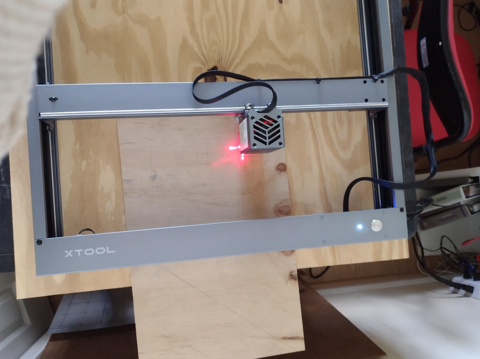
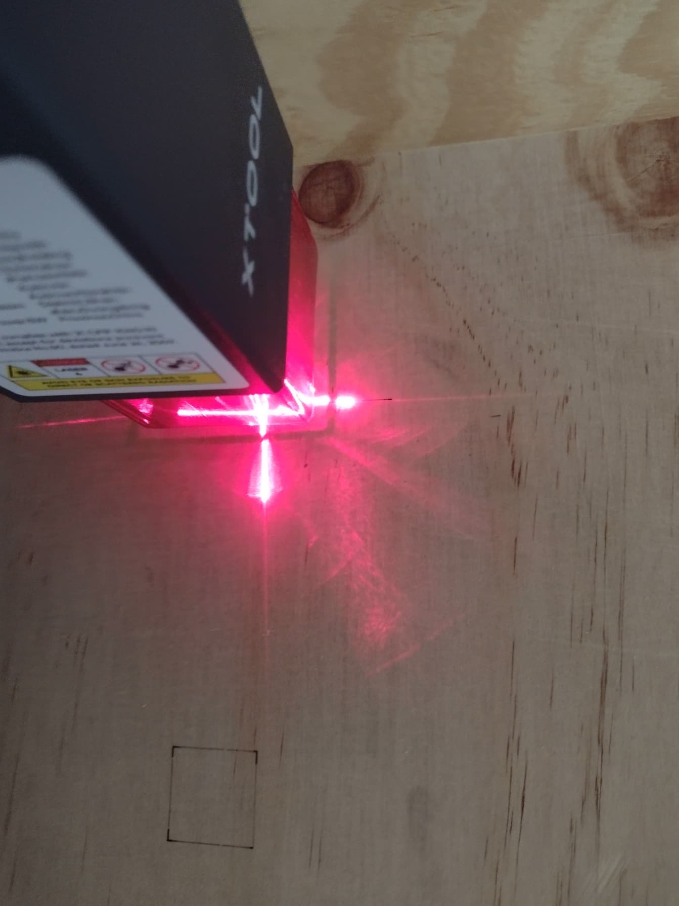
Following I jog the laser to the second target.
I select the second target in LB and set the second target.
Now, I select the whole graphic and Run
Follows first 5 files.
Test preparation.lbrn2 (7.8 KB)

Sorry, I see the pictures are all messed up. Let me know if you want me to re-order them or produce something better in any way.
Thanks for the detailed responses… Before I try to parse those too much I think I’ve seen a problem. Let’s see if this fixes it before moving forward.
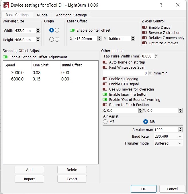
In Device Settings you have Laser Offset “Enable pointer offset” enabled. Can you disable that and zero it out for good measure?
After disabling, can you try your test again? From my initial review there was nothing fundamentally wrong in the approach. Some unnecessary steps but nothing fundamentally wrong.
I do wonder how you’re homing though since I didn’t think D1 had homing switches.
You have a point. xTool does not have homing switches. When I “home” from LB the laser goes to 0,0.
That may be the problem. Why besides performing the test you suggested I do the process for “machines without homing switches”. The problem I have with that is that I read the process but I didn;t understand it. Can you give me a fool-proof steps to try that one?
This isn’t a problem as long as you’re going to your machine 0,0. I assume you’re starting the machine from the expected 0,0 position.
Did you disable “Enable pointer offset” in Device Settings? I’m almost certain that’s the cause of the issue.
Not yet. Give me a few minutes, please. I am not at home right now. However, keep in mind that the laser crosshair is shifted in one direction and the result has a shift in both directions, plus, I tried before twice the bottom test without moving the board, and the shifted result was different each time. Anyways, I will try your approach today.
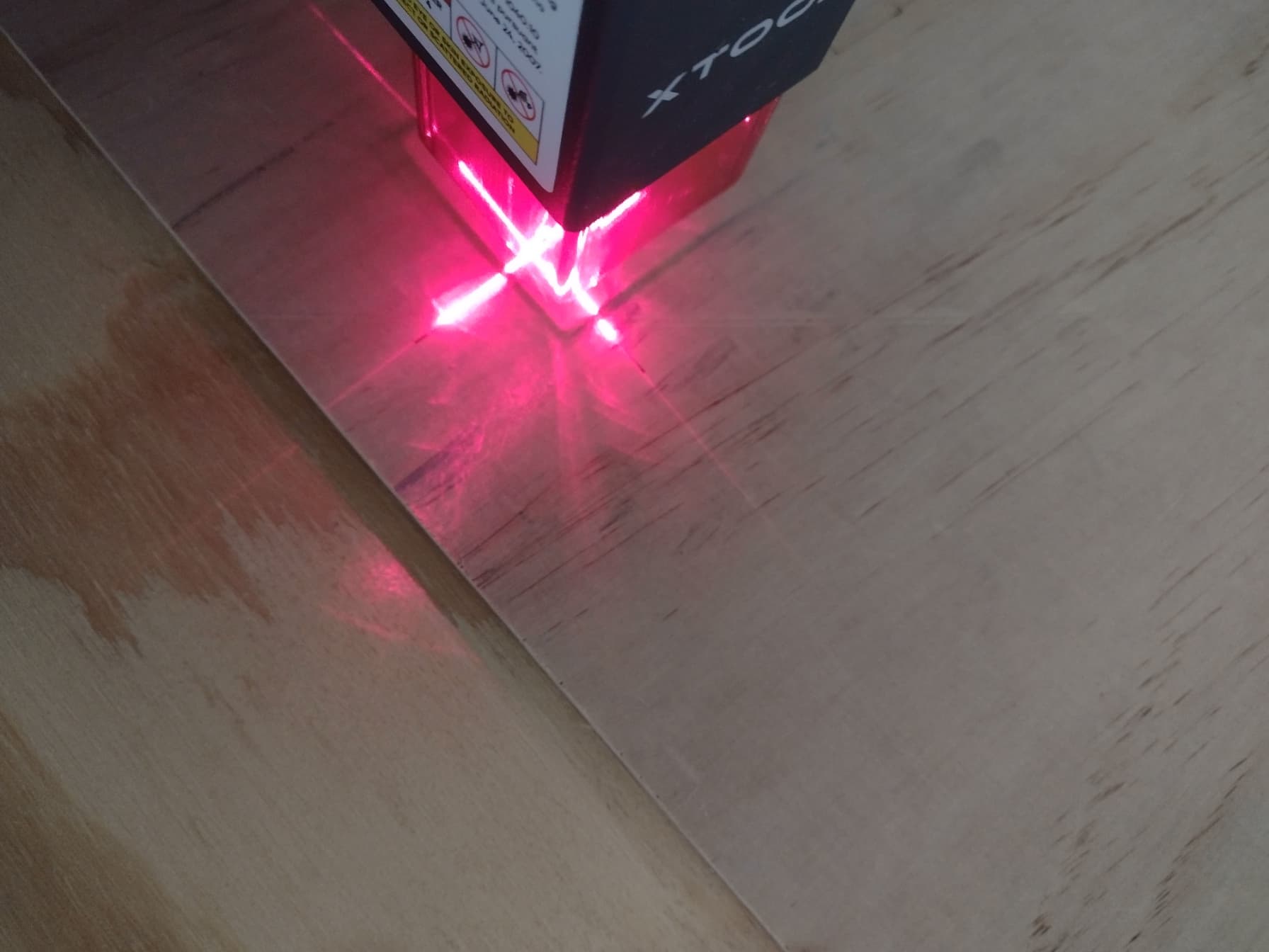
I disabled the pointer offset but there was no news. However, I made marks in the base board to reference where the crosshair was in the run. Then, I moved the board, set again new start and end targets, and run again. As I thought, the new targets fall right where the marks from the previous run were. The circles are the referenced marks. Where the ruler is is the second run, and next to it is the first run from where I draw the reference into the baseboard. The ruler is facing the right side of the unit. (rotate the picture 90 degrees clockwise). The way I see this is that the unit is ignoring the first and second target positions.

I missed something in your workflow the first time reading through but your last post made me revisit it.
I think you’re missing a step. After you set your second target, are you issuing an “Align Output to Targets”? You can use either version in this case. No scaling version is probably more appropriate in this case since no scaling is required.
Try adding that after setting your second target. If you use the wizard it steps through this.