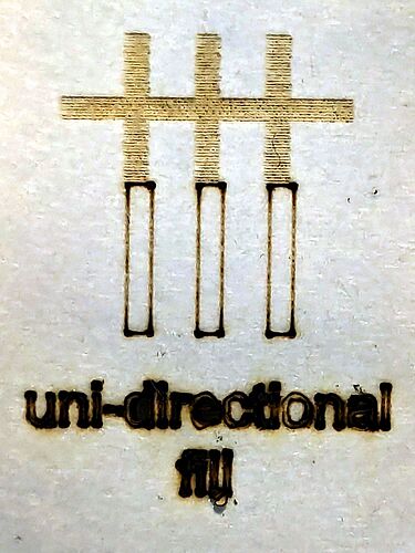
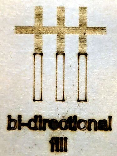
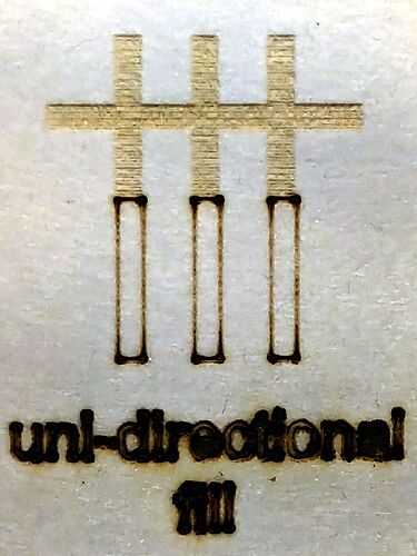
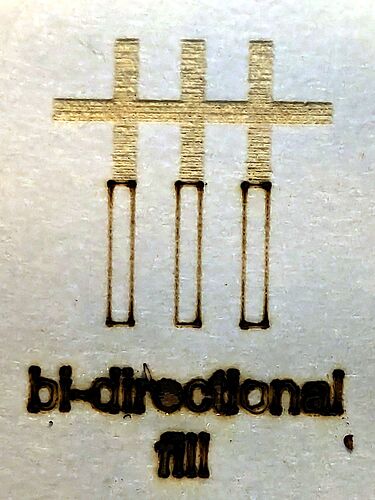
Cannot align bi-direction and non-bi-directional fills at the same time

I am able to use Scanning Offset Adjustment | Line Shift to make bi-directional fills perfect, both in terms of alternate line alignment and also alignment with other work (like lines). Alternatively, I can use Scanning Offset Adjustment | Initial Offset to make non-bi-directional fills aligned with other work (like lines). However, there is no combination of Scanning Offset Adjustments that will work for both at the same time (having a layer with bi-directional fill and a layer with non-bi-directional fill, all looking correct and aligned with other works like lines). If I have values for both Line Shift and Initial Offset then bi-directional fills are not aligned with other work; if I have only Line Shift then non-bi-directional fills are not positioned correctly, and if I have only Initial Offset then bi-directional fills are of course not correct.

Am I missing something, or is this a bug? In searching the forum, I found this from 5 years ago which seems related: Scanning offset adjustment seeming to not apply when bi-directional fill is off

OMTech AF2028-60 / Ruida KT332N DSP:23.01.14 / Lightburn 1.6.03

This may be another machine with the wrong STEP signal polarity for either (or both!) axes from the factory. Some earlier problems explain whatā€™s going on:

If getting the polarity right doesnā€™t fix it, then things get interesting. Successfully running a backlash test pattern will eliminate a bunch of other possibilities:

Scale this test pattern to fit the platform and run it as fast as it will go in Line mode with optimizations turned off and power set to mark cardboard:

GrundTest.lbrn2

Any distortion in the results on the cardboard indicates a mechanical problem, which I donā€™t expect ā€¦

Well hello Ed! I hope your plotter is still working nicely. I recall we both have the same model OMTech laser, by coincidence (or is it?).

I already had the PWM Rising Edge issue which took a while to solve. Iā€™d assumed it was too much acceleration or something but even with those set very low it still happened. Then after much googling I found the P.R.E. issue and when I changed ours, it worked great. Now I try to post about it whenever someone has issues that look like missed steps. Itā€™s the second most common post I do, the first is telling people they need to calibrate scan offset before using bi-directional fills. I asked Lightburn to add a dialog box when bi-dir is enabled for the first time for a user, but they declined, and it remains one of the most common issues.

This is something else, and feels a lot like a Lightburn bug.

If adding photos with settings and results would help, I can make those.

I knew there couldnā€™t be two of you! :grin:

We moved earlier this year and ā€¦ well, the plotters & supplies are unpacked on a conspicuous shelf, so thatā€™s a start.

Agreed.

A similar case:

We didnā€™t find a solution, but the thrashing around may suggest a test or approach you havenā€™t yet tried.

It feels like an HV supply timing problem, but the fact that it isnā€™t handled by the timing variables LightBurn provides is worrisome. I donā€™t have a good model for what else it could be.

I did the GrundTest and itā€™s perfect. This does not appear to be a missed-step issue.

Iā€™m attaching a Lightburn file. How does it engrave for you?
Scanning Offset Test.lbrn2 (40.5 KB)

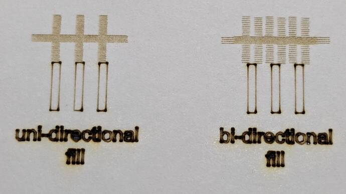
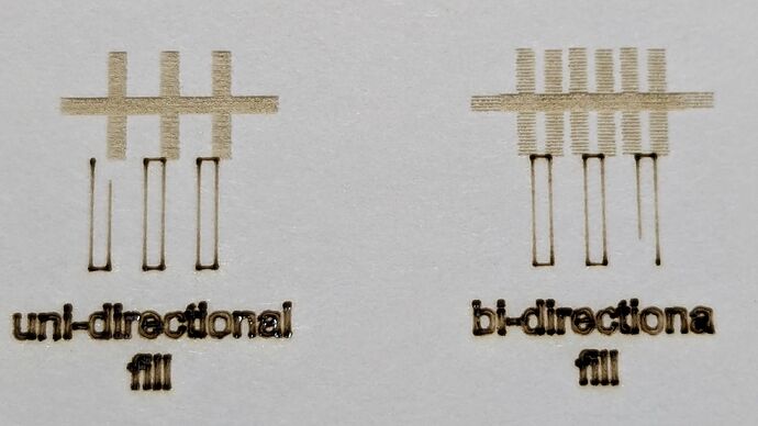
Here is how it engraves for me, with Scan Offset settings used for each of the 3 tests. I know you like to science things out! I should have included a picture in my first post.

Pretty much OK. :slightly_smiling_face:

This is with 1.7 RC-11, not that I think it makes any difference here, and after rebuilding the Scanning Offset Table from 50 mm/s to 500 mm/s to ensure I wasnā€™t working with old cruft. I reduced the power levels in your file to not quite incinerate white cardboard at the same speeds. The photos had their contrast blown out to make the lines more visible.

The uni-directional pattern is maybe 0.1 mm to the left of where it should be:

The bi-directional pattern is dead on:

Then, because Iā€™ve never done it before, I filled in 0.1 for all the Initial Offset values in the table.

The uni-directional pattern now seems better aligned:

The bi-directional pattern also skootches 0.1 mm to the right:

So the Initial Offset value does what I thought it did.

So my uni- and bi-directional patterns show the same type of misalignment yours do, but to a much smaller extent.

The HV power supply specs, such as they are, always seem to mention a 1 ms rise time / response time / whatever, without any further details. At the 500 mm/s pace of those engravings, 0.1 mm is only 200 Āµs, so I think weā€™re looking at tiny differences in the very leading edge of the rise time + tube firing delay: your machine is slightly slower than mine, for no good reason.

I could make a case for separate Initial Offset values applied to uni- and bi-directional scanning modes, although itā€™s unclear to me how (or if) that should vary with the scanning speed.

For whatever itā€™s worth, the Scanning Offset table:

mm/s    mm
 50    0.000
100    0.050
200    0.075
300    0.100
400    0.150
500    0.200

I donā€™t believe more than one significant figure, either, but those are half the distances seen in my measuring magnifier. :grin:

It seems you have the identical issue, but as you said, to a lesser extent since your needed offset times are smaller. Small enough I think you could split the different and have half the error on each in case you use both (or, if you only use bi-dir then optimize for that).

My value for 500 mm/s is 0.55 so nearly 3x yours, hence my outcome is that much worse. If I optimize for halfway, each are 0.5 mm off, which is more than Iā€™m will to live with. Iā€™m going to try to log an issue with Lightburn to see if they can address it somehow. Perhaps separate Initial Offset for uni- vs. bi-direction scanning like you suggested (although my bi-dir offset is 0; does it ever need to be anything but? If not, then ā€œdonā€™t apply I.O. to bi-dirā€ would be the fix, or, if they are only ever the same value, do away with one of the columns and just use the single value correctly for each type).

Iā€™m afraid I donā€™t know anything about the HV side of things.

Itā€™s all Iā€™ve ever known: life is too short for uni-directional scanning.

:grin:

That says the line-to-line offset is over a millimeter = the delay is over 2 ms = the power supply is sloooowww compared to ā€œwhat it should beā€ according to the minimal specs.

Not, of course, any way you could use the timing to support a warranty claim, but it definitely points toward a hardware spec problem, rather than a software issue.

Which, equally of course, could be ā€œfixed in softwareā€ if the delay remained constant, but ā€¦ yick.

Sometimes I need things to be Very Pretty, so you can image my dismay when the pretty part was shifted compared to everything else!

I might know what this could be. If you have RDWorksV8 try opening and running this file: RDWorksTest.rld.txt (595.5 KB) (rename to remove the .txt at the end)

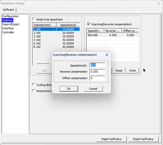
Set 'Offset compensation to 0, and only enter the reverse scanning amount:

You might need to enter -0.555 if 0.555 compensates the wrong way.

If you get a perfect result for both uni and bi directional with this test let us know.

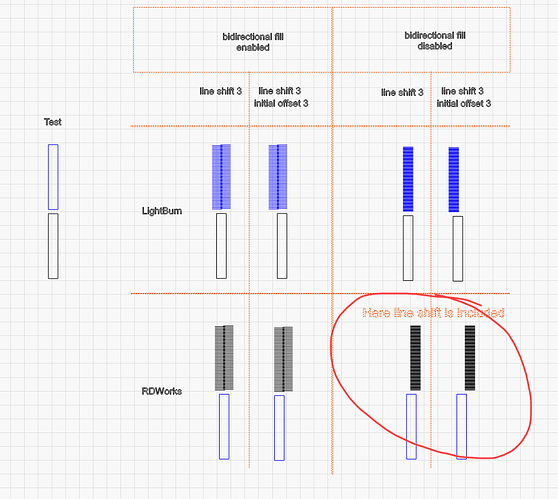
I looks to me that with RDWorksV8 the reverse compensation (equivalent to a line shift) is being applied also to the ā€˜x-unilateralā€™ (non bi-directional) fill, which LightBurn does not seem to do (at least not in this version), but if we did - then that should correct the issue youā€™re seeing.

To visualise this, I have imported into LightBurn the .rd files from LightBurn 1.6.03 and RDWorksV8 8.01.62 for comparison. I havenā€™t got around to physically testing this yet, but it would be good to test at a few different controllers to be sure this is something that needs to change.

If you can install RDWorksV8 (free) and test this that would be great, if you donā€™t have a spare PC handy perhaps @ednisley can test?

After a bit of thrashing around getting RDWorks set up ā€¦

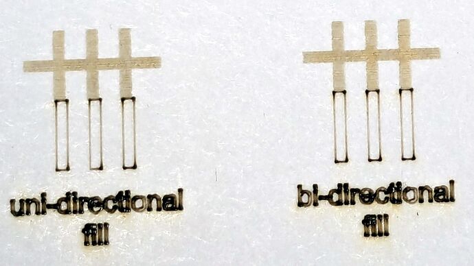
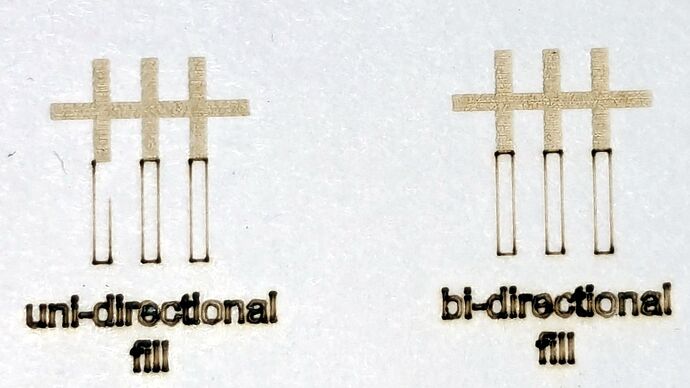
The engraved patterns run at 500 mm/s & 20% power.
The lines & letters run at 100 mm/s & 8-9%.
All on white cardboard, with image contrast blown out.

Scanning offset = 0.2 mm = the usual setting for my machine

In LightBurn:

In RDWorks:

The slight shift to the left in the LightBurn results shows LB does not shift the uni-directional pattern to line up with the vector shape, which is what started this entire thread.

Scanning offset = 1.0 mm to accentuate the difference

The uni-directional engraved pattern is still in the same slightly shifted position relative to the vectors:

RDWorks definitely applies the setting in both modes:

So applying the same offset value for both uni- and bi-directional engravings would fix the (slight) offset in my machine. I think it will also fix the misalignment in @Dithermasterā€™s machine.

Being me, of course, makes me want a different offset value applied to the uni-directional case, just for fine tuning. Which would require a duplicate offset-per-speed table and that looks like a UX disaster cominā€™ on strong.

Excellent, thanks Ed!

Your results help a lot.

Actually I have noticed that the start-stop points on a single direction fill can be offset slightly due to tube dynamics e.g.I think here in the forum somebody had to replace a CO2 tube because at lower power it exhibited a delayed start which was somewhat hidden on bidirectional fill since every other line helps to square up the edge. So I can image a scenario for this kind of additional control, but as you say - no need to clutter the UX more than needed since we are already in edge-case territory.

Cheers, will take these findings to the powers that be :slight_smile:

Thanks Ed for your RDWorks testing. Iā€™m primarily Mac and would have had to dust off and connect a PC to do that test.

Thanks Nicholas for your continued attention to this issue, and I hope the software team can come up with a solution!

1 Like

We donā€™t see a lot of people mixing Unidirectional and Bidirectional fills, and Iā€™m honestly not sure I understand the reason for needing this, but Iā€™ve updated the code to apply the line shift to to uni-directional fills as well.

That will appear in 1.8.

Thank you, I look forward to the fix.

Itā€™s not only about mixing - if you have one project that uses bidirectional and another that uses unidirectional, only one will engrave correctly.

ā€œMixingā€ = someone who uses both. In general, if bidir works, you use that, because itā€™s significantly faster.