Greetings All, As I’m new to the laser world I was hoping someone might be able to help me with some directions.
I have an Ender 3 Pro with a 4.2.7 Mother Board 32 bit and 512 ram. It is running Miguel Risco-Castillo’s firmware. I have installed a Sovol 5 watt laser that is using PWM control for the laser. I have installed LightBurn 1.3.01 software and am still learning my way around using it.
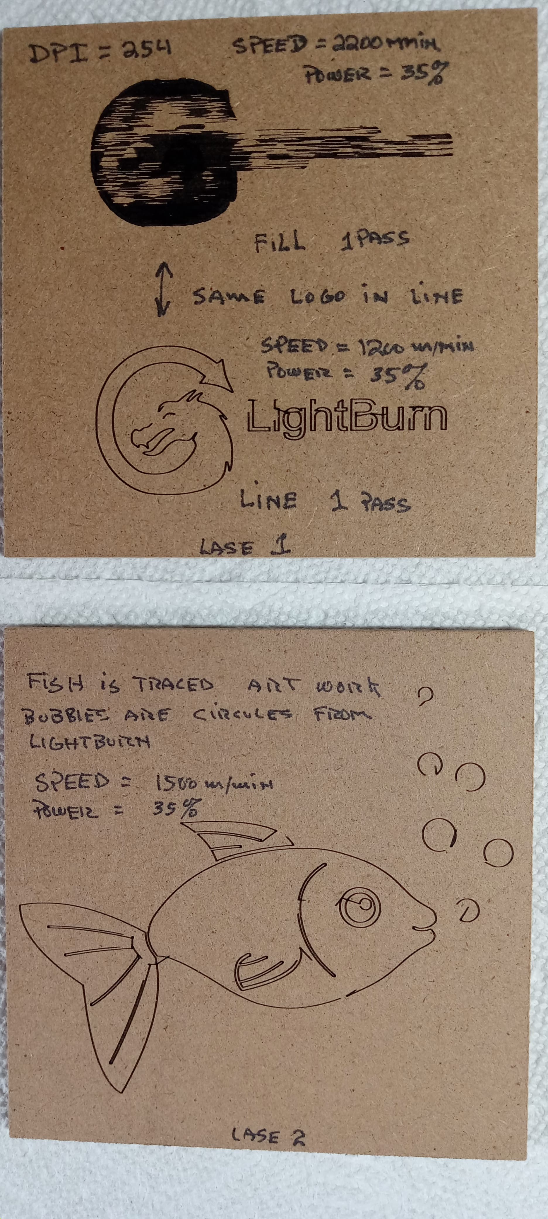
I have attached a couple of pictures of the’ " Printing, Burning or lasering " results and was hoping that I might get some help with their results. Thanks for any and all view anyone might have.
Regards Doug
![]()
What happens if you dramatically slow down the engraving? It’s possible you’re dealing with low PWM frequency.
What pin header is the laser connected to? Do you know the PWM frequency for that header?
Slowing down the engravings will cause a much deeper engraving with some burning. If I lower the power below 30% there will be a lot of skipping in the lines. Doing that in the raster scanning produces similar results. If you have some thoughts on setting please advise me and I will set up tests.
The Solvo laser has it’s main power ( 24vdc ) supplied directly from the 4.2.7 mother board via the main buss. The PWM signal is derived from the parts cooling fan circuit it is a "o = off to 255 = max on. This pulse width is used for cooling fan rpm the larger the number the higher the fan RPM and frequency. Since the PWM input to the Solvo is 0 to 5 vdc I have picked off the mosfet gate signal through a 100 ohm resistor ( current limit ) to drive the laser.
I could measure the frequency of the drive signal for a set of power settings if that would help. Is there a lower drive frequency for the PWM signal? It may be that I need to run at a higher power value and increase the speed to adjust the burn?
The X and Y axis have velocity values of 300 and acc/dec of 500 although I’m not sure of what they represent in the firmware.
Thank you
D
Further reviews of the topics under Creality pointed to a laser frequency of 1K hz. I will try to find the power setting 0 to 255 that gives that frequency and then work with the speed.
D
You may be misunderstanding the relationship of PWM frequency to power. The frequency itself does not determine power. Duty cycle of PWM determines power. So 100% duty cycle is equal to full power and 0% duty cycle is equal to no power. PWM frequency would affect the potential latency of response.
What I was speculating was that the laser was turning on/off with delayed response which is why the engraving lines didn’t line up. This is very typical of Marlin based lasers.
Fan control PWM generally has very low frequency settings because there’s usually no need for very fast fan response. 1000Hz is typically the minimum frequency you’d want for a laser. Fan PWMs are often in the 10s of Hz range so see if you can identify what yours is specifically.
PWM frequency and voltage testing showed that at any setting for the fan circuit the frequency was 7.87 Hz. The set point to voltage range was 0 = 0vdc, 1 = 0.987vdc, 127 = 2.83vdc, 253 = 4.89vdc all at 7.87hz. Set points 254 & 255 = 4.93vdc at 0.0Hz.
Would it be safe to say that the Ender 3 xxx with the 4.2.7 mother board will not make for a good laser setup?
Thank you for clarifying the PWM Hz to Power relationship. I was way off base in my thinking. The scope this morning, as seen from the above data, is quite clear.
Is there a circuit that could multiply the 7.87hz up to a usable range? 1000 hz maybe ?
D
Possibly. I’m not familiar with the specifics of the board. Are you able to change the frequency through configuration? In any case 7.87hz is far too low to be useful for laser engraving.
The problem is not in the frequency itself. It’s in the resolution of control. So just scaling the frequency is not enough if the control resolution isn’t also increased.
By the way, I’m only speculating this is the issue based on a single bad image.
Try running a test:
- Create a square or tall rectangle in LightBurn
- Modify the layer to have 2 sublayers. Sublayer 1 will be line. Sublayer 2 will be fill with these parameters: line interval set to 1 mm, bidirectional
- Set power and speed settings as you are currently doing for line and fill
- Run the burn
Examine the burn. If the engraving doesn’t perfectly fit within the shape then you may have an issue. If each engraving line starts past the first edge of the square and ends after the square then this is most likely a latency issue due to PWM frequency as speculated.
I will set up the test and post the results a bit later. Thank you again.
D
Greetings,
Here is the picture of the burn results. I did lower the power to 25% at a speed 1200 m/min.
Doc’
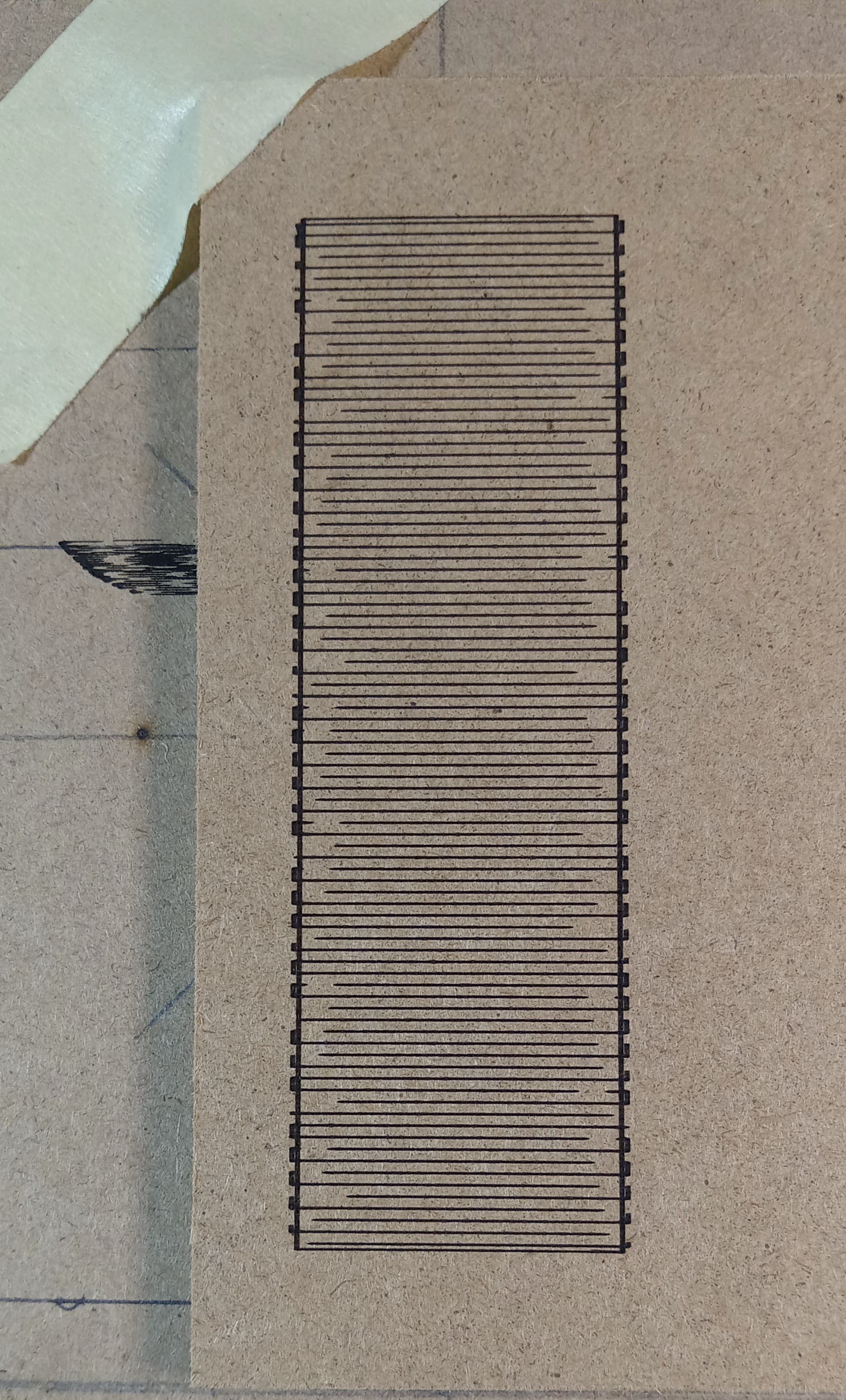
I assume from the picture that the engraving started at the bottom going left to right and then up from there based on the picture. This does look like exactly like what I would expect from low PWM frequency. Notice how the beam starts lates, and then stays on too long.
I’d suggest exploring if there’s a different pin header with higher frequency you can use or if you can modify the pwm frequency of the current pin through configuration.
Alternatively, you could just try moving very slowing as that will mitigate the impact of the response delay.
Yes the burn started at the bottom then left to right and up. I will see if the firmware in one of the configuration files has an edit for the frequency. A re-compile might be the ticket.
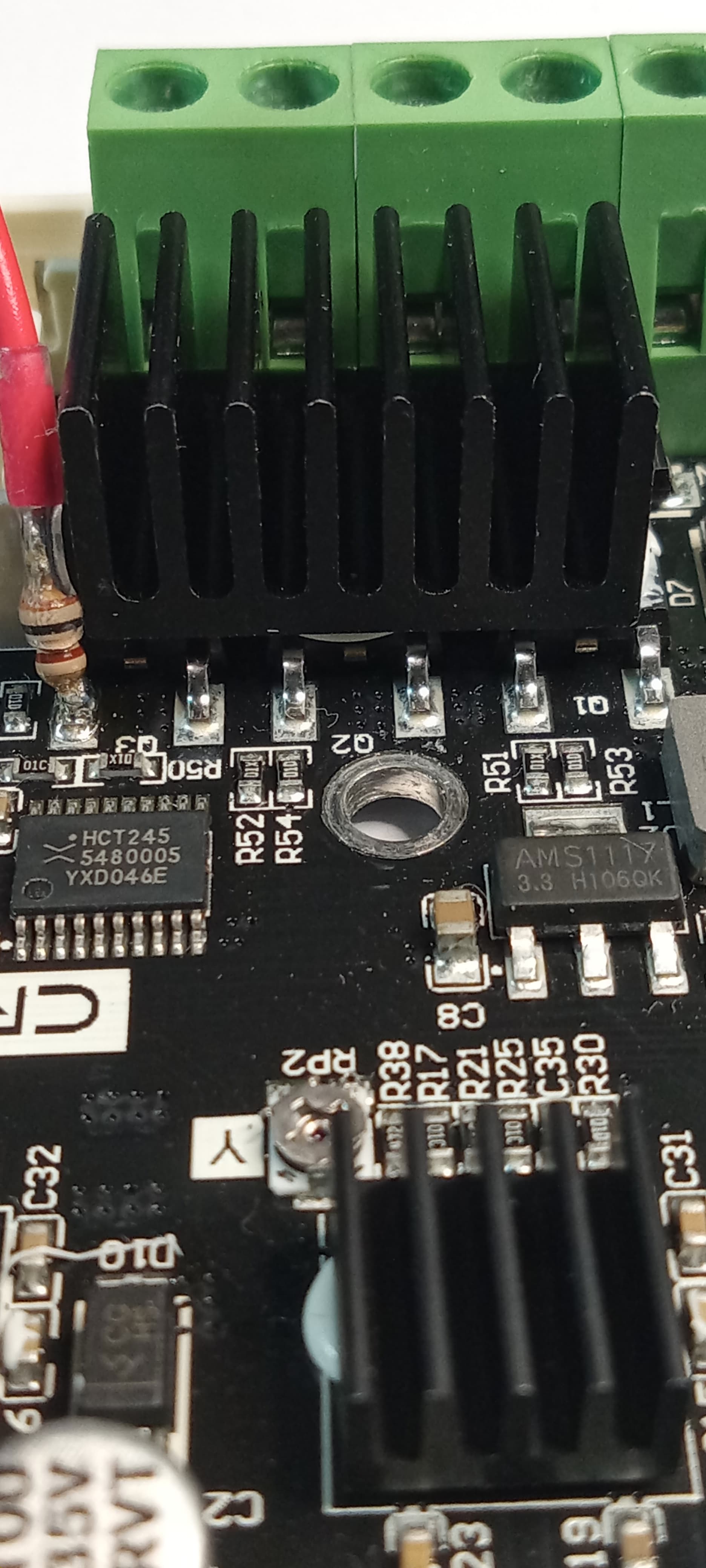
I have included a picture of the 100 ohm connection for my PWM take off point. This is the positive side of the cable and the negative side is any of the 24Vdc negative connections. I used the negative side of the of the main cooling fan for the hot end. This picture is for my 4.2.2 board but the 4.2.7 is the same pin although the 4.2.7 board at this location looks a little different from the 4.2.2 but it works just the same. The 100 ohm resistor is a MUST.
I’m going to try to fine some slower moves and power settings in the short term to see how the printer reacts.
Thank you again for your time and directions and helping me with my laser education.
Regards
Doc’

Are you saying the pin header is designed for 24V PWM? The laser module is likely setup for 3.3V or 5V logic. It may be tolerant to higher voltages but 24V is rare.
Are you using the resistor to reduce voltage?
Are there no pins that will provide TTL PWM on the board?
The pin header or fan plug is for the MosFet output to the cooling fan which is 24vdc. The point that I picked off is the gate voltage signal to the MosFet which is 1 to 5 Volt. The 100 ohm is a current limit resistor so that the drive circuit producing the gate drive signal has a load to see.
The resistor is only a current limit.
I have not found any pins on the Creality 4.2.2 or 4.2.7 boards for a direct TTL / PWM signal.
Doc’
[quote=“berainlb, post:11, topic:89929”]
I’d suggest exploring if there’s a different pin header with higher frequency you can use or if you can modify the pwm frequency of the current pin through configuration.
[/quoI’d suggest exploring if there’s a different pin header with higher frequency you can use or if you can modify the pwm frequency of the current pin through configuration.te]
In an effort to change the PWM through configuration I have found my way to the Miguel’s current source code for this printer.
In the from the Marlin folder in the Configuration_adv.h file I have found the following information regarding the PWM frequency. But I am at a loss so far to understand how to edit it for a higher frequency.
Starting at my line # 594 FAST_PWM_FAN_FREQUENCY
-
Set this to your desired frequency.
-
For AVR, if left undefined this defaults to F = F_CPU/(22551)
-
i.e., F = 31.4kHz on 16MHz microcontrollers or F = 39.2kHz on 20MHz microcontrollers.
-
For non AVR, if left undefined this defaults to F = 1Khz.
-
This F value is only to protect the hardware from an absence of configuration
-
and not to complete it when users are not aware that the frequency must be
specifically set to support the target board. -
NOTE: Setting very low frequencies (< 10 Hz) may result in unexpected timer behavior.
-
Setting very high frequencies can damage your hardware.
-
USE_OCR2A_AS_TOP [undefined by default]
-
Boards that use TIMER2 for PWM have limitations resulting in only a few possible frequencies on TIMER2:
-
16MHz MCUs: [62.5kHz, 31.4kHz (default), 7.8kHz, 3.92kHz, 1.95kHz, 977Hz, 488Hz, 244Hz, 60Hz, 122Hz, 30Hz]
-
20MHz MCUs: [78.1kHz, 39.2kHz (default), 9.77kHz, 4.9kHz, 2.44kHz, 1.22kHz, 610Hz, 305Hz, 153Hz, 76Hz, 38Hz]
-
A greater range can be achieved by enabling USE_OCR2A_AS_TOP. But note that this option blocks the use of
-
PWM on pin OC2A. Only use this option if you don’t need PWM on 0C2A. (Check your schematic.)
-
USE_OCR2A_AS_TOP sacrifices duty cycle control resolution to achieve this broader range of frequencies.
*/
// Line 613
//#define FAST_PWM_FAN // Increase the fan PWM frequency. Removes the PWM noise but increases heating in the FET/Arduino
// Line 614
#if ENABLED(FAST_PWM_FAN)
//#define FAST_PWM_FAN_FREQUENCY 31400 // Define here to override the defaults below
//#define USE_OCR2A_AS_TOP
#ifndef FAST_PWM_FAN_FREQUENCY
#ifdef AVR
#define FAST_PWM_FAN_FREQUENCY ((F_CPU) / (2 * 255 * 1))
#else
#define FAST_PWM_FAN_FREQUENCY 1000U
#endif
#endif
#endif
// Line 625 end of PWM info
I’m trying to understand the infor after line 614 as it may be there that the frequency can be edited. Maybe?
Doc’
Seems to me you’re on the right track but I haven’t looked much at Marlin configuration so can’t advise you on specifics.
I looked briefly at some of Miguel’s firmware repositories and see that there’s also a spindle_laser.cpp that looks to be referencing some PWM definitions as well. Not sure how these files are related.
Thank you for looking into the configurations. Which configuration file did you see the spindle_laser.cpp in?
I’m also going to post this PWM Hz question to Miguel’s forum and see what he can advise and will post the response back here.
I must say that at this point in the adventure it is all great fun and a perfect way to advance one’s knowledge of the systems. The integration of the 3D printer and the laser is quite intriguing. Thank you again for helping me advance.
To all the other readers please comment, as we all can learn from the Forum, Cheers
Doc’
Not a configuration file. It’s the actual source file. Not certain this is the correct repo but check out this link:
Ender3V2S1/spindle_laser.cpp at 72b609366965ba83826b6124878193de20c3d664 · mriscoc/Ender3V2S1 · GitHub
Glad I’m able to help in some way. This is prompting me to further explore Marlin configuration as I have an overdue custom firmware to create.
Thank you for the info, Ah, I see your in Miguel’s house and I’m posting to him at the moment.
Here is the title of the post on his Discussions forum:
Ender 3 cooling fan PWM frequency editing #702
Doc’
Greetings, I’m still reviewing your link to the source file. Endeavor to Persevere. So close.
Doc’