Ooops,

This looks about the same as the last test, maybe slightly better.
Are you certain the PWM is working at 1KHz?
I’m noticing the tails and gaps in the text as well.
After I changed the firmware and flashed the MB I put a scope on the PWM cable at the laser and verified that the voltage ranged from .700mv at 1 KHz to 4.94 V at 1KHz for settings of 10 to 255 for the fan using the printer control. I was not so happy with the results.
I’m testing today with the scope on during a burn to verify the frequency so as not to be chasing the incorrect issue.
Doc’
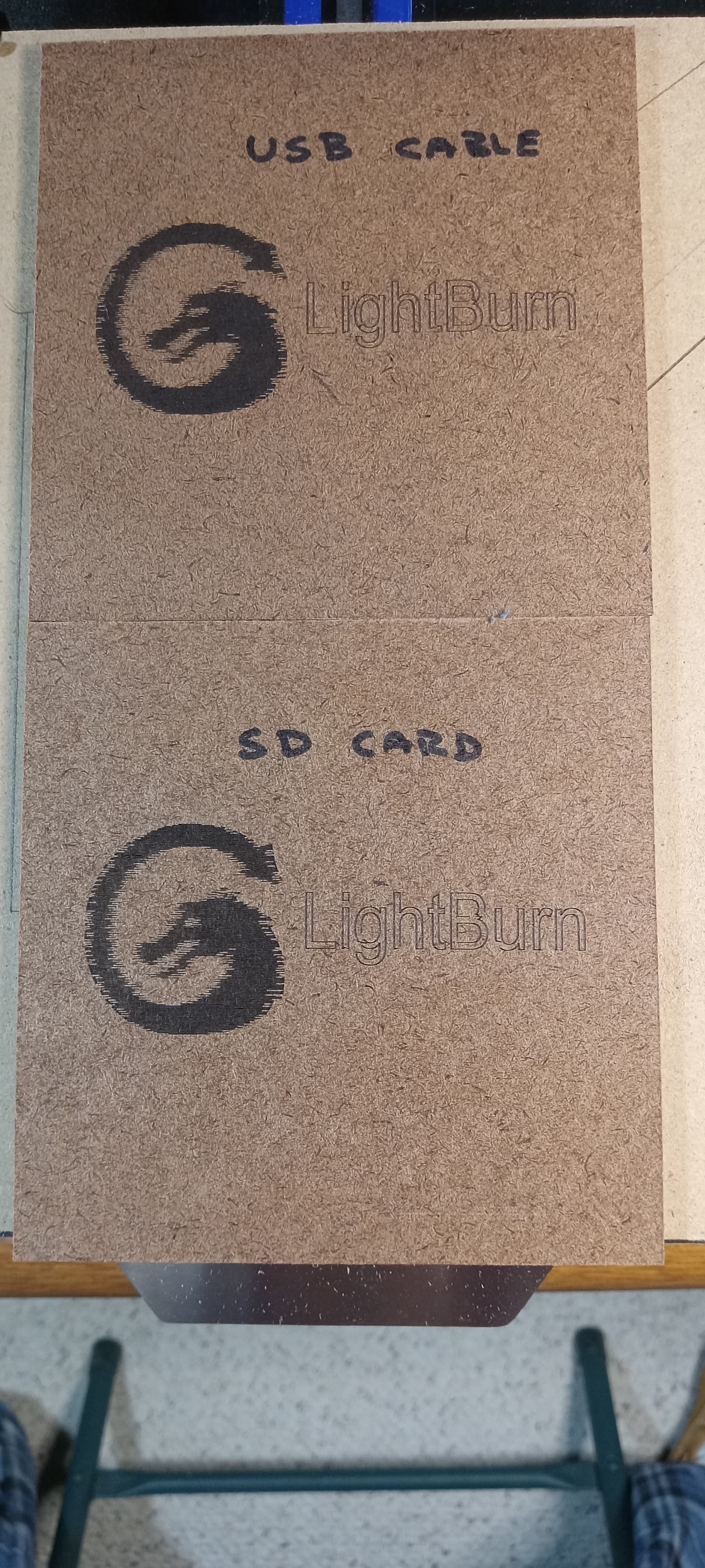
Here is the same file only run from an SD card to remove the USB connection as an issue. Oh well it was just a thought and the burn was about the same. Regarding the 1KHz I have noticed that the sound of the laser is a much higher pitch that when it was at 7.87 or 50 Hz. Just observing things.
I wonder if my flavor of Marlin / Miguels firmware is not the issue. Maybe some delay between the Laser command and the X / Y axis commands?
Mark posted a similar thought as I he did mention moving to a GRBL board based on a potential updating issue with speed. I’m not familiar with the difference between Marlin and GRBL. Any thought there? Maybe this is just a wasted effort, aside from the learning curve which is great.
Doc’
How are you measuring voltage? What you should be seeing is a square wave with voltage from 0 to 5V at 1KHz frequency. If this is RMS value then what you’re seeing is probably fine. But if it’s not and you’re seeing actual voltage changes then I wouldn’t expect that.
Some laser modules can take an analog signal but you would expect a consistent voltage with no associated frequency.
I’m wondering if the Marlin changes you made changed the frequency of the output but not the granularity of the control. Meaning the control granularity is still at 8.87 Hz although the output is higher.
GRBL is specifically designed for CNC motion control systems, has been updated with laser functionality, is fairly well standardized, and importantly, had a very competent base implementation using Arduino Uno and Nano. Laser control is well established with GRBL and performs well. Competent boards can be purchased very cheaply or with parts you may have around.
It may be a limitation of the hardware but uncertain. Does the Creality board use an Atmega 328p? If so, that would be the same MCU used in Uno/Nano so should be capable of generating a proper 1KHz PWM.
Sorry for the delay, The measurements are with a scope and a DVM set to read DC. The DVM is a Fluke 867B Graphical Multimeter which also displays the waveform.
Both meters show a variable dc voltage based on the value of the input riding on a 1 KHz square wave.
When I get back I’ll snap come pictures of the readings if you like.
The Processor on the 4.2.7 board is the ARM STM32F103RCT6 (512k).
Thanks again
Doc’
Do you have the input coupling set to AC, rather than DC?
If so, then the scope / DMM input coupling cap will set the 0 V baseline at the average value of the PWM input, which will cause the minimum and maximum values to “float” depending on the PWM percentage.
Set to DC, the lower voltage should be just over 0 V and the upper voltage should be just under 5 V, with the duty cycle varying according to the PWM value.
Greetings, I checked both meters and they are set to DC coupling. A great question thank you. The voltage range you mentioned are close to what I measured. The lower was 0.045 and the upper was 4.954 vdc. The pictures are the PWM signal during a burn. I have included several wave form pictures for viewing.
Thanks Again
Doc’


That looks just fine!
I misinterpreted “riding on an 1 kHz square wave” as having a baseline shift, which isn’t the case.
Bonus: nice meters!
Greetings, Sorry that at times I make up my own English language which comes across about as clear as mud.
Thank for the kind words regarding the metering. The Fluke is a 1993 vintage and the All-Sun EM1230 is a current one. I notice after these pictures that my probes might need a little cal to remove the leading and trailing spikes. Now where is that signal generator.
Thanks again for your thoughts regarding this little effort. I really believe that my current firmware is not 100 % regarding the laser operation. So for now I’m going to let this E3 Pro run a bunch of tests and maybe get or build a real laser as it was suggested and put the hot end a parts back together.
Thanks to everyone who went along for this ride and all of your help and comments.
My Best Regards
Doug
This topic was automatically closed 30 days after the last reply. New replies are no longer allowed.