Cuts not lining up - running out of things to try!

Hi there, I’ve got a new Chinese laser cutter and I’m going crazy trying to get cuts to align properly. I’ve attached a test file and hoping someone could try cutting it to see if you get the same results.

Here’s the history of my problem and what I’ve tried so far:

I discovered the problem cutting 6 identical puzzles. I copied and pasted the puzzle design to make copies inside Lightburn. 3 of them have places where the cuts don’t start and end at the same place while 3 of them are good. There is a different cut order in each of these puzzles even though they are individually grouped so a complete puzzle is cut before moving to the next. (A little more on that later).

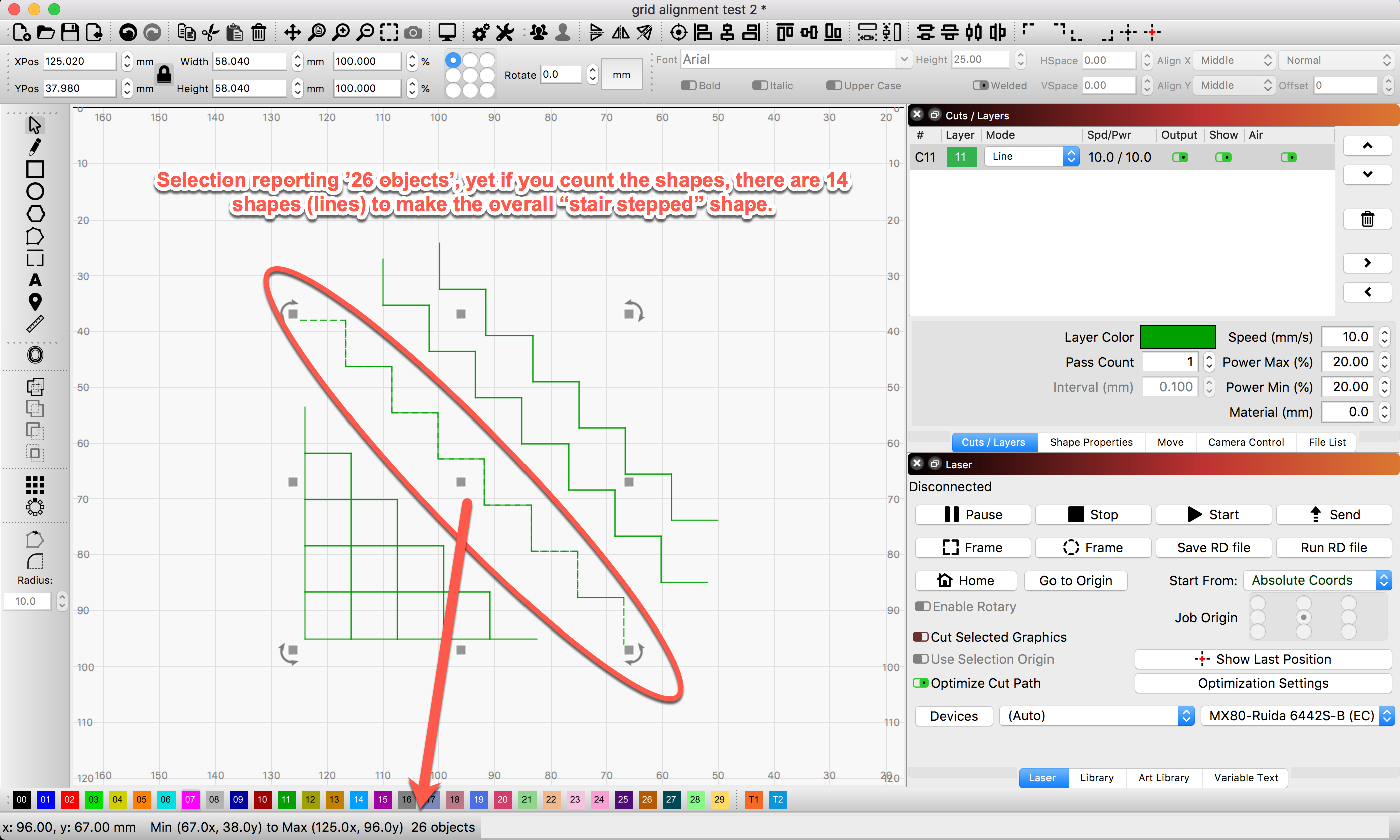
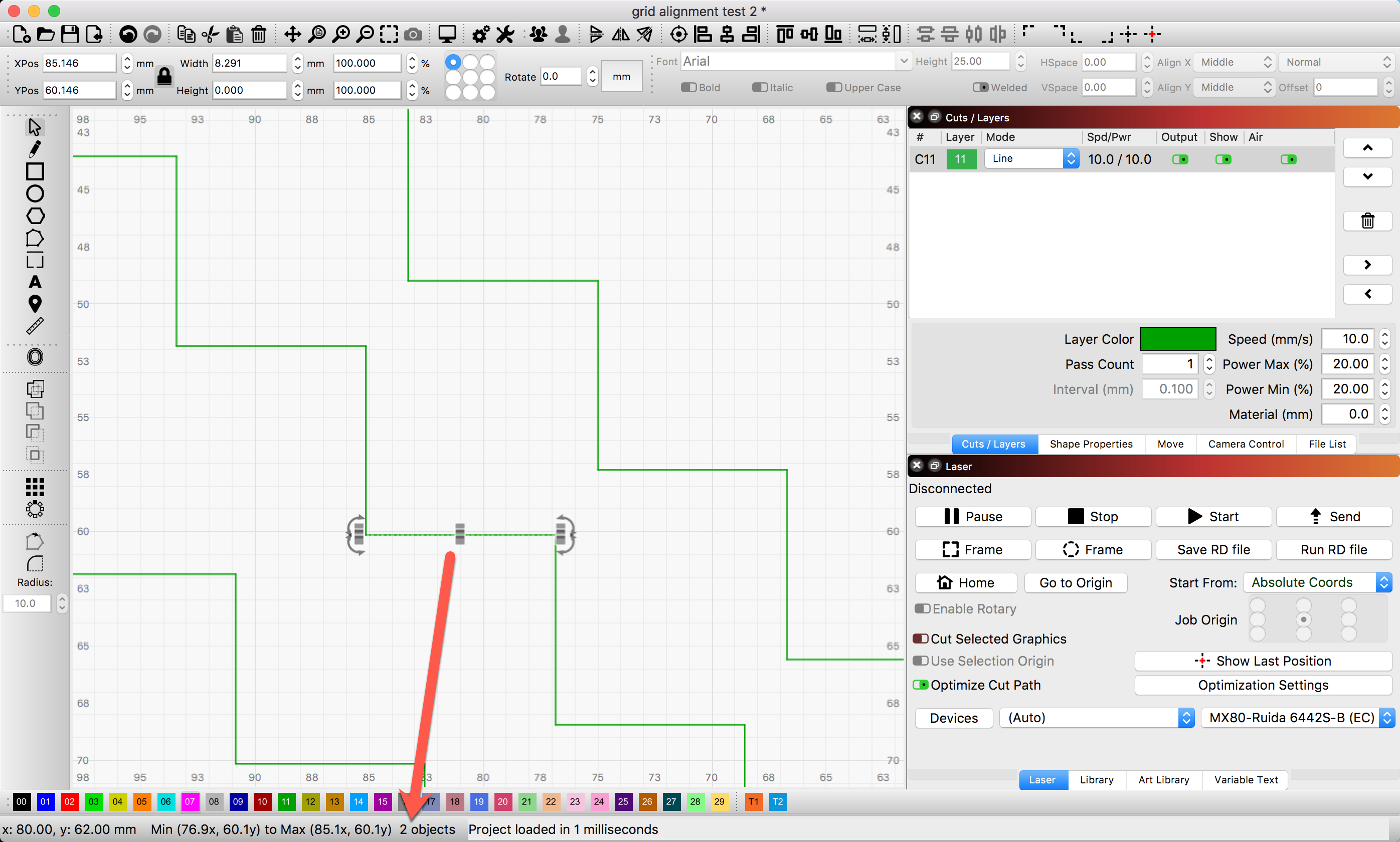
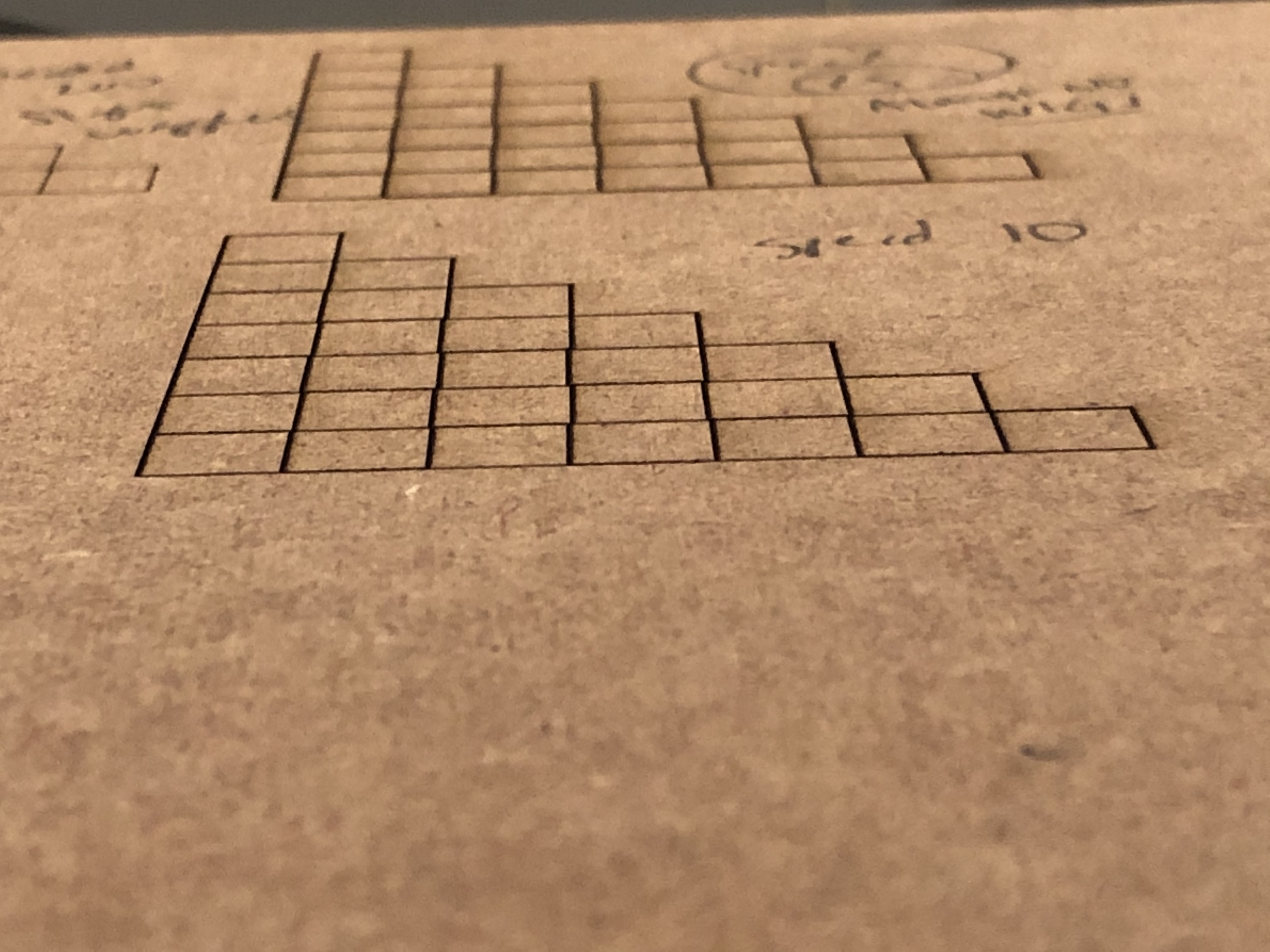
I’ve done extensive problem-solving using a different design with squares. I made this file so the head would change directions on every line segment in order to maximize errors. Of course I can cut this design perfectly if I cut all horizontal and then all vertical lines without breaking them, but the point is to get the cuts to align no matter what cut order. I figure if I can get this simple design to work then my other files will work.

Here’s the file:

grid alignment test 2.lbrn2 (28.2 KB)

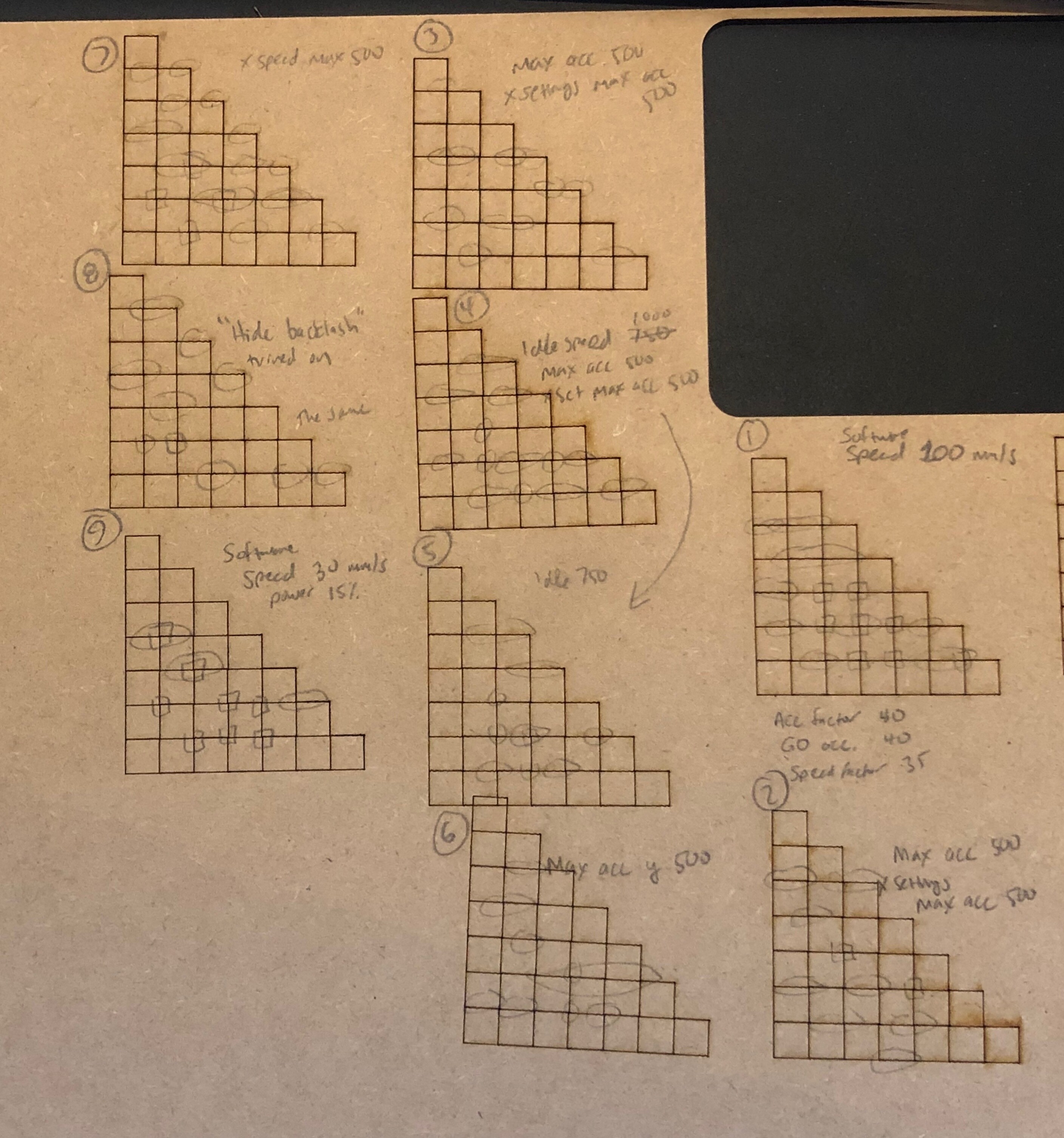
And here’s a bunch of trials with their settings:

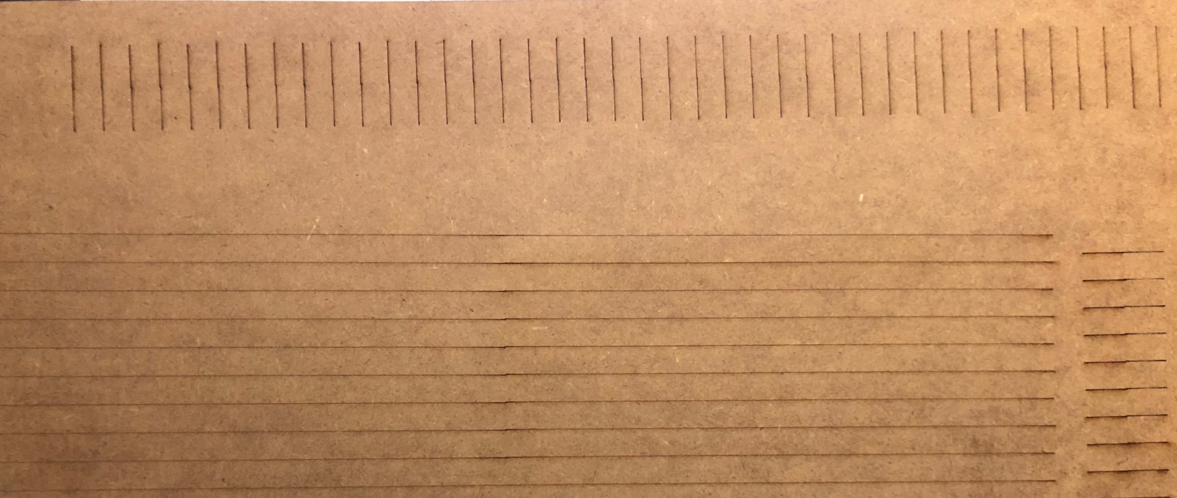
There are some wiggles that I found I can eliminate by reducing speed to about 20 mm/s. But the places where the cuts don’t align are killing me.

Changing idle speed, acceleration, rising edge (both on the Ruida 644XG and in the machine settings on LightBurn, both x and y) on and off, hide backlash on and off… nothing I’ve tried makes a difference. I have reduced acceleration down to 100 mm/s2 and cut at speed 10 mm/s so the laser head crawls slooooowly along, and the misalignment is exactly the same as if I have acceleration 1000 and speed 200.

The problem is 100% reproducible. The missed places are in the same places regardless of the settings and regardless of where on my laser bed the cut is made. I have checked the screws holding motors and belts and everything seems tight. I have examined the belt carefully for debris or damage to the teeth and it looks perfect.

If I change optimization settings to change the cut order, I get errors in different places. These are also reproducible within the same set of settings.

I have been in contact with the manufacturer, ZingCNCLaser, tried all of their suggestions as well. Today I got the response that if they make the file in CAD software and import to RDWorks, they get errors but not if they make it in RDWorks. Here’s their picture:

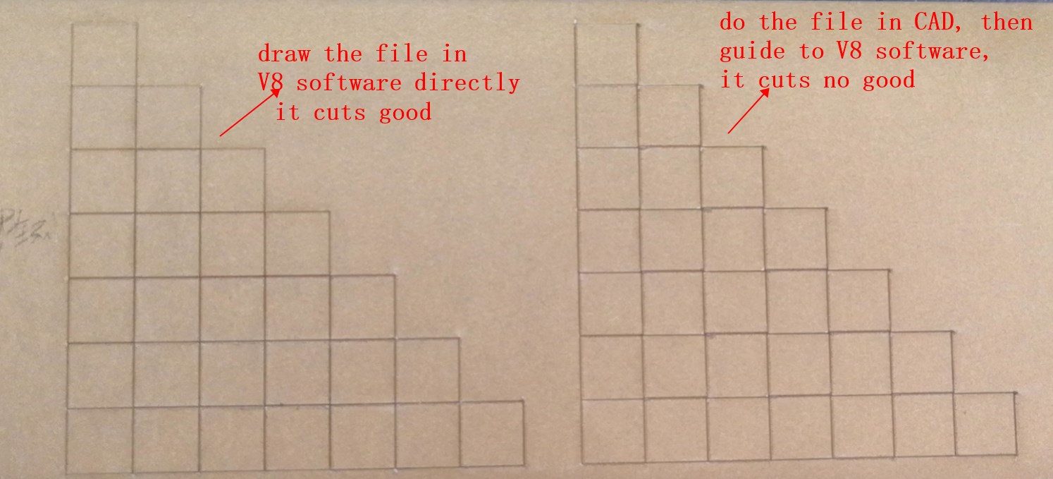
I don’t use RDWorks of course, I use LightBurn. This file was made in LightBurn. My puzzle file was made in Sketchup and saved as a pdf, and it works just fine on both a GlowForge and an Epilog. It also seems strange to me that importing a file would make any difference, or that the cut order should make so big of a difference even at low speeds.

I’d really appreciate it if someone could try this file and point me in a useful direction. (A temporary fix is setting cut order on my multiple puzzle file so each is cut in the same order, something I haven’t figured out but will ask about in a different post. That will solve the immediate problem but not the larger problem with misalignment!)

Thank you for any help or advice you can offer!

What software was this designed in originally? If LightBurn, how did you build this originally?

As I start to disassemble your shape groupings, I see there are some overlapping shapes completely covered by another shape, which should be understood or removed. I am going to assume these duplicate moves are causing the issues you see in the lineup of “corners”.

Yes, we are following this in your separate post - Is it possible to cut several groups with the exact same cut order inside each group?

Aha - so I do.That’s a good find! I will eliminate the overlapping segments and try the test again, although they don’t cut as I’ve selected “Remove overlapping lines” in the optimization settings.

However, no matter how many overlappings or duplicated shapes, my cutter (or any cutter) should to be able to position them precisely. I’d like to think I could stack 100 shapes on top of each other and have my cutter cut over the top of the shape again and again and every single shape would be exactly the same. Or maybe I’m wrong… you seem to suggest that overlapping lines are the cause of bad corners? I wonder why that cause errors.

Thank you so much for taking the time to take a look at this, Rick. Could you perhaps run a test cut on your machine with this file and see if you get the same problem? (I use low power to just get marking lines). Knowing whether or not someone else gets the same problem would be hugely powerful piece of data in my problem-solving!!!

This design was made in Lightburn by creating a square and using the grid tool. That seems to be why there’s a lot of duplicate edges as you’ve found by dissecting the file. I started with a complete square grid, and then I removed the upper right portion because that area contained no errors.

I should add that I don’t care about this particular design per se… my goal is not to get this to cut correctly because I want THIS design. This staircase design is simply complicated enough to cause my laser cutter to have alignment issues, issues that are plaguing my other designs. I’ve been operating under the assumption that the problem is either mechanical or something with the settings, so if I can use this to find different settings or a mechanical problem with the laser then there’s a good chance all of my other designs will cut correctly. If this issue is software then I can focus on workarounds (but I’m having a hard time wrapping my head around the idea that software could cause misalignment on a simple grid pattern.)

All of my other designs that I cut a lot are designed in Sketchup, exported to pdf, and then imported to whatever program. With my Glowforge, the pdf is sent directly to their servers and then sent to my cutter, with my friend’s Epilog the pdf is imported into AutoCAD and then sent to his cutter. Both of these work just fine. With my new laser cutter, I’m importing into Lightburn

If you have a design you are “cutting out” and you have overlapping lines there should not be any difference in the X Y coordinate position of the laser head when ‘re-cut’. Computers do thing the same way over and over and the first “C” in CNC stands for Computer. If your overlapping lines are not really overlapping but are slightly offset then you can get stepped cuts.

Otherwise you have a mechanical problem and the most likely problem is loose belt(s). With loose belts, which are loops, when you move in one direction there will be slack in the belt on one side of the laser head AND the lower return portion of the belt. When moved in the opposite direction the slack will end up on the other side of the laser head AND the lower return portion. In either case, the laser head is not moved to the exact computer controlled location even though the motor(s) have moved to these exact locations.

It’s a combinations of a less-than-stellar QC by the maker and a bad file, by the looks.

When you have a problem, go back to basics to resolve. You are having trouble with a puzzle? So try cutting three boxes in an L pattern that you’ve drawn as primitives and aligned inside LB.

If they are misaligned, chase the reason (likely mechanical) that is the cause. Once your machine is running true, sort out your conversion from one app to the other.

I use Sketchup, a lot, for buildings, mechanical devices, etc. Don’t use PDF - use a vector exporter.

I use this extension - available through the extension manager - and export vectors with zero problems.

1 Like

Loose belt would totally make sense, but the belt is tight and i just tightened it more as much as I could. No difference.

Good idea, get as simple as a file as possible that will produce the error. I’ll work on that.

PDFs from SketchUp work great for me, I’ve used them for years on two other laser cutters. Gotta be sure you have the print driver – when my wife prints as pdf from her computer the pdf contains an image. From mine, it contains vector data, which can be edited in LightBurn or other vector programs.

However, I always have to make sure the SketchUp window is showing exactly what I want to export, and I have a custom “paper” size that’s something like 800 mm x 600 mm just to be sure I catch the whole model.

I have a very illustrative example now that I hope will shed some more light. Have you ever seen something like this or can think of what could cause it?

In the first picture below is two sets of 10 lines, one set above the other. The top set cuts first, in the order and direction as shown with the numbers 1-10 and in the directions shown by the arrows.

Next it cuts 11-20, going in the opposite direction, as the numbers and arrows show. They miss alignment in the middle.

(The lines were made by drawing one 15 mm line and then using the grid tool to create an array with 10 lines evenly spaced, 10 mm apart. I assigned these a cutting priority from 1-10 to control the order so they cut left to right. Next, I copied the entire group and placed the copy underneath. I then changed the priorities from 11-20 so that this group would cut in the opposite direction. They are dead accurate on top of each other in the file, the top half an exact copy, moved 15 mm down, unrotated.)

Close-up:

As you can see, the cuts do not align in the middle, but they align on both ends. Strangely, the misalignment gets worse and worse as it reaches the middle, and then better and better until it lines up again at the end!

Next, I started with the same line segments 1-10, copied them and placed them underneath, and then set the priority so they would cut left to right, the same direction as the top part.

Here is the result: it cuts fine. No alignment problem.

So, there is a difference in the laser position when moving left to right compared to moving right to left!

Just for kicks, I was interested in how the error gets worse and worse to the middle, and then better and better until it aligns again at the end of the row. So I did a version with 40 double lines. It also gets worse and worse, but only for the first 3-4 lines and then it holds a steady error of about 0.1 mm until near then end, where it mysteriously realigns again.

(Underneath is a rotated test where I made the lines very long to see if y-travel made a difference, but it did not.)

PS: I’ve tried Rising Edge on and off, I’ve tightened belts and screws, I’ve cleaned and lubricated the rails, I’ve adjusted acceleration and speed (including all the way down to 10 mm/s2 and 10 mm/s) with no effect, and every time I have a file with an error it is 100% reproducible.

Are you shore that your Y axis is not giving you the problem. Are both bearings running smooth. It look like your Y axis drive is a bit misalligned.

too-tight is as problematic as loose. It should be finger-tight, no more. just tight enough that the belt won’t ride up the crenelations in the pinion.

1 Like

The picture is not square, and the wood is not always at 90° when I put it in. When cutting grids, one square at a time, the vertical lines are full of misalignments and the horizontal lines are perfectly aligned, so y is finding the exact correct placement but x is full of tiny errors.

I’'ve tried it very loose as well and get the same results.

Then look for something else which is loose on the X axis. Are there 2 motors for the Y axis? If one has a loose coupler that might cause the problem. How about loose bearings on the X axis. It is not the software and not the firmware so look for something which can cause wiggle when the laser head is moved in one direction and the other.

So between ‘very loose’ and ‘too-tight’ you will find the appropriate tension.

Too-tight will wear out cheap bearings and eat your belt. Too loose may slip a tooth, but won’t do damage.

1 Like

and if you look at the drive gear at the stepper motor when things are moving you should not seen the belt move up/down ANY BIT right where it enters and exits the drive gear. Too loose and you’ll see movement and you tighten just a bit more until you see no movement. Last check is a high speed move from one end to the other, ie high acceleration and tension put on the belt.

If that doesn’t fix it then you look for mechanical movement slop like bearing, wheels, mounts, etc.

Hi Doug, that’s a great tip for adjusting tension. I’ll give that a look.

(… and the long horizontal lines at the bottom of this picture are actually vertical lines, the material was turned when I cut them). Thank you for taking a look … I will check all bearings again.

You should also check the pulley mounted to the stepper. If it was installed carelessly, it may have a bit of slop. Usually, there is a flat on the stepper axle that the grub screw tightens to first, (as precisely in the center as possible), then the second grub screw gets tightened to the round side of the axle. If the screw on the flat didn’t get centered, then there can be a couple of degrees of slop.

1 Like

Thanks Ralph, the ordering you’ve done avoids all problems with this design… however it is not this design I care about, but all designs I cut. Intersections should match up regardless of cutting order or direction.

1 Like

Thank you Doug. I can’t find anything loose, it’s all tight as can be. Checked after loosening the main gantry belt and the belt between the x-stepper and then main belt.

I have two motors for the Y-axis, but Y-direction seems just fine. I did my vertical line test again. I cut 20 vertical lines from left to right and another 20 again left to right undernearth. They line up perfectly. I then change the vertical cut direction on the set underneath so that Y moves in the opposite direction, and in both cases they meet exactly. I did not remove the y-axis belts to check for any looseness on the y-motor mounts because I don’t think these are a problem, but I may do so as I’m getting desperate!