Hi
Laser: xtool D1 pro
Computer: Lenovo Windows 11
Ok, so I was able to figure out how to make a jig. I think it should work based on the videos I’ve watched. I placed the targets and I cut out the appropriate areas.
The issue is I’m using an Xtool D1 pro. I am aligning the laser with the crosshairs that the laser produces for alignment (i.e. I place the crosshairs over the first target. When I go to select the second target, it jogs to a position that appears to be about the same distance as the distance between the crosshairs and laser. I know when using creative space you can choose how you want to align something (with either a light from the laser module or from the crosshairs). I thought that lightburn was supposed to automatically offset everything to account for this distance between the laser and crosshairs, but it doesn’t seem to be doing that. Is there a setting I need to push to make it account for this? Or is there a way to have lightburn choose the laser as the way to line up the target and laser?
I would think it would apply the offsets to it anytime, but I’m not sure, never used an offset pointer with my diode machines… just turned down the power really low.
If your machine homes, you should be able to make a jig that doesn’t require you to align the head… that’s pretty much the idea of a jig.
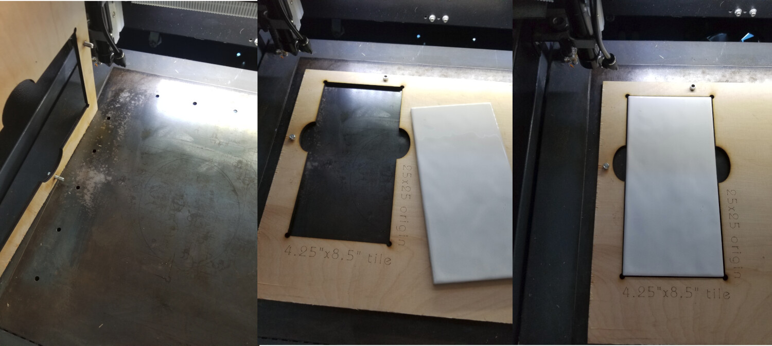
Here’s one on mine for porcelain tiles. When I make it, I always lay it out, so I know what the coordinates are for one of the corners. I don’t have to do this, I can import the design I used to cut the template and align where I want it in the jig outline… running in absolute coordinates.
Hi
I was having issues with starting my laser from the homing site that it wants to start in. Whenever it gets near a limit, it says out of limit and shuts down. I don’t know how to re-calibrate the working space (that’s a problem I’d like to save for another day if I can). When I’m working out in the middle of the working space it seems to work fine.
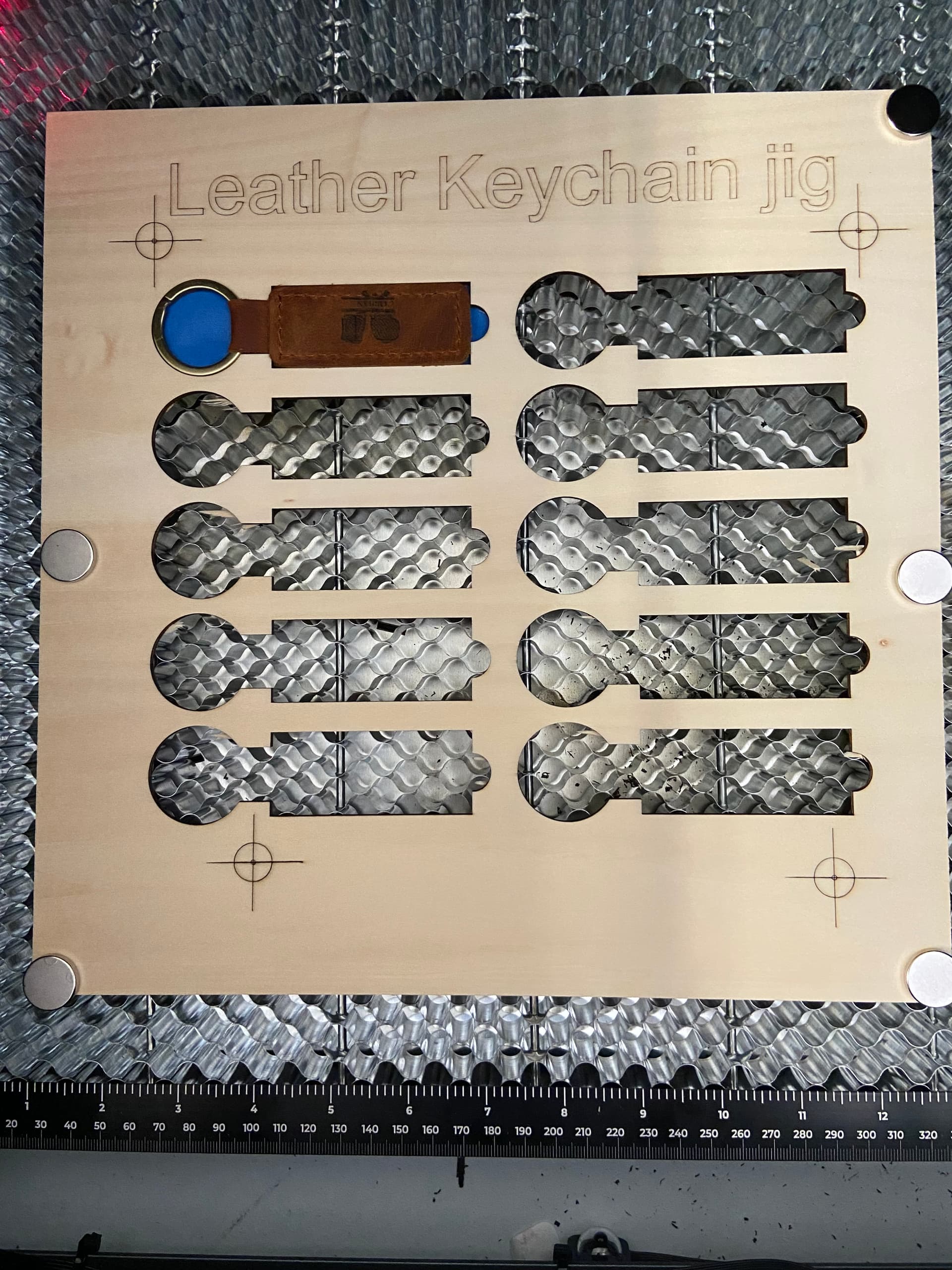
I use neodymium magnets to hold down the 3mm basswood plywood while the jig cut. I made the jig a tool. You are saying if I just lay down the jig, start from the top left corner of the tool, then I should be able to engrave accurately?
I placed the targets offset from the corner because otherwise the laser would push the magnets around and I didn’t want to lose positioning. The magnets are strong and seem to be holding the jig in place.
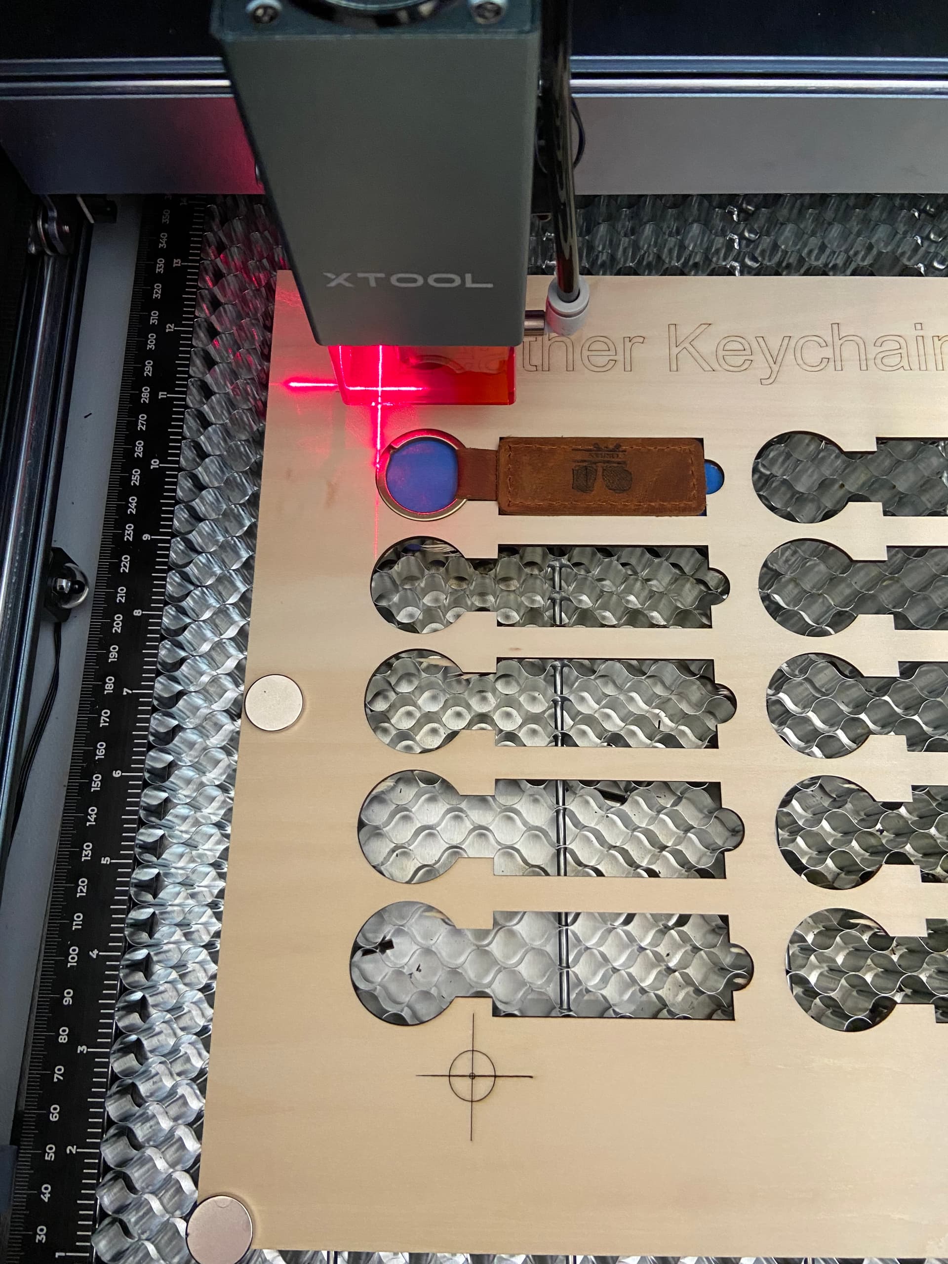
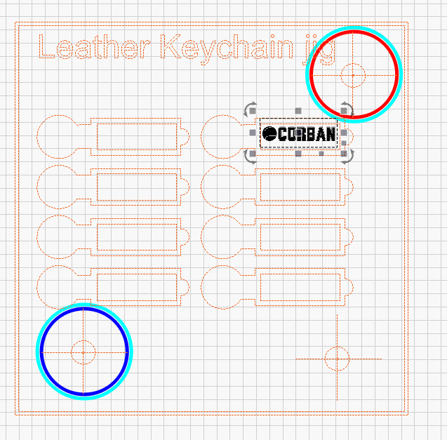
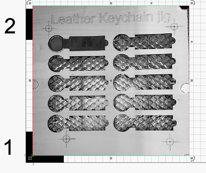
I’m attaching two photos. One is the jig itself and one is the jig with the laser (approximately) lined up with the first target (I didn’t bother to get too accurate for the photo).
When I try to align to the second target in the bottom right corner it homes to a location approximately the distance between the crosshairs you see in the photo (with the laser module) and the actual laserbeam itself.
I did something (i’m not sure what) that disabled my ability to use print and cut. I click set position 1 and nothing happens. When I had done this previously it accepted position one and asked to tell it to jog to position 2. Lightburn is killing me today.
Go into your device settings and change the offset.
The d1 laser cross hair is offset approx 16mm to the left of where the laser burns. If you enter minus 16mm into the “X” box, the laser will move 16mm LEFT when it starts. a plus 16 will move it to the RIGHT and you’ll be way off your desired start point. You can enter offsets into the “Y” box as well. Plus moves the start point UP and minus moves it DOWN.
For my d1 I ended up with minus 16 and minus 1 offsets.
I used some scrap, OK, failures, to fine tune. Made a dot, put the cross hairs on it then made a box with the job origin in the center. A straight edge laid corner to corner should go through the dot. If not, change the number until it does.
Don’t forget, where you set your origin determines where your cross hair and star point are.
Wow
Ok that was much more tedious than I had hoped it would be, but I managed to get results I think that worked. My offsets seem to be -18 and -1mm. It took alot of trial and error until i finally was able to match up my starting line with my test line.
I basically told lightburn to burn a large “plus” sign, I lined up the red crosshairs on the plus sign and then I deleted that, drew a box and used current position as the start point. After multiple back and forth I finally figured it out. Maybe it would have gone faster if i had done math correctly I suppose. Either way, i finally finished up with a box and the top line of the box lining up with the horizontal aspect of the cross hair.
Thank you for your help. I will now try to re-attempt the jig and see if I get success.
I want to scream. I tried the jig…i don’t know what the issue is. I used the new offsets I programmed. Do I want align the outputs and scale or not? I don’t know anything about that. I think the videos I watched used an older version of lightburn that didn’t ask that question (regarding scaling or not). Or they just didn’t discuss it (Or i don’t remember the discussion?).
When i told it to jog to the second target, it was way off. I may not have built the jig correctly? I didn’t alter anything after making it a tool layer (i.e. i didn’t move any of the targets).
If I measure the target to the crosshairs I get a little over 18mm (18.35mm) that’s its off to the right. I can’t get a good measurement to the laser itself. Am I doing something wrong with the offsets? At this point I’m about ready to toss this thing in the trash.
i don’t understand why there seems to be inconsistency between the jig creation and the misalignment when using it as a tool
I have a question about the creation of the jig. First of all, when I make any jig it seems that when i choose the second target, the laser nearly always lands a pretty similar distance from the actual target. I can’t adjust the piece of wood without losing alignment with the first target (the distance between the laser and the actual second target point is lateral approximately 18mm).
Is it ok to move the laser back to the target with lightburn and align the laser and target? will that help? So far it hasn’t seemed to help, but I wanted to know if that was standard practice. Ultimately to me it seems like lightburn just doesn’t know the coordinates. And I don’t know how to calibrate those coordinates properly.
When I took an image into creative space I was able to get it to align a little better (though not perfect), but creative space seems much more limited and I want to be able to make multiple laser engraved items at once rather than one at a time. And I want to be able to do it repeatedly in a similar manner (i.e. i want repeatability).
Any advice to fix this issue is welcomed. I apologize for all the posting. I am just trying to figure out how to resolve this issue. So far every solution I’ve tried has resulted in a similar issue.
For anyone reading this, I think figured out a solution (or at least a 90% solution).
I had set the offset to -18mm because that’s what it seemed to be between my red light crosshairs and the actual output of the laser (based on repeated testing of different offset sites). I disabled the offset and tried to center the laser using the blue light (which I find more difficult because the diode laser is so close to the material that its hard to see its actual location).
When I did that, I was able to get the computer to jog to the correct location on the second target.
The only problem that remains now is that the location I chose on the lightburn software doesn’t match up perfectly with the actual location. You can see the results in the attached image. In the screenshot the image to engrave it shifted to the top of the “engraveable area”, but when it actually engraves the image is nearly perfectly centered in the horizontal axis. Unfortunately, its shift to the left slightly (maybe 1-2mm?).
In post #5 and #10 of the first thread you have examples of jigs/templates.
In second thread post #3 you have an explanation by @thelmuth.
To get you started because it´s important to have registry points it´s the key to a good connection between Lightburn and a known laser position.
I believe you are complicating things with Print & Cut, but I may be wrong.
I’m sorry. I’m still trying to understand. I am sure I’m missing something that is simple and may be common sense for most users. I thought that my using print and cut and aligning the targets that I was creating registry points. Is this not the case? Are you referring to making a specific user origin site? If that’s the case is there a typical origin site that is recommended?
@NicholasL
hi Nicholas. I did that. Or tried to do that. I tried to line up the targets with the actual laser rather than the crosshairs. To do this I also turned off the “disable offset”, but maybe I need to re-enable offset and try to figure out an offset using the blue light directly from the laser.
Its so much harder to view the laser because the laser sits so close to the material, but I’ll keep trying to optimize it. After thinking about it, its possible the laser wasn’t perfectly aligned on the second set point, but I remember checking to be certain. I’ll keep working on it.
Just an example: You need your honeycomb in a fixed position with your laser, using absolute coordinates for general use you can use an L shaped fence (even DIY with the laser) (#1) fixed to your honeycomb that you know the fixed coordinates of the inside corner in this case (X10,Y10), for more precision you could place another registry point (#2).
Then you design and cut your Template, after that you should put your design in a Tool Layer an Lock the shape and then Save as (i.e. Leather_Keychain_Template).
When you want to engrave more keychains just grab your Template place it against the fence fix it, open your File, place your designs and engrave.
I hope you understand what I´m explaining.
Just remember a few videos from Rich:
Your jig is good, normally when making a jig like that the outside of the jig is cut at the same time and so the outside edge of the jig can be used to align against with a framing pass (continuous), or put some masking tape onto the honeycomb where the frame happens (at the very least a couple of pieces in diagonally opposing corners) and etch the border of the jig into the tape (in absolute mode after homing), so you know exactly where to place the jig.
Or as @parsec has explained, it is useful to create a L-shaped part that fits onto your tray always in the same place, you can even cut the inside of the L using the laser, then you have a corner at a known absolute position for placing your jig.
Thank you everyone. I will watch the videos and I’ll try to digest everything. This gives me some things to go on and try. I will try and see if I can fine tune this whole thing. Thank you so much for your time and advice.