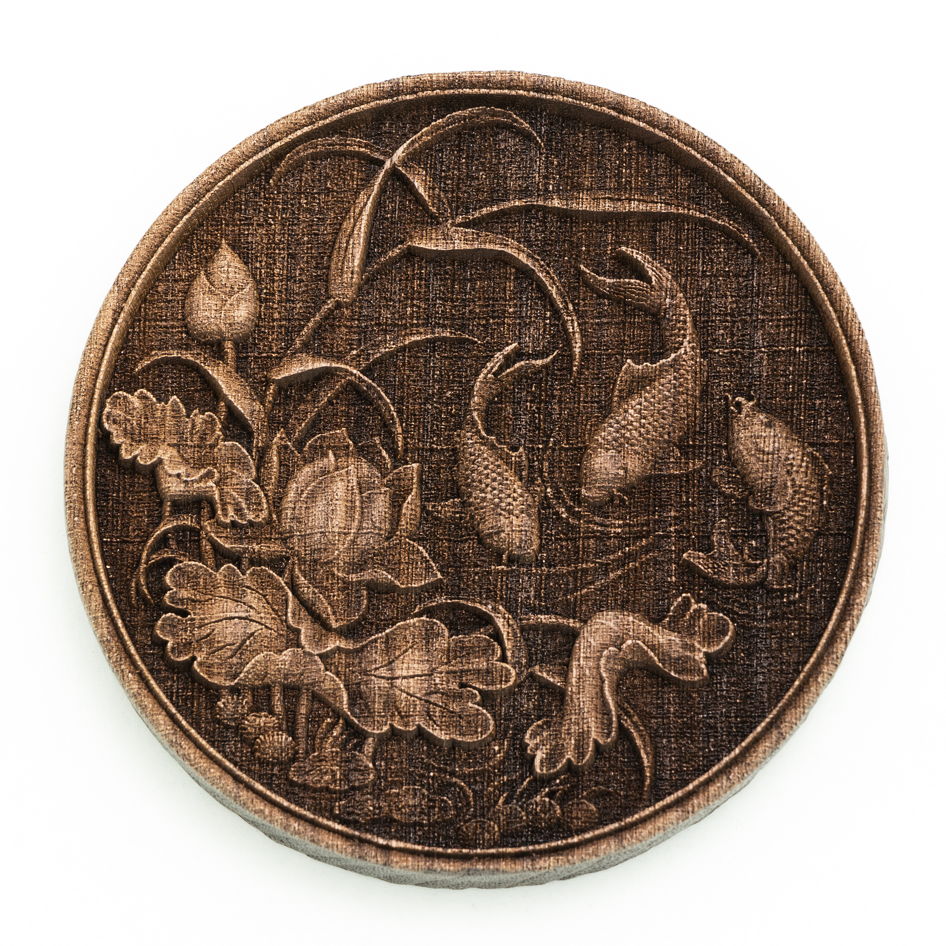
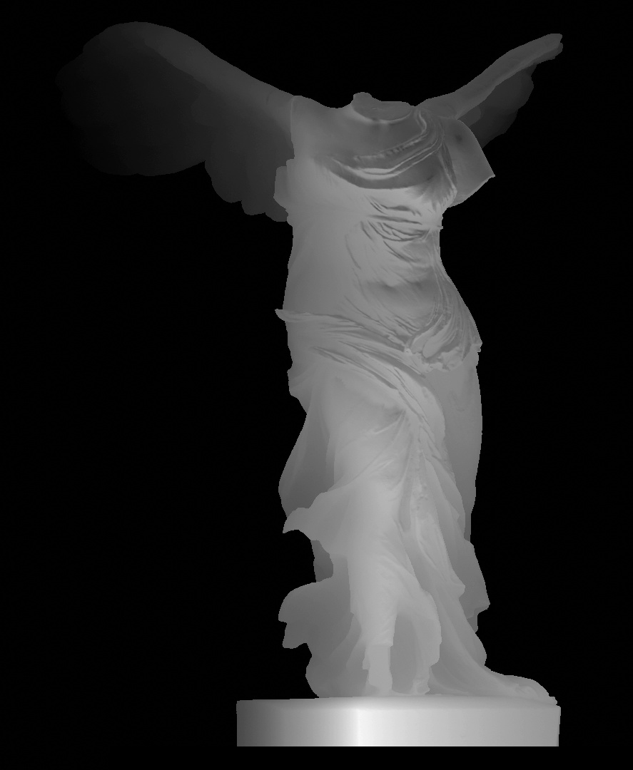
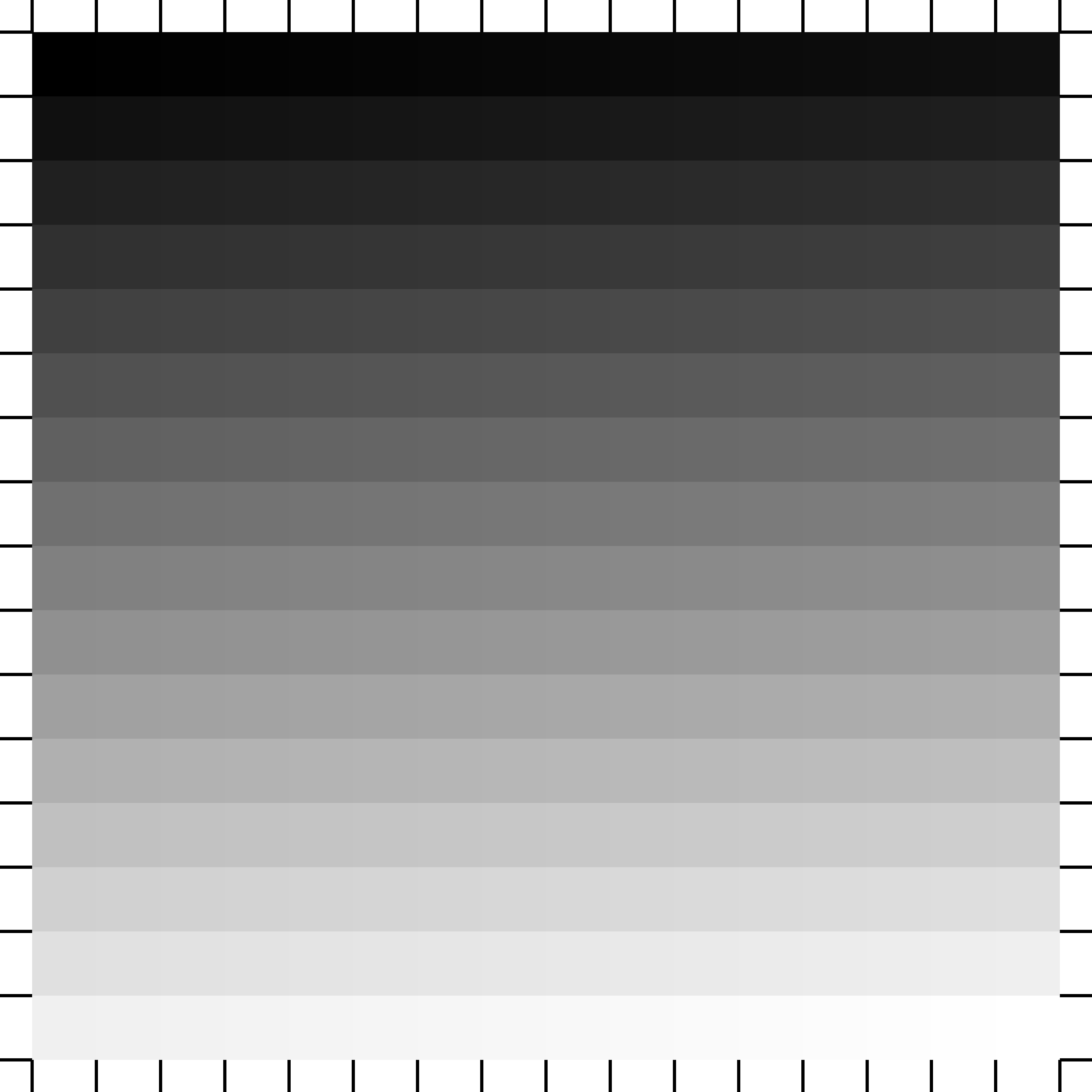
This koi scene and the grayscale test square below are my first attempt at 3D laser engraving. Both are 0.5" thick pieces of walnut. This circle is 3.5" in diameter. The max depth of the burn is 0.15". I burned it with LightBurn on a 100 W CO2 laser in a single ~40 min pass.
LightBurn Parameters:
Mode: Image
Speed: 150 mm/s
Max Power: 100%
Min Power: 19%
Bi-directional
scanning: On
Line Interval: 0.03 mm (847 DPI)
Image Mode: Grayscale
Number of Passes: 1
Gamma: 0.5 (In Shape Properties)
I cleaned the char off by aggressively scrubbing it with a toothbrush using dish soap and water. I finished the piece with two coats of water-based polyurethane spray (Varathane satin).
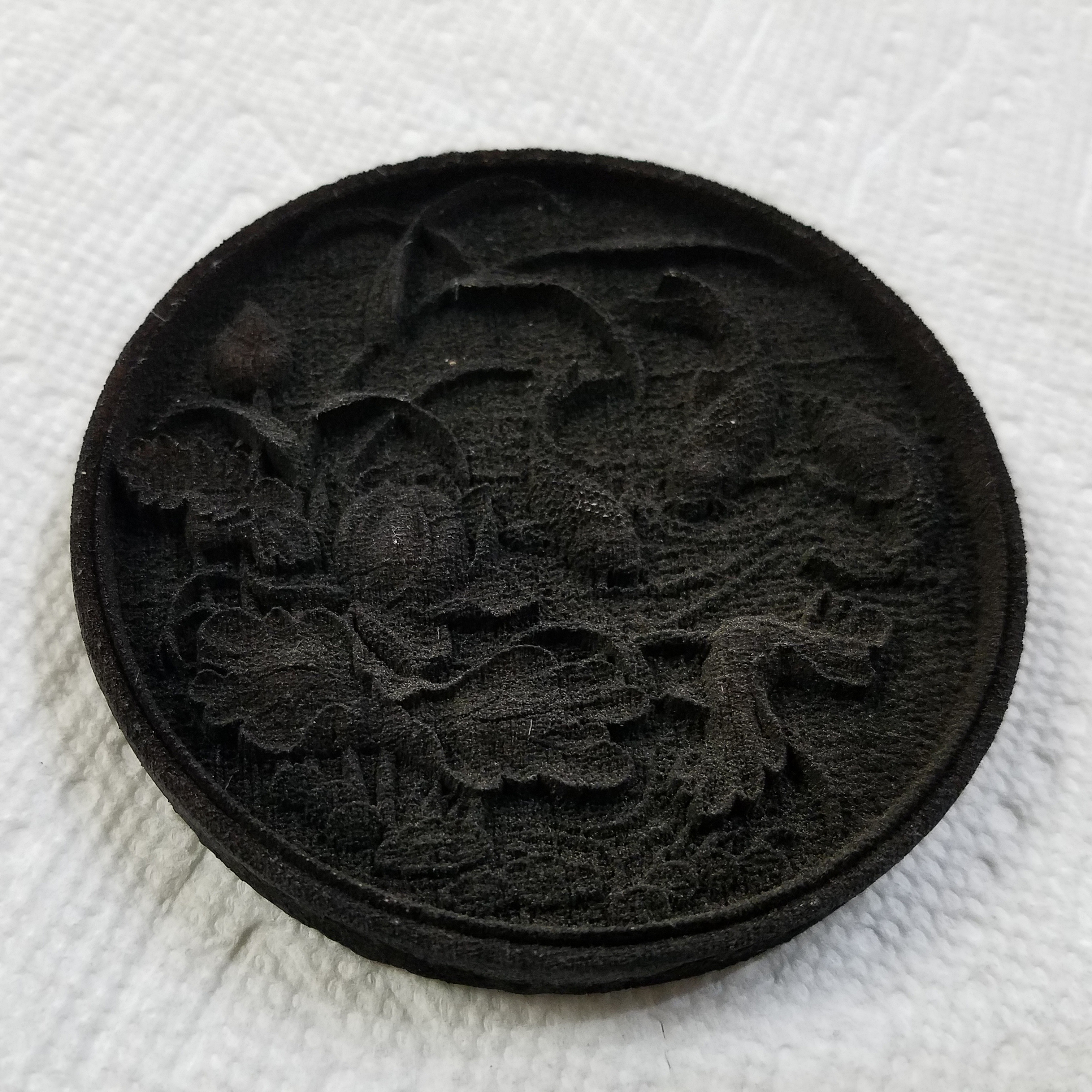
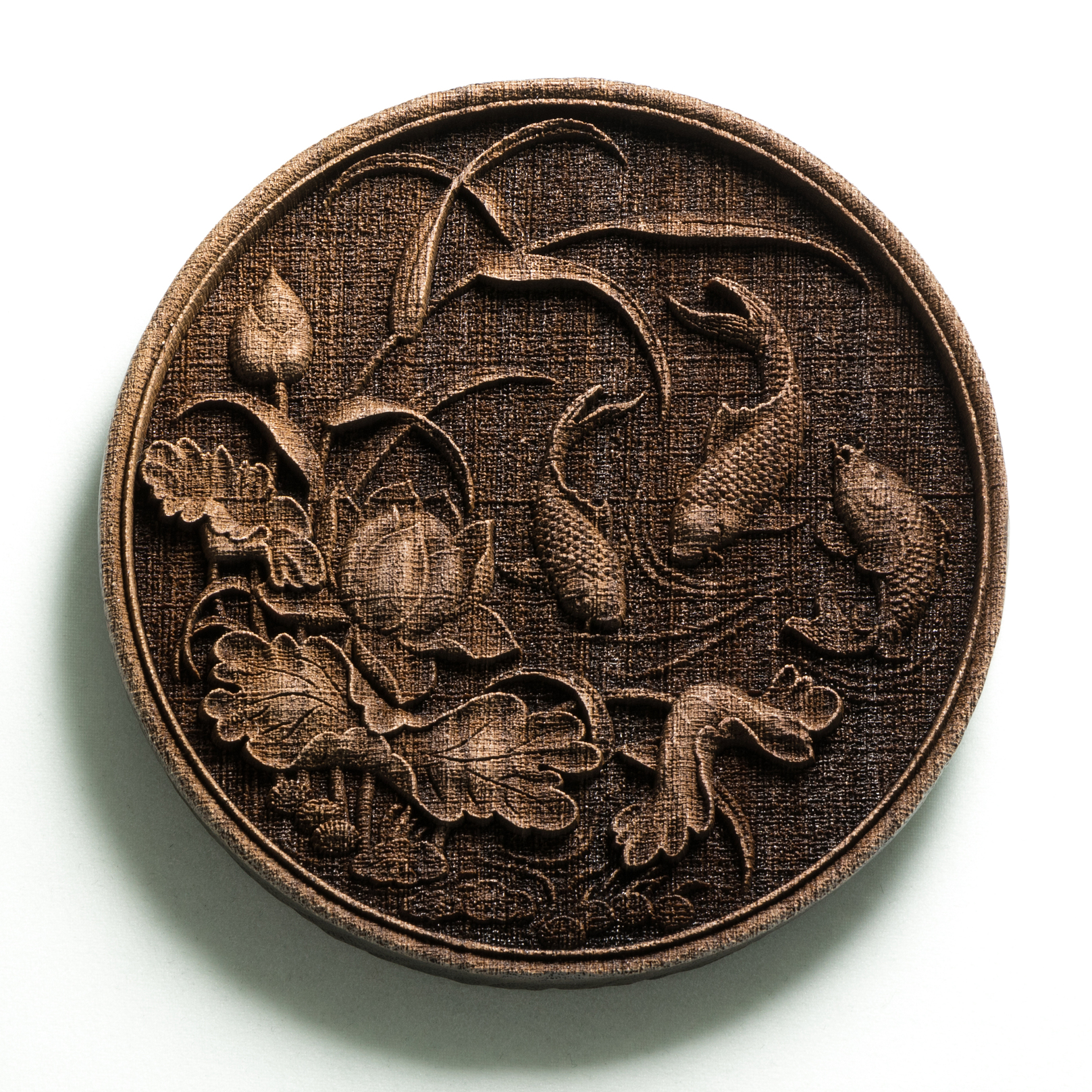
Here is another finished shot with harsher shadows that accentuate the depth:
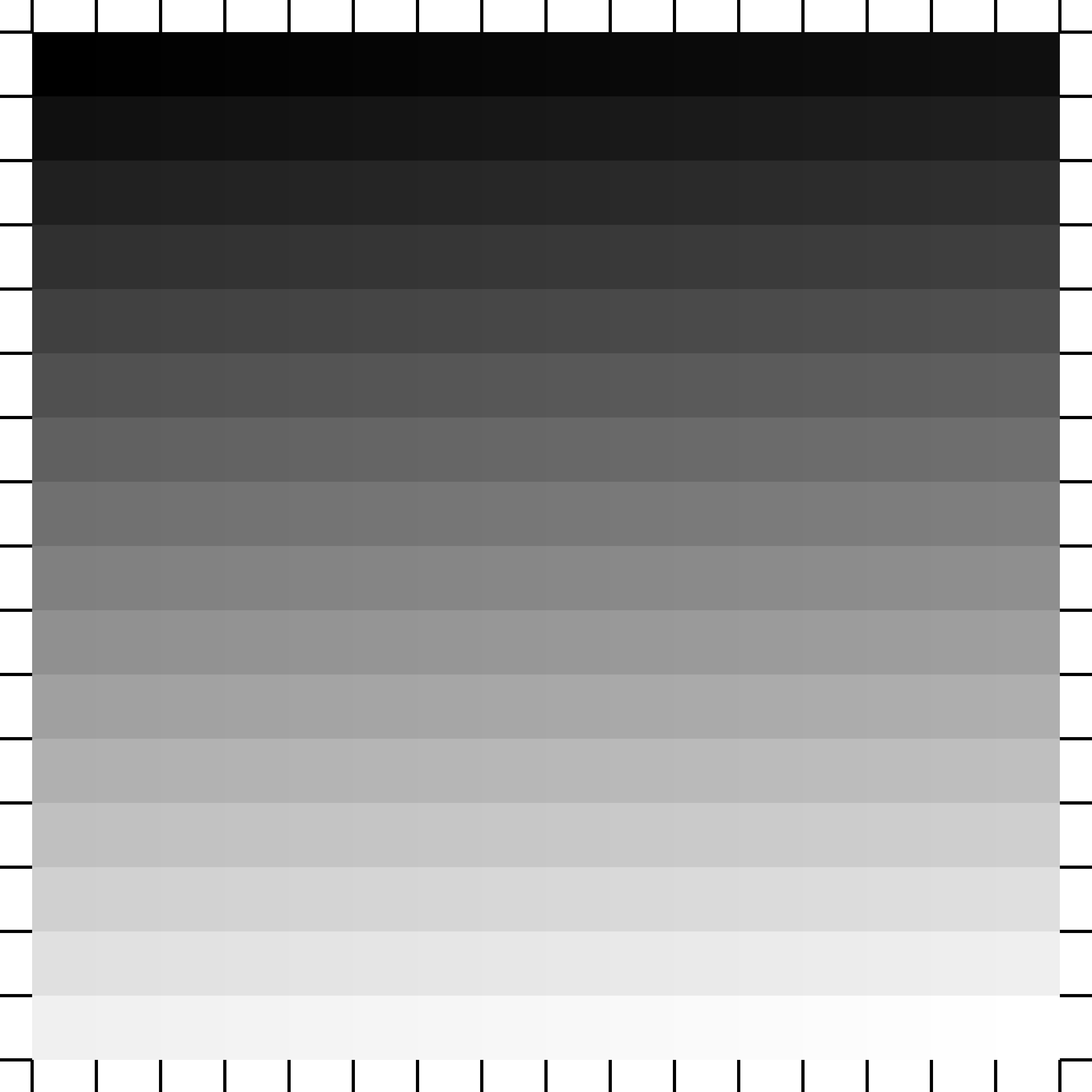
I used the same parameters as those listed above except for the min power which was 12% instead of 19%. 12% corresponds to the point at which this laser begins to fire. I switched to 19% for the final koi burn as the test pattern showed no burning for the first 1.5 rows.
I generated the grayscale test square image with this python script that I wrote: grayscale_square_gen.py.txt (967 Bytes)
I found the koi scene image using Google image search for depth map images. However, it should be relatively easy to generate a depth map from a given 3D model. I found this tutorial but haven’t tried it out yet: Creating a Depth Map from a 3D Model for 3D Engraving.
Thanks for the script I have been wanting to look into learning this.
How do you go about using it, please?
You’ll want to change the extension of the script from .py.txt to .py (I couldn’t upload it with the original extension). Next you need to install python if it isn’t already installed: Download Python | Python.org . You’ll also need to install the Pillow python library. Pick the version matching the python version that you installed: pillow · PyPI .
To run the script use one of these commands in a command window: (if python < 3.0): python full_path_to_the_script/grayscale_square_gen.py (if python >= 3.0): python3 full_path_to_the_script/grayscale_square_gen.py
The script will output grayscale_square.png in the same directory that the script is located in. It will be identical to the grayscale square image shown above.
Some people make them manually in Photoshop but another way to do this is to start from a 3d object and create a depth map. In Blender, it’s called Z pass. Essentially a Z pass is a visual representation of the distance from the camera to each pixel, meaning it ignores light sources. Anything you can 3d model you can convert. Zbrush can generate them as well. If you can’t 3d model you can download stls from thingy verse, turbosquid etc. Here’s a tutorial on how to do this in Blender.
@dpcollins - There is a YouTube channel by a SarbarMultimedia which tries to explain the VERTICAL lines in finished piece in terms of “high frequency impulse engraving.” A bit technical for most hobbyists (I don’t understand it all myself), but pretty interesting. Basically, he comes to the conclusion that it’s the stepper motors which do this in relation to the speed of the laser. https://youtu.be/mXIDwQxhX3k
Thanks for your tests. I look forward to trying them on my machine.
@JBrondos - That is an interesting video! I ended up watching several of the videos in his series investigating the vertical line behavior. My understanding is that the vertical line pattern results from the x-axis sweep not being at a perfectly constant speed (e.g. 200 mm/s). Instead there is a minute amount of acceleration and deceleration at the beginning and end of each stepper motor step (e.g. 1/200 of a stepper rotation) which worked out to 0.24 mm of linear motion on his laser. This effectively results in the laser dwelling slightly longer at the beginning/end of each step and thus burning slightly deeper.
His best mitigation method was to run 5 low intensity passes which alternated between x-swing and y-swing. This resulted in the previous vertical line pattern showing up both vertically and horizontally but perhaps less noticeably.
Since I can only utilize a laser in a shared shop environment, I’m not interested in approaches that require multiple passes. That would take way too much time. My last 3D engraving (~2.5 in x 7 in) took 1.5 hr for a single pass.
That being said, his investigations did give me an idea for a potential way to mitigate the vertical line pattern. We can’t really improve the physical stepper motor behavior; however, we can affect the instantaneous power during 3D grayscale engraving relatively easily. This would involve generating a grayscale image that is effectively the inverse of vertical line pattern. Burning this image should theoretically eliminate the pattern in a manner similar to noise cancelling headphones.
Making this inverse image would unfortunately be challenging and finicky. My first guess would be to use a tiled positive section of a cos() or cosh() function with very low amplitude (perhaps 5-10 /256). The period would need to match that of the observed vertical lines. A test pattern could be generated with rows of these pixels (perhaps 2mm tall) which are then stacked vertically and shifted horizontally minutely. Burning this image would allow you to figure out which shift amount (phase) would be needed to cancel out the pattern for any given absolute X position on a particular laser.
There are several variables that would affect the precise pixels values needed in the inverse image. These include the scan speed, laser commanded power, laser true power (smoky lens/mirror, aging, temperature, etc), material being cut, and precise gray level at a specific pixel within the intended grayscale image being burned.
Even after figuring out the proper inverse image, the 3D engraving workflow would be annoying. You’d need to place the material to be etched on the laser bed and secure it very well. Set the origin as desired, then move the head only vertically to a scrap piece of the same material. The test pattern with inverses at various phases would be burned to figure out which phase is needed for that origin X position. Then the inverse would need to be applied using that observed phase in photoshop (somehow). The final image with the correction applied could then be sent to the laser to be etched. This would involve a lot of scripting/programming as well as a lot of testing and tweaking to get right.
I think that I’m content to live with the vertical line pattern for now. It would be great if someone else wanted to attempt burning an inverse of it though.
I know this is an old thread but I’m just getting into this 3d engraving with a laser my first couple came out like yours. But then I tried max power 50% then on min power I did 0% wasn’t sure it would fire that way but in the gay scale setting it did and came out with a great looking piece without any burn on the parts that were meant to be untouched and those were left untouched.
Just wondering if you have tried this and if I’m on the right track or not any help would be appreciated thank you Tom
@Chevrc - Is there a particular aspect of your laser engraving that you want to improve? Could you post a picture of your piece along with the source image?
If you want to test the capabilities of your laser more, then I’d suggest burning my test image from above: https://forum.lightburnsoftware.com/uploads/default/original/2X/5/5c858ec5f774402e478c83eba6dc9eb277adca00.png . If you use Min Power = 0% and Max Power = 100%, then you’ll see the largest possible range that your laser can produce (for a given speed and line interval). If your laser doesn’t fire below X%, then you would see that a portion of a row, or perhaps a few rows of the test pattern are completely untouched. You could approximate X = (how many rows + fraction of a row are untouched) / 16. Similarly, you could approximate your preferred max power by seeing how many rows out of the 16 you have to come in from the darkest/deepest to reach the one that you like. Note that the gamma setting (in shape properties) also impacts the output (i.e. if the test pattern slopes linearly, concave, or convex).
Thank you I will try the test image. I have never messed with the gamma setting’s am I missing a lot adjustment possibility’s not changing the gamma setting’s . just when I think I am getting the hang the hang of this a whole new world open’s up with a new discovery of what this laser can do LOL. Thank you for taking time to help me I really appreciate it.
I attempted to reply from my gmail about some of the efforts I was trying today. Not sure it actually got to you, Can you validate it did or didn’t. If not, do you haave an email I can send directly to? My email is robsandstrom56@gmail.com, Thanks
@robsandstrom you might want to try adding the “atXXXXX” in your message so the person you are trying to communicate will know this, others will know this and that person will get a ping from the system that someone is talking to them.
@robsandstrom it doesn’t help there are a bunch of different forum types and that some people are actively monitoring some forums with phone apps and others just pop in every 3rd blue moon. It does seem that mentioning a person directly with that @ sign in your reply gets noticed the most.
  File "C:\Users\xps\Desktop\greyscale_gen\grayscale_square_gen.py", line 24, in <module>
    img.putpixel((i * n + tick_length - tick_width / 2 + j, k), 0)
  File "C:\Users\xps\AppData\Local\Programs\Python\Python310\lib\site-packages\PIL\Image.py", line 1868, in putpixel
    return self.im.putpixel(xy, value)
TypeError: 'float' object cannot be interpreted as an integer
@GaS - It looks like python behavior has gotten stricter since I original wrote the script. Apparently the ‘/’ division operator now always outputs a float type. Changing those to the ‘//’ integer round-down division operator should fix the error. Here is an updated version (be sure to remove “.txt” from the end of its name after downloading): grayscale_square_gen.py.txt (967 Bytes)
Here is an alternative version of the script that uses transparent pixels instead of white around the edge tick marks. This is helpful because transparent == laser off regardless of the Min Power setting. grayscale_square_gen_transparent.py.txt (1.1 KB)