I’ve thrown this out a few times, now I’m concerned because I cannot get the rubber band frame to work at all. The Frame commands seemed to have reversed on (both) of my lasers. At first I didn’t mind because I just used them in reverse and everything was good. I went to trace a circle to see the path that it would take and it only produced a square which doesn’t really tell the whole story of the burned area to be affected. At first I thought it was just my CO2 laser but now my diode is doing the same thing.
Wondering if anyone has encountered this and rectified it? I know when I mentioned it before, nobody had encountered this so not much chances here, but you never know.
I use a Mac, might have something to do with it.
@LightBurn do you think an uninstall and reinstall might give me any chance at rectifying? I’m not hugely familiar with Mac to be honest. I’d try deleting all registry files associated with Lightburn after uninstall but not certain Apple works like that. Anything you can think I can try?
Hi Craig - are you running the latest version of LightBurn (1.4.00)? I’m not able to reproduce the behavior you’re seeing with either a CO2 or a diode laser - both framing options are working as expected here.
What Start From mode are you using? Is this happening for every project, or only some in particular? If it’s some in particular, please share an example project file here.
Uninstalling and reinstalling LightBurn alone almost never helps, but sometimes a ‘factory reset’ can help by reverting a settings change that’s causing an issue - no setting that could cause this behavior is coming to mind for me, but it doesn’t hurt to try. Please note you’ll need to setup your device profiles again after this.
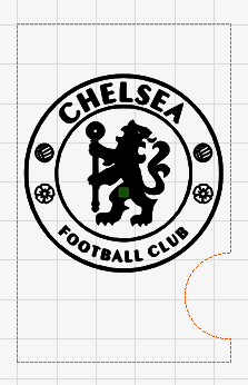
Hi Tyler, yes I am running the most up to date version. Start mode is Current Position. Occurrences seem to be totally random but you have me wondering if I created something screwed up a while back and have just been copying the file over and over as a start point and that is why only some are screwed up. I will attach a file that is reversed below (Chelsea). When I frame (cut boundary) it behaves like the rubber band and vice versa.
This is the file that got me concerned. When I trace this with the cut boundary (behaving like rubber band), it only does a square, not a circle. Wondering if that’s just because it doesn’t trace circles. Regardless, when I frame with rubber band it does the full rectangle shape. So, assuming it doesn’t do circles, the two are just reversed.
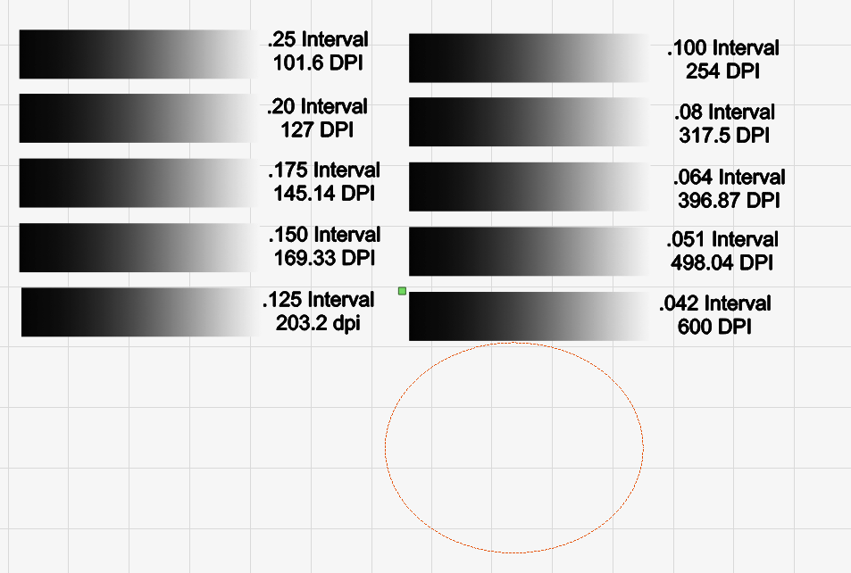
The second file “Line interval DPI settings” works 100% proper.
I think I’m going to save the factory rest option until the very end. I don’t want to lose everything I’ve saved and have to start over from scratch.
Thanks for these. I’ve reached out internally for further input but here’s what I’m seeing -
For framing, Tool layers are meant to be used for calculating origin, but are not meant to be framed themselves. You will see this behavior more clearly if you use a corner location for your job origin - the green square that is currently centered on your Chelsea graphic will move to a corner of the outer Tool layer. Then, if you frame (regular frame, not rubber band) with that corner job origin still selected, you’ll see the laser move in a bit from it’s current location/job origin, and then frame a square around the circular Chelsea graphic.
What you should see when you select the rubber band framing option is similar behavior, only after moving in a bit from the current location/job origin, it should frame a circle around the circular Chelsea graphic, instead of a square. What I believe is happening is that rubber band framing is currently incorrectly framing Tool layers, rather than only using them to calculate origin.
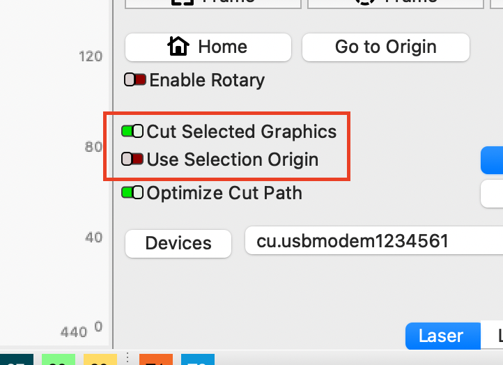
Try this - enable ‘Cut Selected Graphics’ but leave ‘Use Selection Origin’ disabled. Then, select the Chelsea graphic only (do not select the Tool layer), and try framing it with the different modes. They should work as you’re expecting.
Hmmm, that kind of sucks. I depend on the tool layers all of the time to tell me where the extents of my part are but not to burn anything. Like the image below. I have a shape that is almost round. If the laser travels around the outer perimeter, I know that it will be centered… I honestly use this for that purpose all the time. That’s why it has the “Frame” box to select/deselect in the layers screen, no?
Another issue that just popped up, wondering if you could comment. I’ve been noticing for my speed to move my head at (in the move screen) if my dimensions are set to inches the gantry moves extremely slow, but if I switch to mm, it goes back to normal. The units do not change however on the move screen. Always mm/s, so technically not true. Is this normal? Perhaps I need to put a ticket in for this to be looked at?
Thanks for the help here. I tried the cut selected graphics and I think I will stick with the other method instead and just take my chances, it’s a little more difficult to achieve what I want using that. I really like having the ability to trace the tool layer.
Also, the speed and power are affected by changing those units. Is it supposed to be like that as well? If I go back to the Lightburn settings I see that if I toggle back and forth between inches and mm for my units, it changes from mm/sec to inches/mm/sec so I’ve answered my own question there. I don’t really understand why it does that though. Is there an explanation of what that really means? Why is that an option, just seems a little confusing. Regardless, I know now so that’s good and i guess it also answers my last question, I just don’t understand why it’s even there… anyway, thank you!!