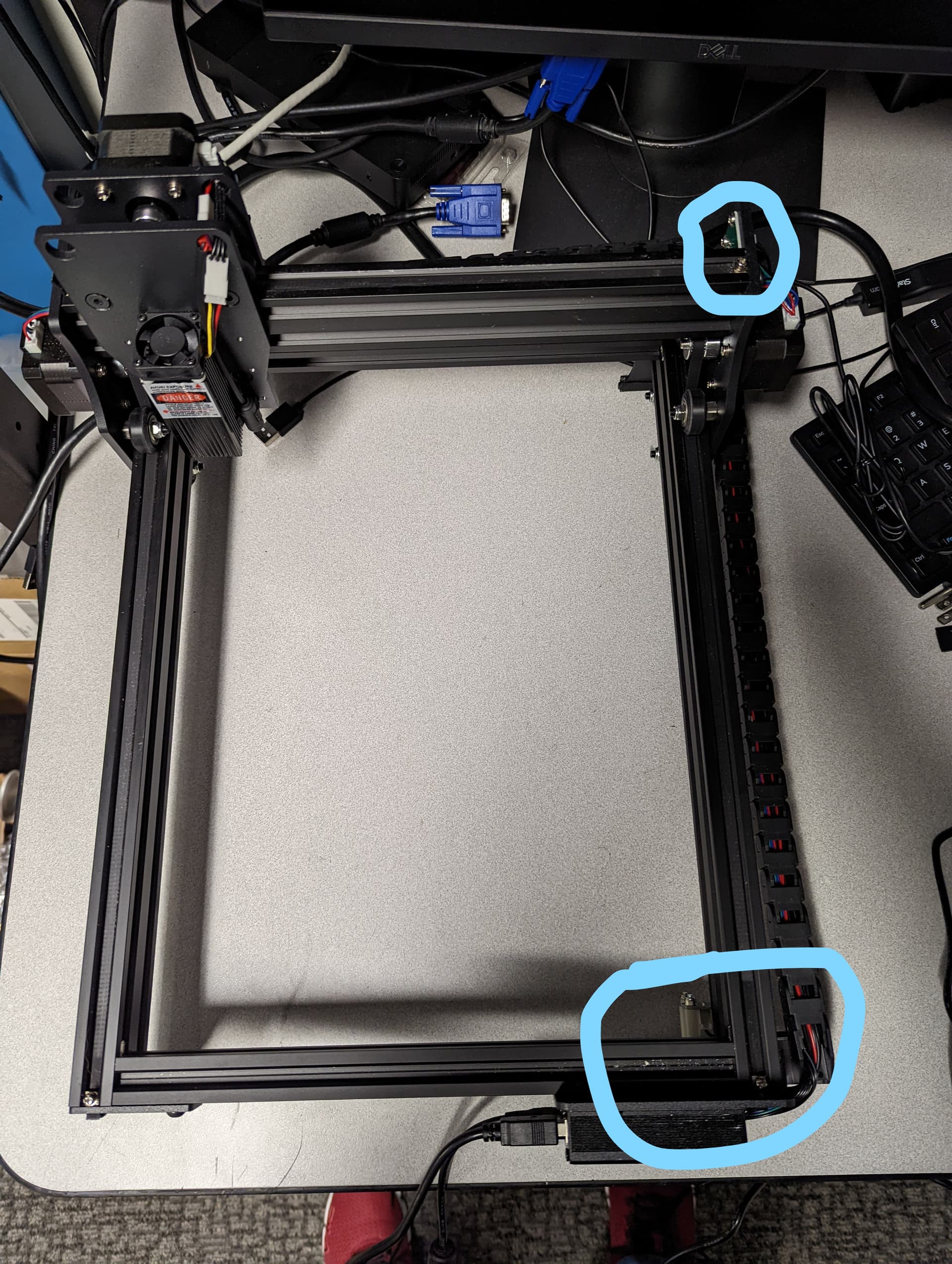
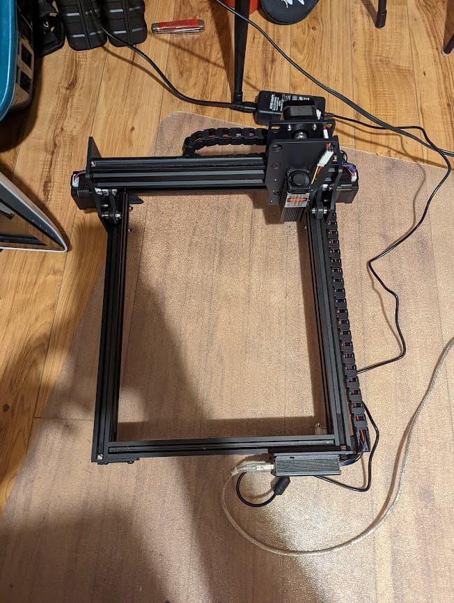
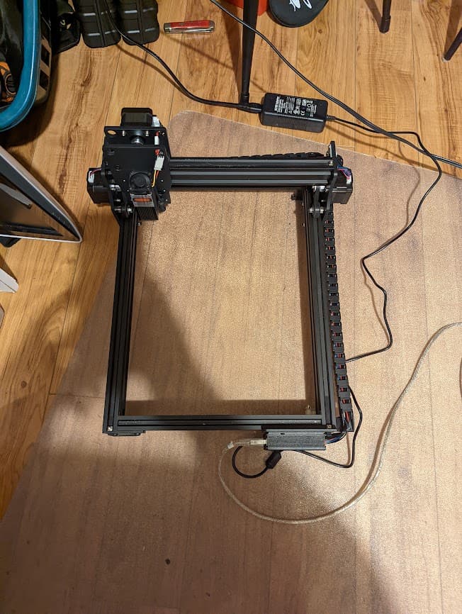
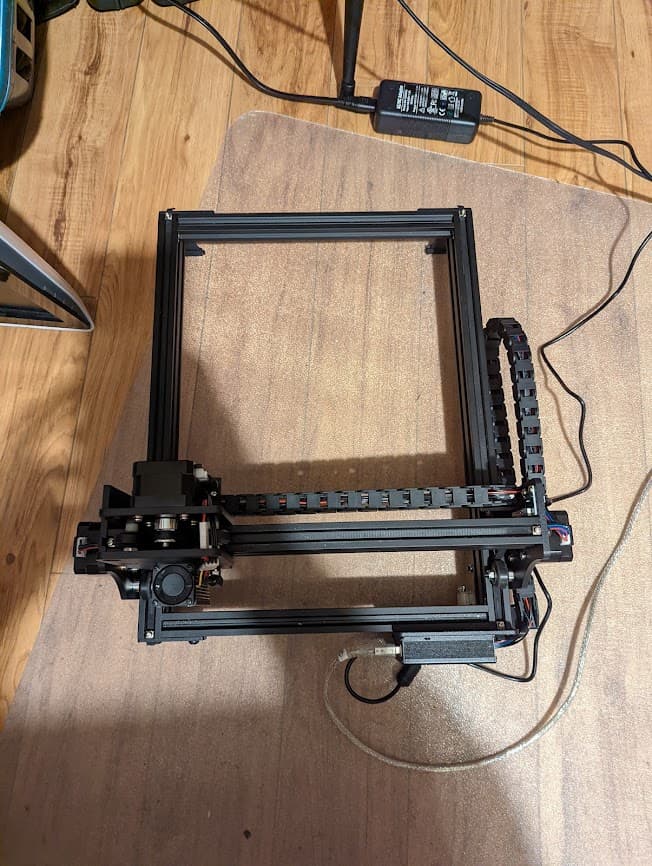
Hello everyone, I am having issues trying to figure out my homing switches. I have them circled to show their location. The laser is supposed to start in the back left corner then move to the front right, engage the switches, then go back to home. However, the X-Axis goes the wrong way, opposite of the switch. It will just keep trying to go left instead of right to engage the switch. Hopefully, this is an easy fix. I am new to laser engraving and was surprised I was able to get GRBL 1.1 on this. Any help will be appreciated.
In the meantime, I am using Lightburn with the “Current Position” option but would love to use the homing switches.
I’d like to hear some additional background on this.
What specific build of GRBL are you using? Where did you get it?
Has GRBL been pre-configured for your particular setup and/or what specific configurations were made to GRBL at compilation time?
This is a fairly elaborate homing process. How are you determining that this is the expected process? How does the laser know it’s in the back left corner to start? What’s been done in GRBL to have it “go back to home” after engaging the limit switches? The normal GRBL homing process stops at home.
I assume this is for the initial movement intended to go toward the limit switches. Please confirm.
In addition to the above questions can you run these commands in Console please and return results:
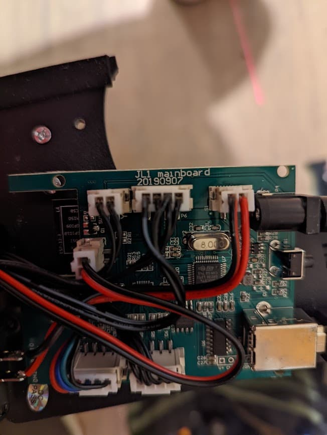
I believe it is version 1.1. The controller is a JL1 mainboard, a Chinese special. I was given an upgrade software that allows the laser to be upgraded to GRBL so you can use Lightburn instead of the horrible software that came with it.
2)I haven’t done any configuration for the setup, this is my first time using GRBL.
I haven’t determined this is the expected process. It is just what it did in the other software it came with. The laser would start at the opposite end of the switches then travel towards then, engage, then travel back to where the laser was when it first turned on.
I am assuming the initial movement is to start opposite of the switches and then travel towards them.
I couldn’t follow all of your responses and it’s uncertain based on what you provided if this will work as you expect.
So the change isn’t the addition of the homing switches? It’s the change in the firmware? And the firmware was provided by the manufacturer but isn’t functioning correctly?
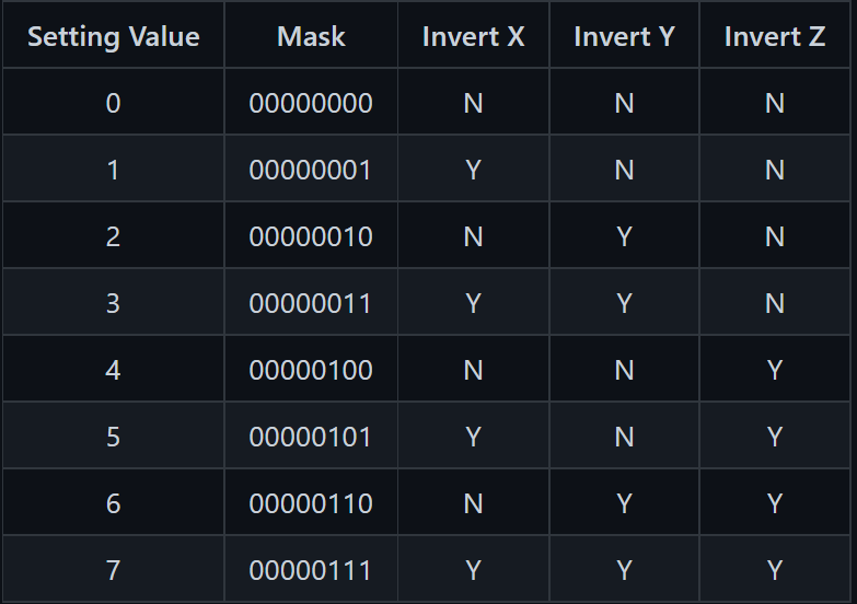
I’m certain I don’t understand the full context of this but let’s try to address the stated problem symptom. You’re saying the X-Axis is travelling away from the homing switch. In that case you’ll need to change the value of $23 which is currently set to 1.
The value is a mask. 1 means that X is in inverted state while Y and Z are not. To re-invert X while leaving Y and Z the same you need to set $23=0.
Before making any changes I highly suggest you take a backup of your GRBL configuration in Edit->Machine Settings. This way you can revert to starting state if required.
You can choose to make the changes in Machine Settings (it will show this as a toggle to invert X) or by simply entering $23=0 followed by enter in the Console window.
Sorry, I am not really sure about GRBL. The update I installed for was a different model of laser engraver but it used the same JL1 control board.
I made the change to line 23 line you suggested and now it goes the correct direction. But now there is a new problem. Here is a video link, maybe it’ll explain it better than me.
This information would have been useful. What laser was this intended for?
You’ll likely need to revisit all GRBL configuration if this is not designed for your laser system.
I’m guessing at least initially that the laser size is different between your laser and whatever the firmware was configured for. I assume it’s going to a different location beyond what you have the physical dimensions for.
These are the dimensions that are assumed for your laser in X,Y,Z respectively. Z is probably not relevant for you. But is your laser work size 370x360 mm? If not, these need to be adjusted.
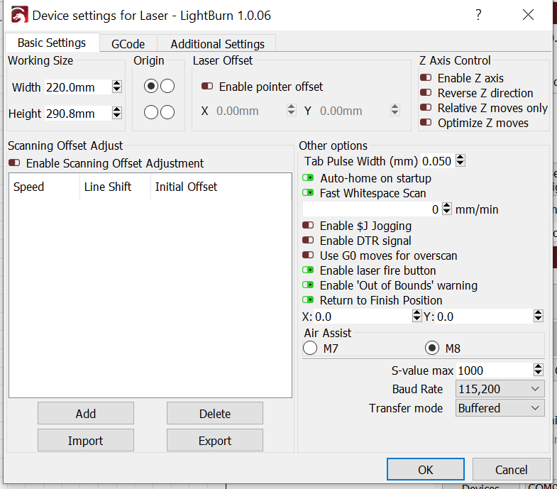
The laser it was designed for has the same exact laser as what I have. It’s a 7w laser. The work area for mine is 290x220mm so I will need to change that setting you mentioned. I guess I have alot of reading to do about GRBL. Hopefully it doesn’t become a nightmare. But with it talking to lightburn it should just be GRBL settings right?
I wonder if I change line 130 and 131 to the correct size, match it in device settings, and then put the laser origin in rear right if it’ll work fine.
Okay. Looks like you’re in a negative coordinate workspace. You’ll need to adjust for that.
Run these commands in Console:
$10=0
G10 L2 P1 X-220 Y-290
The G10 command creates a work offset shifting 0,0 to be at upper left.
$10=0 changes your controller to report work position based on the offset rather than machine position. You need this because otherwise the machine will report negative numbers to LightBurn.
If things go as expected you should have 0,0 in upper-left which is where it seems like origin is setup to be.
Confirm this by rehoming after setting the command. Then go around the corners. Upper left should be 0,0. Lower right should be 220,290.
The coordinates are right now. Upper left is 0,0 and bottom right is 220,290. When it turns on it does the auto homing thing and spits out this error in the console. The laser will then stay in the bottom right side. I can move the laser around with the move tab though. I can also click the “Go to Origin” and the laser will move back to 0,0 in the upper left corner.
ok
Homing
ok
ALARM:2
G-code motion target exceeds machine travel. Machine position safely retained. Alarm may be unlocked. (Right-click the ‘Devices’ button to reset the connection)
[MSG:Reset to continue]
ok
Grbl 1.1f [’$’ for help]
JL3_GRBL_v1.0
[MSG:’$H’|’$X’ to unlock]
[MSG:Caution: Unlocked]
ok
Can you describe what happens during the exact homing cycle? Normally it should
move quickly to the limit switches
bounce off
then approach the limit switches again slowly
hit the switches for the second time
pull away a set distance and stop
You indicated that prior to the firmware change that the laser would move back to origin position after hitting the switches. Does it still attempt to do that? If not, how does it differ from the steps listed above? When exactly does the console message appear within the steps listed?
Also, do all the jog controls work in the direction that you expect?
it make a long time i haven’t put my brain in the grbl firmware, this message is because this end switch configuration is for extems Security limits switch and not for home switch,
finaly you never find the home just a stop with alarm for the axis
this problems have take a lot of my time, but for this can works you must modify the firmware
My firmware is an modified hybrid grbl 0.9J/1.1f, on a arduino 328P chip
so you have 2 solution
N°1 : the better for working, you modify the firmware
N°2 : you accept to do the homing off the axis in 4 time "1/home X, 2/at the end clic stop ; 3/Home Y, 4/ at the end clic stop, you are at home, start to work
What you descirbed Berainib is exactly what happens. Here is a video showing what happens. After it pulls away from hitting the switches a second time it shows this in the console.
Console Error
ok
ALARM:2
G-code motion target exceeds machine travel. Machine position safely retained. Alarm may be unlocked. (Right-click the ‘Devices’ button to reset the connection)
[MSG:Reset to continue]
ok
Grbl 1.1f [‘$’ for help]
JL3_GRBL_v1.0
[MSG:‘$H’|‘$X’ to unlock]
[MSG:Caution: Unlocked]
ok
As @01power indicated the stops are not really being used as a traditional homing switch since we’ve defined this as the far corner from origin. This should be theoretically okay as there are other lasers that home away from origin.
I think what’s happening is that since you have soft limits currently enabled ($20=1) that at some point in the cycle it’s going past the defined 220x290.
There may be a few conditions as to why but not certain at this point.
Your homing pull-off $27=2 is insufficient and is sitting beyond the boundary of 220x290.
I’m not sure if origin after homing is established after the first contact with the limit switches or with the second. It’s possible that if it’s with the first contact that the second contact is exceeding work area.
I can think of a few remedies including turning off soft-limits or changing your origin position but let’s see what the current situation is first.
Can you run this immediately following a homing cycle?
Disable soft-limits - this will almost certainly work but removes one safeguard to prevent crashing in some scenarios. If you want to do this $20=0
Increase homing pull-off - this might work. Not sure. Right now the homing cycle has the head pulling away from the switches by 2 mm. Increasing this might relieve the issue. $27=3
Move origin to lower-right - I think this might work but can’t come up with a complete model in my mind of how to do this so don’t want to send you down this path.
Take a pick as to what you’d rather do. You may want to take a backup of your configuration in Machine Settings before playing around.
So I changed the settings around and it just wouldn’t work right. Glad I backed everything up like you mentioned. So once it does it’s homing thing and bounces off the switches I just click go to origin and it goes back to 0,0 and works perfectly.
Would it be easy to upgrade the laser? I want to be able to be able to cut 3mm wood and this one won’t do it.
Your current firmware will likely never go to origin on its own unless it’s been specifically compiled to do so. You don’t need the laser head at origin in either case. Jobs should run fine from your home location. I was just hoping to get rid of the ALARM message.
Are you saying that removal of Soft Limits didn’t resolve this? What exactly happened?
Should not be difficult. You’ll need to sort out a way to mount it if the current mounting holes don’t match. Pretty much every laser module depends on 3 connections (+,gnd,ttl/pwm) that are shared basically universally.
Make sure your system voltage matches the laser module voltage or have a way of sourcing the right voltage for the laser. I’m pretty sure your current setup is a 12V system. Most of the commonly available laser modules work at 12V but there are some designed for 24V.
Current is a concern with upgraded modules. Either make sure your power supply and controller are capable of safely providing the higher current draw or assume you’ll have a dedicated power supply for the laser module.