Homing fail/could not find limit switch

Update 2 - Double checking showed that $J jogging was enabled in the Device Settings. Disabled it and the jogging works fine.

Still have the negative Get Position issue to work thru… Pretty certain that’s why I can’t use the Find Center tool… But it’s progress at least.

Thanks will try this tomorrow.

So since that post I have got the laser to move but when I click home only the z axis moves and it doesn’t go all the way to the limit switch.

Which is why homing fails: the Z axis doesn’t finish homing.

GRBL $132=90.000 defines the length of the Z axis, so the homing will fail after 135=1.5×90 mm.

  • Is $132 correct?
  • Does the Z axis travel about 135 mm without hitting the switch?

Edit: Also, $102=199.100 indicates the Z axis has the same step/mm value as the other axes. This seems unusual, as the Z axis generally has different mechanics. Have you calibrated the Z axis?

no I haven’t calibrated the z axis

So $132 is equal to 90. but I measured the z axis to the switch and it’s 517mm.

So under calibrate axis do I put 517mm for actual distance and requesting distance?

Let GRBL know about how long the Z axis is by setting $132=500. That way, it can move about the right distance and you can fine-tune it later.

The Z axis speed and acceleration values may be too high. If it doesn’t move smoothly or makes horrible noises, back those off by a factor of ten. It’ll be lethargic, but at least you can proceed.

Then follow the process you used to calibrate the X and Y axes:

I do it on hard mode, but that’s just me:

  • From stepper driver hardware, get step/rev value
  • From axis hardware, get mm/rev
  • Calculate mm/step = (step/rev) / (mm/rev)

For example, if the stepper driver is set to 6400 step/rev and turning the motor one revolution moves the Z axis 4 mm, then you’d get 1600 step/mm = (6400 step/rev) / (4 mm/rev).

With that in hand, you can fine-tune the value using LightBurn’s calibration routine, which will take care of anomalies like getting a mis-cut leadscrew from a random eBay seller. Being me, I do it by direct measurement & correction:

A few iterations should settle it down pretty quickly.

When you have the axis length pretty close and it’s moving correctly, it should home correctly. When it does that, you can fine-tune $132 to match the actual travel.

Then you can adjust the speed and acceleration upward to more useful values.

1 Like

Excellent! I think you have this on track.

The amount that GRBL uses to define homing is 1.5 times max travel. 1.5 times 90 is 135 so it would have thrown the error if it was further than 135mm from the limit switch.

Setting that to 500 looks like a solid fix. Travel geometry and calibration should be confirmed after this is taken care of.

Thanks @ednisley

This information fixed a homing issue I had with the Z axis. $132 was set to 0 and I could not figure it out till I read this post. My Z axis is just a spare motor and a limit switch because my board is a 3 axis board on a 2 axis machine. Thanks so much.

I just want to make sure I got the correct height for my z axis. I measured from the top of my board to the limit switch. Is this the correct way to get the height of my z axis?

When I started laser today it homed to the front left corner, but i had manually moved the z axis to the limit switch. Is there a video showing how to calibrate the axis?

Ok, so I have done something wrong when I was trying to calibrate the x axis. I could not move the laser from the calibrate tab so I followed the instructions that sais to jog it. So i jogged it over 40mm and measured and the first actual measurement was like 2mm. I did it again and the actual measurement was 7.8mm. I rehomed after each time and it homed perfect. I did it a third time and the measurement was like 70mm. and after this it would not home back to the x axis. the y and z homed fine. How do I correct this?

Please capture the Move window in LightBurn where the Jog controls are using a screen capture tool.

It’s possible that the lack of repeatability when jogging is speed or acceleration related.

No… I’m not even sure the 517 is correct.

Please measure the amount of travel that is available for the Z-Axis to move. It may be difficult to measure if the lead-screw is hiding in the mechanism. The number that you want is the Max Travel.

Perhaps this will help:
grbl/doc/markdown/settings.md at master · gnea/grbl · GitHub

Calibration is about changing the steps per mm.

If the Z-Axis is a lead screw and the other two axes are controlled by belts this will make the calibration very different.

Ok, so I can see the screw rod that z axis is on and it measures about 18.75inches or 476mm. The X and Y axis are belt controlled. So how do I calibrate these if it is different?

image

You may only have half that Lead-screw length available to you depending on how the Z axis is supported.

The first thing I’d recommend is reducing the speed and acceleration of the Z axis. We’ll start with the Motion Settings:

In the Console window in LightBurn please type the following in preparation for calibration:
$112=1000
$122=100
Press Enter after each command. These aren’t written in stone - they’re an educated guess at best.

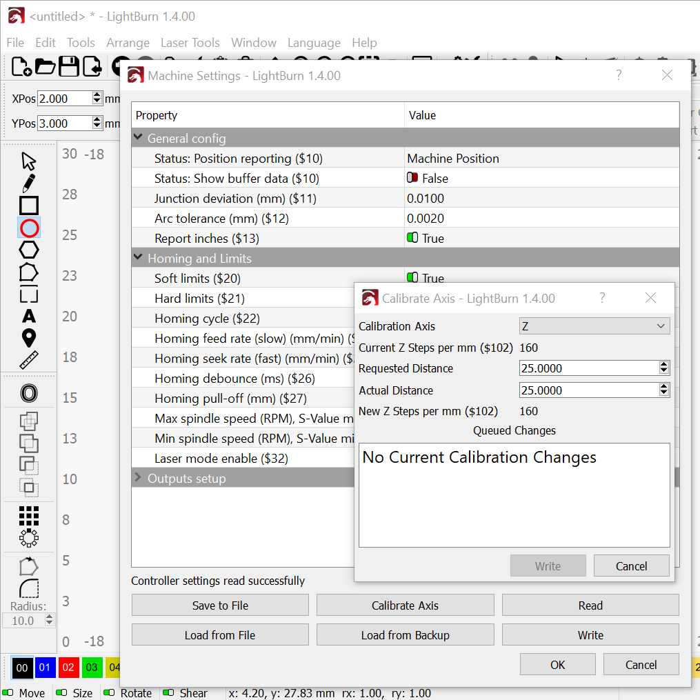
Calibration for the Z-axis (steps per mm) is shown for $102.

Would you be willing to fasten a scribe or an awl to the engrave head that it points horizontally? It doesn’t have to be perfect or dead level, It just needs to hold its position to make half a dozen marks. You’ll get great calibration data doing this with a sharp marking tool - it will outperform a felt pen by a considerable amount. It’s also much safer than turning the laser sideways. :slight_smile:

In the jog window in LightBurn, lower the engrave head and confirm that the up-down arrows are behaving correctly. Make a mark on something cheap and recyclable with the scribe attached to the engrave head. I’d use an aluminum can or coffee can, a piece of scrap is fine as long as it’s repeatable.

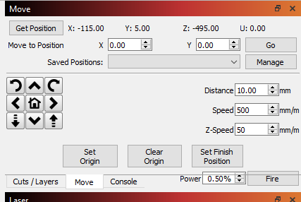
In the Move window set the distance to Jog upward 100mm.

After that one upward Jog command, scribe the selected object again.

Measure the distance between the two scribe lines (a Vernier or Dial Caliper would be a good choice).

If there is a substantial difference between the 100 mm Jog distance and the distance between the scribe-lines we can freehand the first adjustment by changing the ratio in $102.

You are also welcome to adjust this in the Machine Settings window in LightBurn:

Click Edit, click Machine Settings, click Calibrate Axis, and select Z for the Calibration Axis in the top box of the Calibrate Axis window.

Enter the Requested Distance (100mm) and the Actual (Measured) distance then press the Write button.

I would expect a first pass to be about 95% accurate.

Jog the engrave head back down - by the measured amount from last time. The measured amount will be closer to much we want the engraver to move now that the calibration is closer.

Mark the object with the scribe again, Jog upward 100mm in the move window and mark it again. Repeat this calibration process until you can no longer detect a difference between the Requested Distance of 100mm and the Measured / Actual distance.

Post measurements and observations as you go. It’ll be interesting for us to see how different the calibration is. :slight_smile:

What or where is the stepper driver hardware

Without pictures of your machine, it’s hard to be specific. From your profile, I assume it looks something like this:

(That is a big machine!)

And that the controller looks like this:

The motors are wired (plugged into) to the stepper drivers and each stepper driver has:

  • A pin header selecting the number of steps per revolution
  • A trimpot controlling the motor current

You can compare the jumper positions on the pin header to the controller doc to figure out the step/rev setting for each motor; the X and Y will (probably) be the same and the Z will (probably) be different.