With a little CAD training, you’d probably approach this the way one would in a CAD package.
NOTE: This is the slow brute-force way. There are faster ways through this.
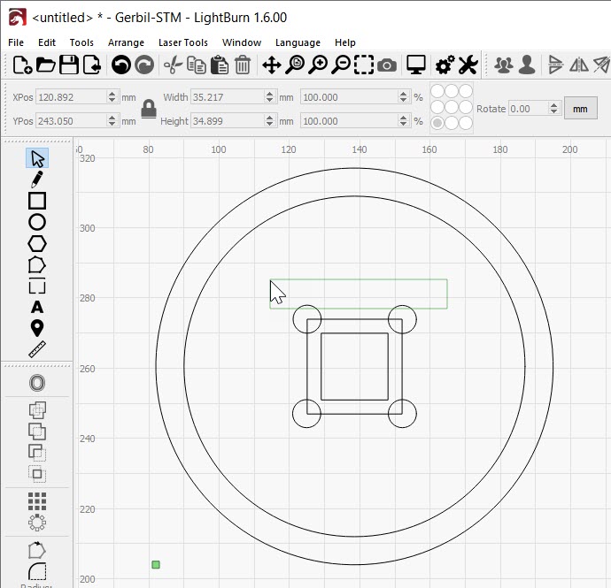
Measure the ID and the OD of the 4 arcs and draw two circles. Drawing one, and offsetting it to get the second one might be fast.
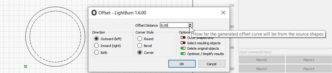
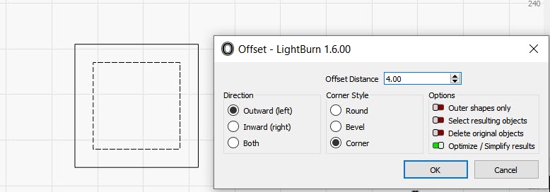
Draw the second circle, offset from the first circle. I picked 8mm (pretty close to 5/16").
Turn off “Delete original objects” to keep both circles.
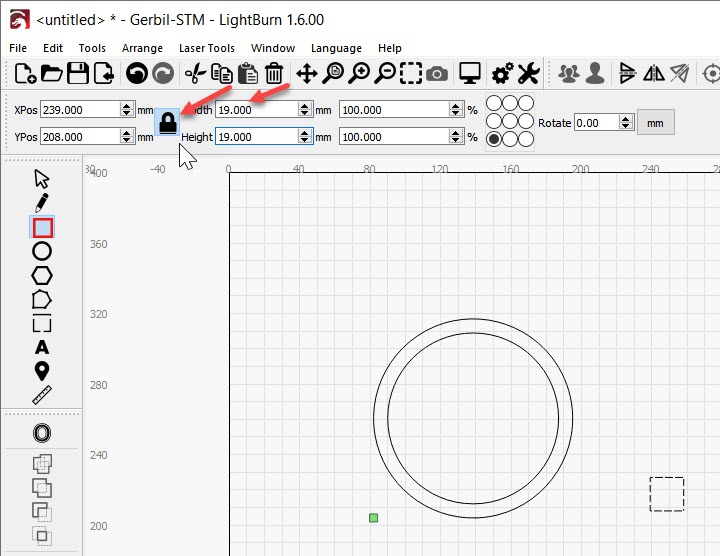
Then, measure the distance between the ends of the arcs. I’m going to pick 19mm (pretty close to 3/4")
The Array tool would be faster for this, but I’ll do this by drawing a square and copying the small circle into the corners of it. You can also draw one slot and apply the array tool to that… or the mirror tool. There are many faster ways through.
Grab the rectangle tool on the Left Bar, Hold the Shift key, and it forces a square when you draw with it. Put it anywhere in the workspace.
Click the Lock button to lock the ‘aspect ratio’ and change one of the numbers to 19mm (or whatever you measured).
I’m going to offset the square outward (half of 8mm… 4mm) so the circles line up with the edges of the 19mm square.
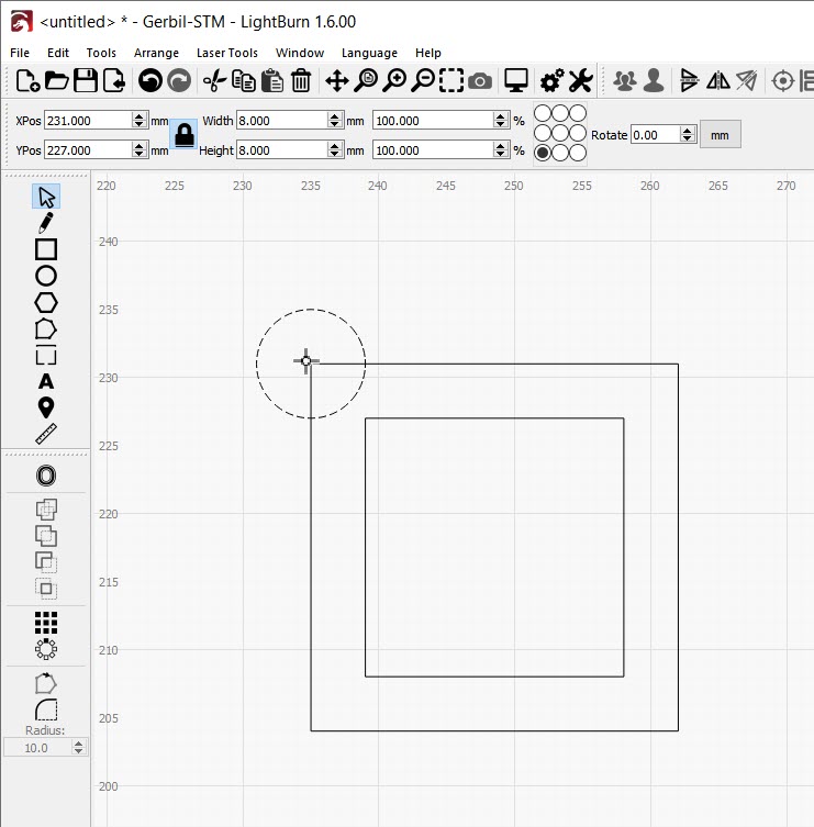
Click ok. and Draw circles from the corners of the new square.
Click the Oval tool, hold Shift to make the Oval tool make a circle. If it’s messed up, just change the numbers in the box.
Change the circle to 8mm Width & Height then grab the center dot of the selection grid and drag it over to the corner of the outer square. The Pointer will change and give you the crosshairs when you’re close and the center of the circle wants to snap to the corner of the square.
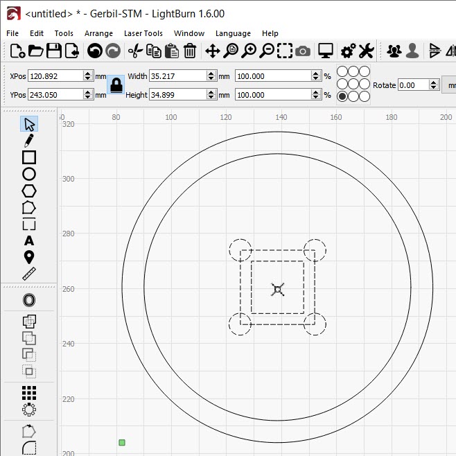
Copy that circle into the other corners:
Then grab that whole mess and drag it into the middle of the other two circles. The cursor should tell you when it’s set correctly.
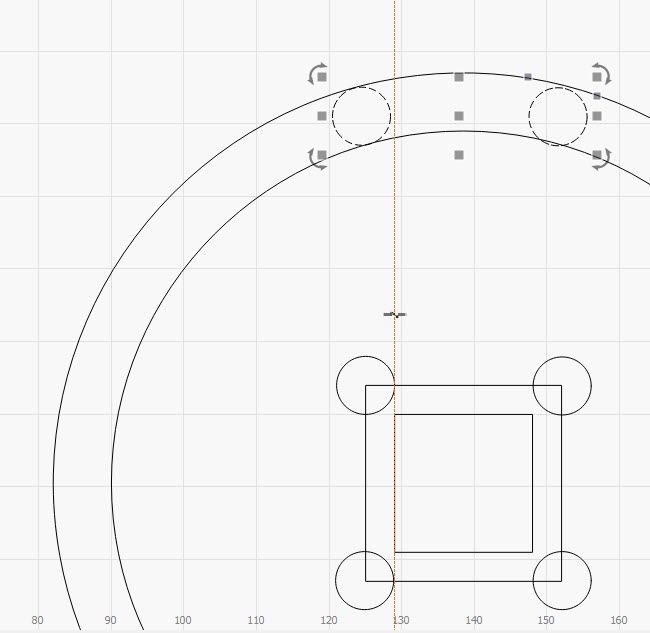
Grab a pair of circles, copy them and paste them into the outer circles.
Drag the selection tool from right to left and just barely touch the circles.
This is tougher than it looks… Roll the mouse over to the left side of the work area until the cursor changes as shown, click to drag the red guideline over to the inner square 
Click one of the small circles, hold shift and click the other one… Ctrl C to Copy, Ctrl V to Paste and drag the pasted pair into place. Zoom way in to get them to snap into place correctly.
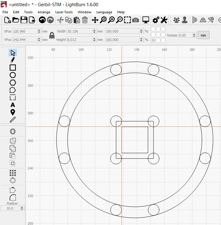
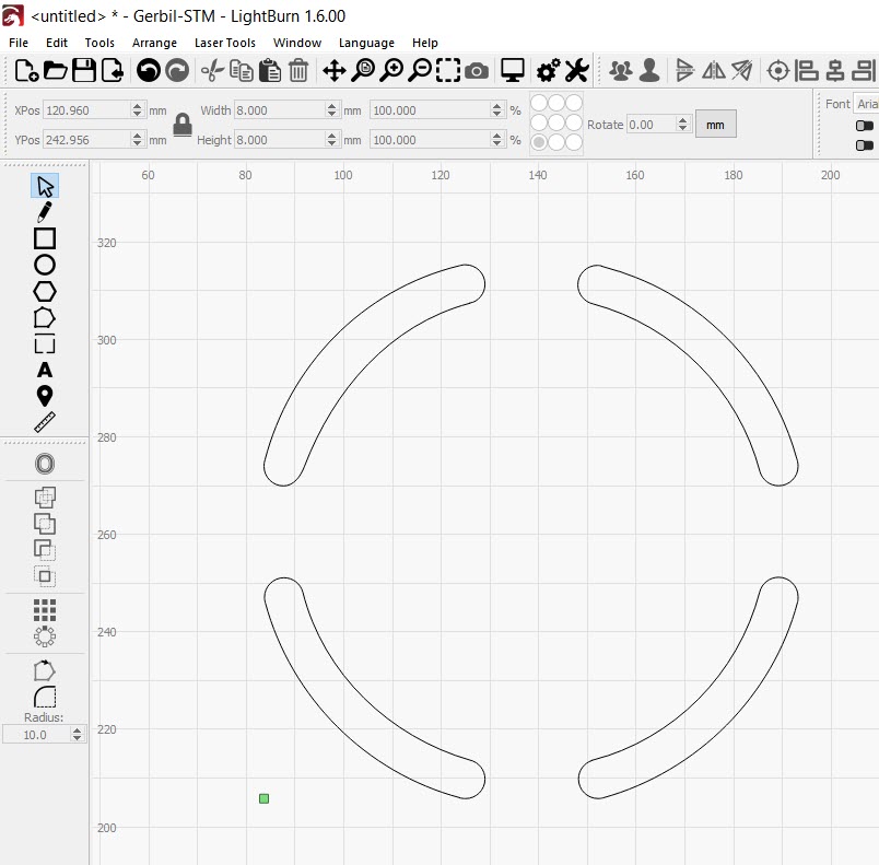
Grab the Red Guideline tool off the top edge of the work space and copy the two circles on the right, over to the the right…
Continue copying the circles to the outside.
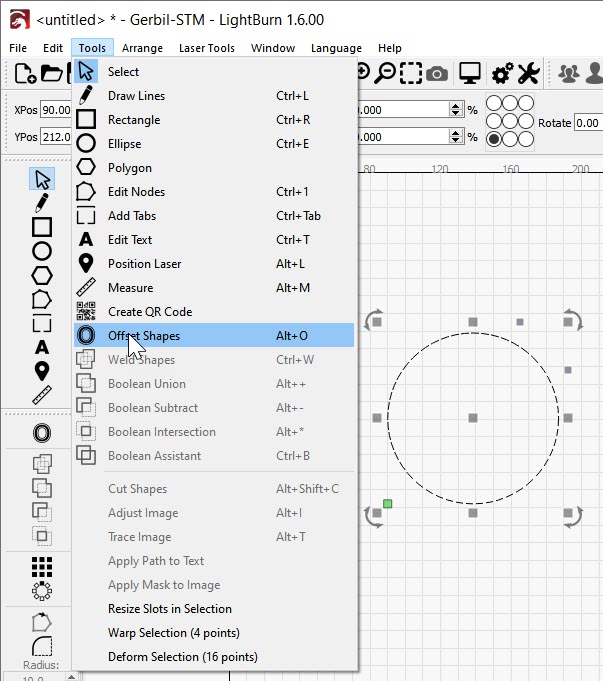
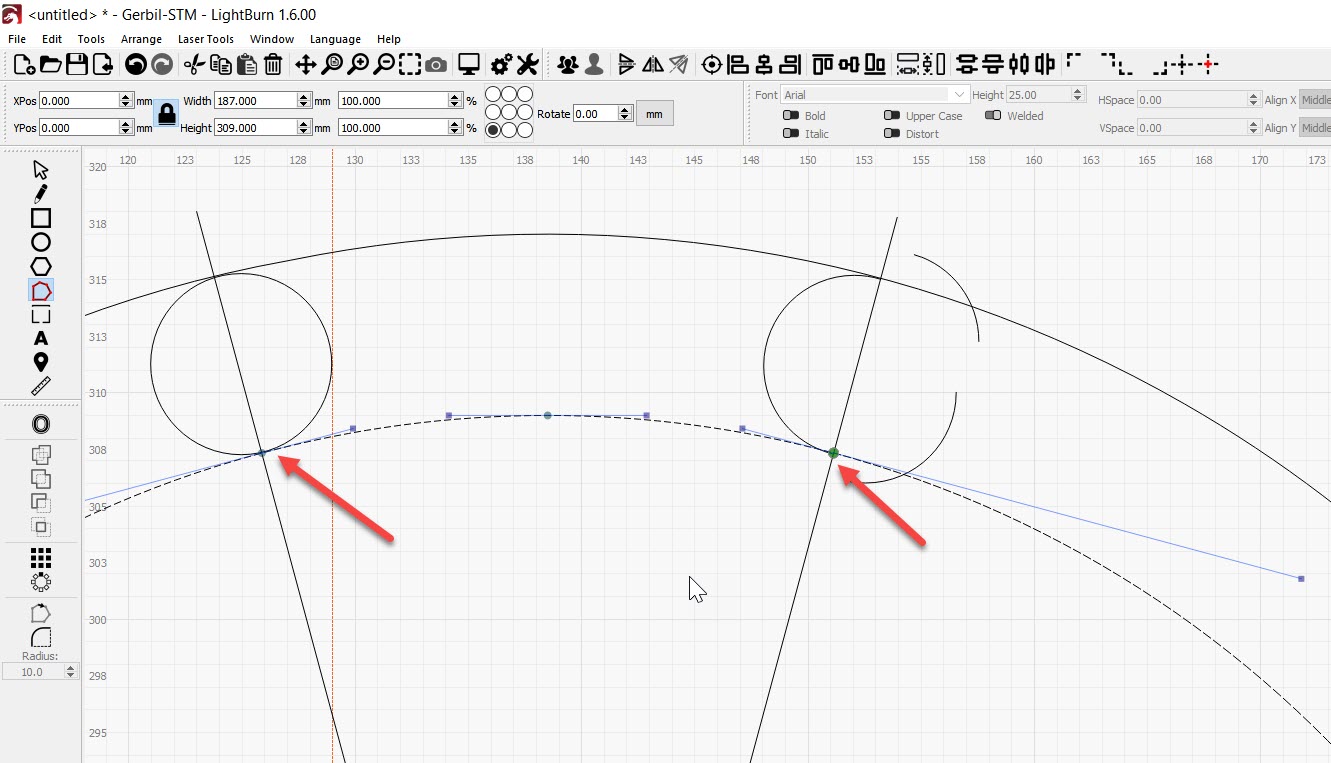
In LightBurn, select Edit, then Convert to path and change all the circles (shapes) into circular paths (so we can use the Node editor).
Click the Edit Nodes icon on the tool bar on the Left. Hold Ctrl B and click where you want to break your circle.
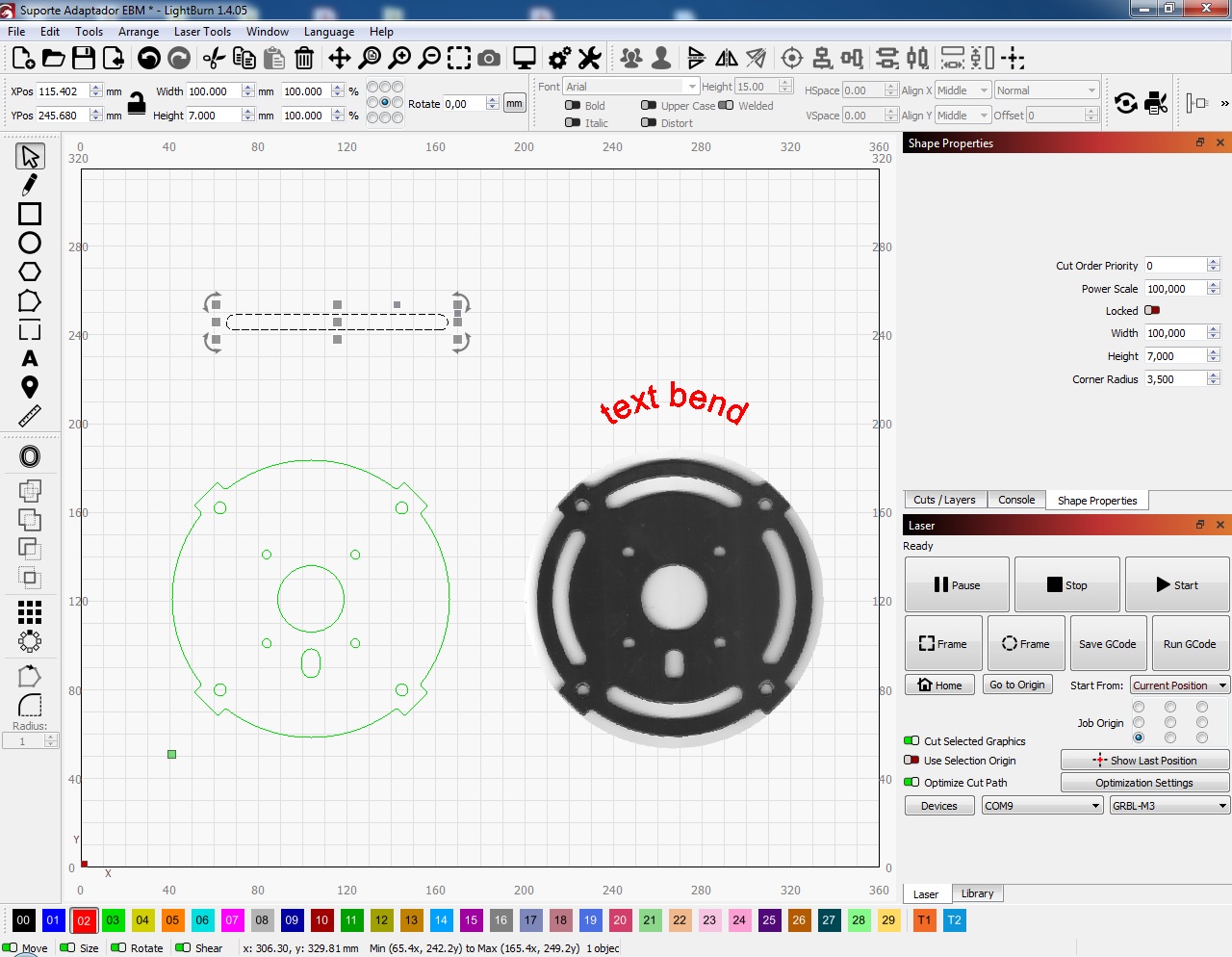
Those Diagonal lines weren’t useful… I sketched them in when I was trying something else.
Continue to break all the Circular paths… and drag the junk out of the way.
Delete the junk you don’t need.
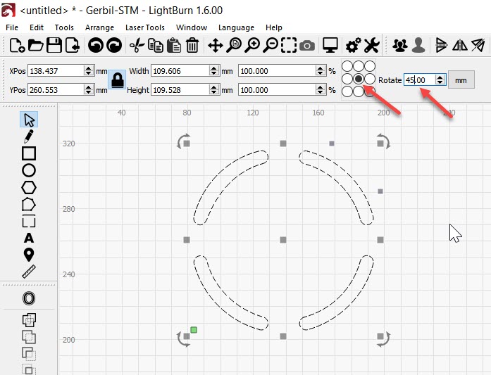
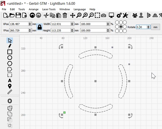
Finally, select what’s left, choose the middle dot for handling the group of shapes, click in the rotate square and rotate the selection 45 degrees.
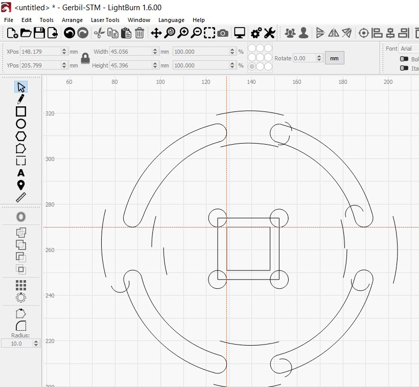
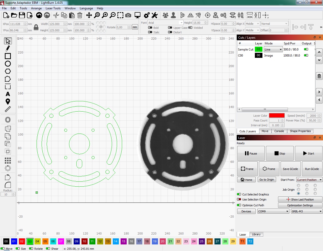
I think you want this when it’s done.
I’ll write up a faster way if you tell me the sizes. A hand drawn sketch is fine.
Here’s a handy video about Node Editing.