I am still new to Lightburn and struggling to get the following to work.
EDIT:My laser is a TTP Laser String Ray with Ruida 6445G controller
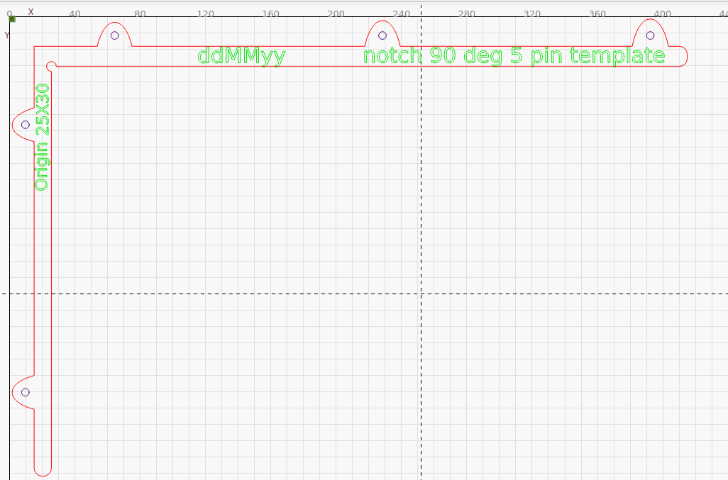
I made a fixture in MDF from my Shapeoko for laser engraving.
I made a crosshairs target in the upper right corner that I could hover the laser red dot over (providing the red dot and laser are in perfect alignment) and set the origin point.
I exported this template from Carbide Create and an SVG file
Imported SVG template file into Lightburn
Turned the output off
Used the squares to type my text within
What I expected to happen is the green dot origin point would go to the cross hairs and start the job from there so I would have a 1 to 1 alignment between the fixture and my file in LightBurn.
However it is still always choosing the upper back right corner of the machine to start from so everything is out of alignment.
How can I set the cross hairs in my template (attached) so that the green dot start point is dead center on the crosshairs on the fixture that this same template was used to make? Does the software not work like this ?
If I understand what you`re after I believe the upper back right corner is defined in Ruida controller, (Red square) is machine origin. The green square is job origin.
After reading this docand understanding how the coordinate system and origin works on your laser you can alter to your preferences.
Put the laser head over the crosshairs and tried the following
Put it on user origin - pressed origin button on laser - did not frame correctly
Put it on current position - did not press origin on laser and sent file to laser from LB - did not work it is framing wrong
Put it on current position , pressed origin button on laser - did not frame correctly
*in both instances I tried clicking go to origin and the head hit the limit switches and froze the machine, I had to reboot it, Home also resulted in the same.
The controller is defined correctly with an area of 1300mm x 900mm
Look at your device settings and ensure the dot selected is the corner the machine goes to when it powers up… this is home or 0, 0.
If this is incorrect, it will never behave…
The other areas are the Job origin and the Start from.
If it’s setup correctly, it should never collide with something… I think it’s pretty clear there is something amiss in the settings for the device or Lightburn.
My guess, if this is new, it’s the Lightburn configuration you’re having issues with.
What corner does it home? Does the console have 0, 0 for it’s location?
Which corner is set in the device settings within Lightburn?
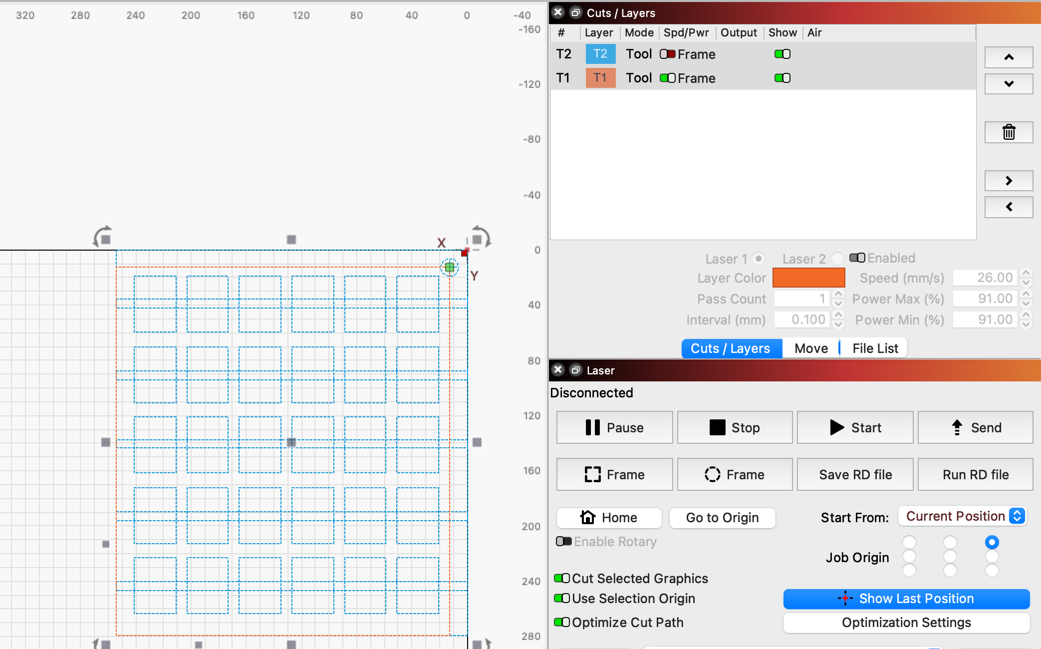
When using User Origin or Current Position, you must also select a Job Origin location, which is either on the center or at a point along the perimeter of the graphics in your workspace (or selection, when using Cut Selected Graphics).
You could select the center origin if the crosshair were perfectly centered in your fixture, but since it’s off to the top right you’ll need to select top right as your origin point, and create a new rectangle whose top right corner is centered on the center of the crosshair, and use that — and not the original crosshair or outer rectangle — for orienting output and framing.
I’ve edited your file to show what I mean. I set the new rectangle to the T1 Tool layer, and everything else to the T2 Tool Layer. I toggled the Frame option off for for the T2 layer, meaning it will no longer be used for calculating origin.
Only the rectangle on the T1 Tool layer will be used for calculating origin, moving the origin point (and green square) to the center of the crosshair.
Maybe you might want to take a look at this thread as it might help.
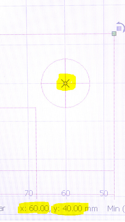
From what I understand you’re trying to adapt the laser to the jig, but I think it’s easier if you adapt the jig to the laser, i.e. if you take your jig and set the target in this example at X=60 Y=40 add another target also integer to make it easier,
and fix the jig I think you’ll get what you want.
.
For repeatability, you can have a base that is fixed to the laser or rests on reference points (for example, a right-angled piece) with two shafts at the points of the targets and then just place all the jigs you make on top of that and everything will be fine.
You can also add 2 more targets to validate the alignment.
In the future, you can repeat the same steps for a similar jig, or just create a rectangular jig, and align to a corner of the jig instead of the crosshair. Then you’ll only need to create a rectangle set to a Tool layer that is the size of the jig.
I was thinking if I could get the red dot on the crosshairs then I would be perfectly aligned for the job by using the same template I used for my CNC, exporting it as an SVG and importing it into Lightburn.
I have a large laser so my work table is 51"x 36" but that table is not stationary its a honeycomb bed that sits on rails. This is why I was trying to do it the way I was as I figured if I can create a focus point on the fixture I will have perfect alignment every time. Regardless if the table is a little off.
Maybe there is a trick here or the experience I lack is showing
IIRC, that’s @jkwilborn (who’s faster on the Reply button than I am).
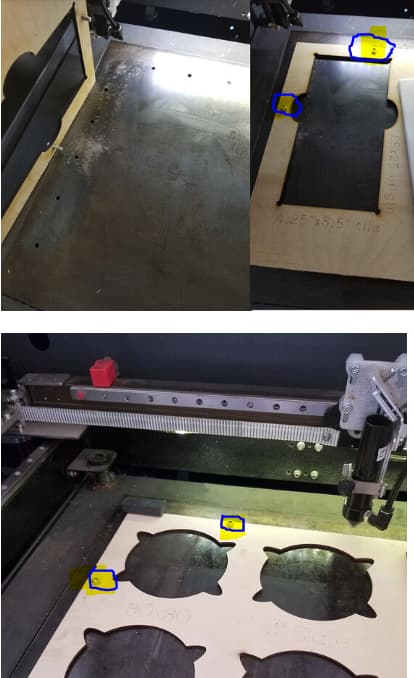
I generally use fixtures with targets aligning a tool-layer template with Print-and-Cut. That eliminates the need for the screws: no matter where the fixture sits, the template is exactly aligned with it:
I hold the fixture in place with tape or some such, which is permanent enough for a day in the Basement Shop. If I were in production, screws would make more sense.
I have no visible led on my machine… pulled it off after about a week… Change lenses, have to change/adjust the pointer… got tired of dragging it around and not using it… ripped it off…
I looked into an SPI tube, that has an internal combiner/led source… Russ advised against it…