Ikier K1 and Atezr L2 "modes". Anybody know what they affect?

I tried reaching out to Ikier and got the predictably useless response … “here’s a link to the user manual”. Basically the same response I got when pressing for a firmware that addresses the extension kit. I’m tired of bouncing emails back and forth with people that don’t speak English (nor I, Chinese) and clearly aren’t technically informed. Took me a week of back-n-forth to get the most basic “change $131 to enable extension” sort of response. Thanks. I got that on my own. Machine still won’t use the full bed offline. Not that I care, but it still ain’t “right”.

ANYway,

These machines have three “modes” available thru the offline/integrated touchscreen. “Fine”, “Standard”, and “Fast”

Per the manual, this is all that’s said (verbatim)…
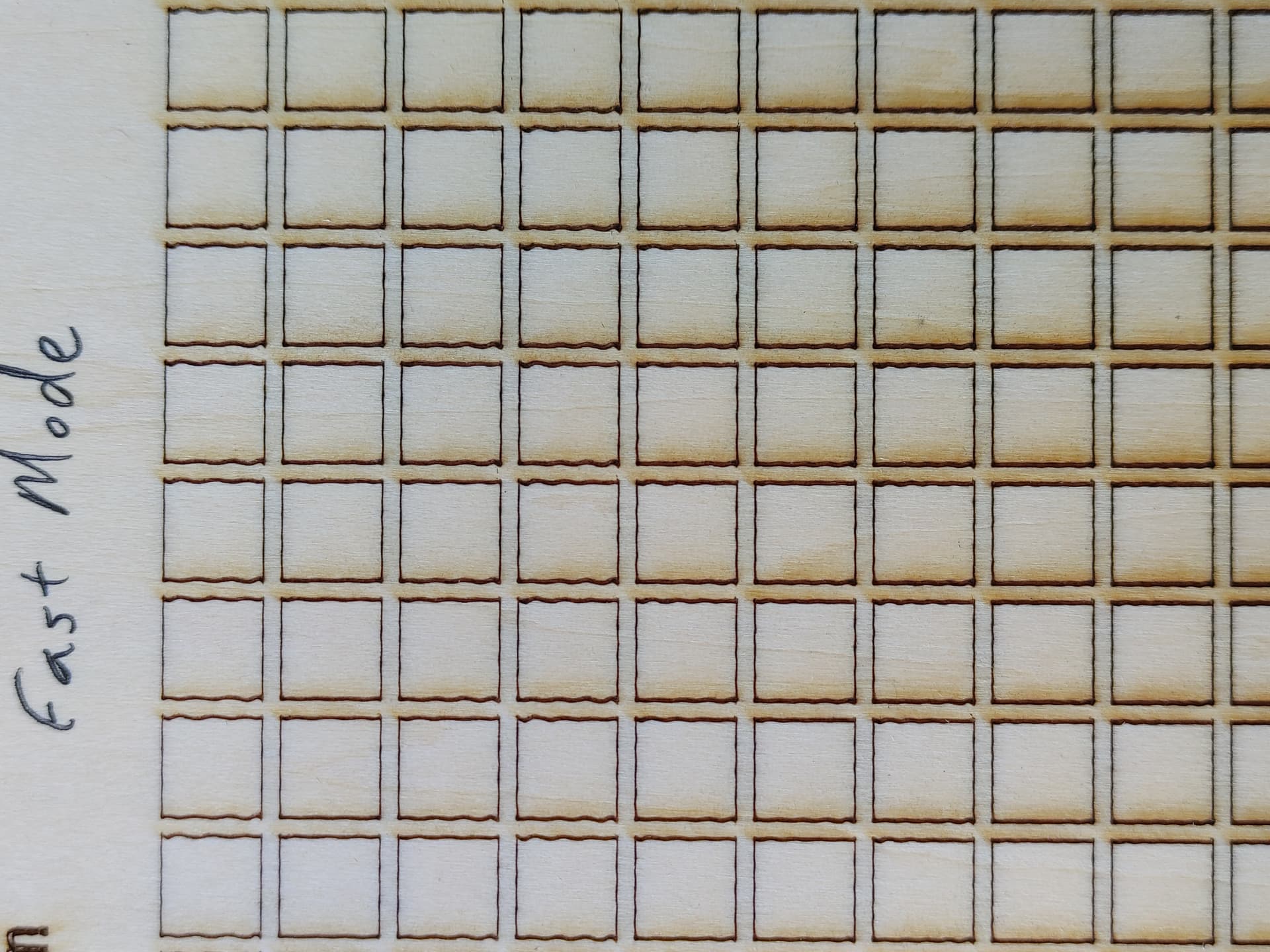
“Fast - Highest speed, normal engraving accuracy”
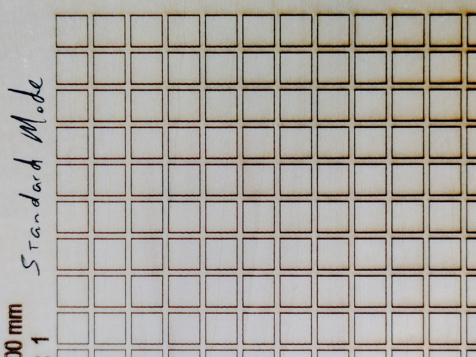
“Standard - A precision-speed-balanced mode which can be used as a general mode (factory default mode)”
“Fine - best accuracy, slower speed”

OK. Sensible enough, but I want specifics.

If anybody out there knows, I’d like to know…

Does switching these modes somehow affect external machine control (Lightburn) or is it limited to offline/thumb drive control only?

It would seem to be altering machine parameters (interrogating and rewriting gcode prior to execution seems unlikely), but is it restricted to volatile settings or a table-switching feature in the firmware or what?

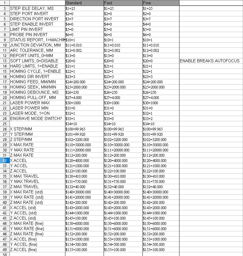
What exactly is is changing? Max speed and Accel seem obvious, but what about stepper motor parameters and other things?

Up to now I’ve only used “standard” mode.

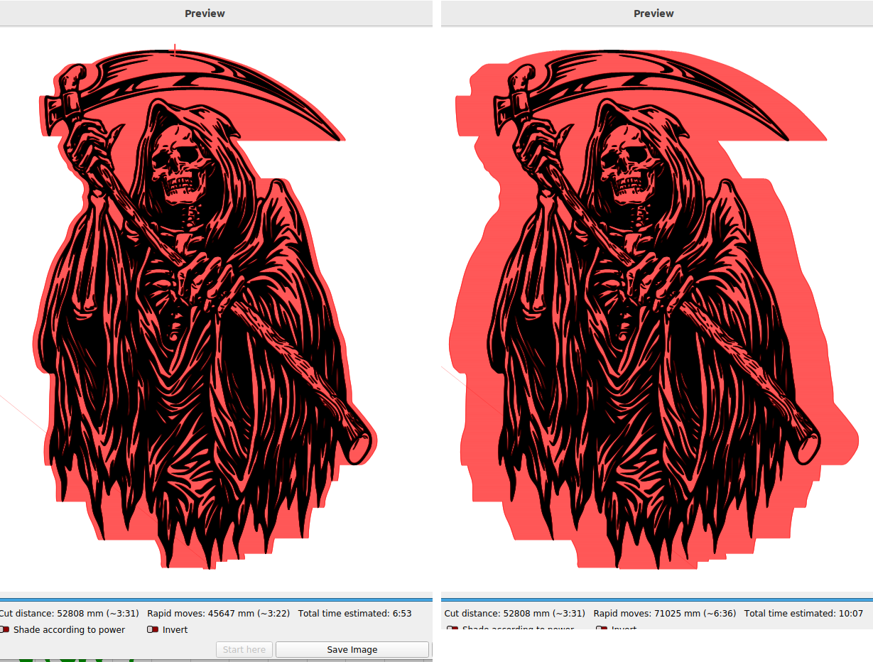
I hope to investigate a bit this weekend by changing modes and comparing $$ reporting. Maybe try running the same file thru LB using the three different modes to see if I can tell a difference.

If anybody can shed any light on this, I’d appreciate it.

Also thoughts on an enlightening test procedure and/or files?

After a bit of testing, I have determined the following…

$$ after mode change & engraver reboot shows no difference.
Mode absolutely affects Lightburn control.
Accel and Max speeds are absolutely affected.
Fine appears to limit max speed to approx 6000mm/min. Both Axes.
Standard appears to limit max speed to approx 15000mm/min. Both Axes.

I don’t know how to measure Accel, but the differences are significant. I drew a simple rectangle at the max bed size (410x750), set the layer speed in LB to 6000 so all 3 modes would have the same max speed (in theory), and noted the time it took to run the full path from the console. 26 sec for fine, 25 sec for std, & 24 sec for fast. When I bump the speed to 15000, the difference is 2 sec between fast and std (10 vs 12 sec). Not super accurate. I know. But more consistent than I could manage with a stopwatch.

I didn’t bother trying any faster max speeds to see what the Fast limits are. I assume they match the $$ values of 50000(X) & 20000(Y) I really can’t imagine myself using it above 20k, so it’s kinda moot.

I’m not quite sure how I should proceed from that. Guess I’ll run some geometric test cards to see if any of the settings are objectionable and go from there. Maybe tweak the speed and accel myself if necessary.

I actually think this is a pretty neat feature (I’ve never seen this in diode lasers before, myself) - but this does exist in the machining world (as a CNC machinist). Fanuc/Haas/Brother/etc controllers all have features in gcode that allow for this sort of thing. For instance, if you’re machining a boss that has a very high tolerance, you can switch on high precision mode for just those features, then go back to a lower precision mode for general work (at a higher speed, and thus lower cycle time). Neat.

Ditto…


The CNC machines we used on metal could enable a fast mode, that only moved between cuts faster, but the actual cut was whatever was specified.

My experience with metal cnc, or any machining operation, is a specific speed/feed for a specific type of material. You couldn’t get away making it faster by doubling both the speed/feeds…

It’s always nice when you actually post the link, so we can look at the manual. We might read something differently… I haven’t looked at it and I’d like too. :pray:


How you test these will change the results. Always specify the size of the square you are testing. A smaller square may not allow the head to reach the specified speeds…

With a scan/fill it has to slow down, change directions and speed back up, all with the laser turned off, this is overscan…

If you really want to know, you can video the head with some type mm/inch scale. Look at it frame by frame, knowing the frames/s, see how far it moves between frames.

Acceleration has a big hit on performance… Vector speeds are reached quicker and scanning operations have less overscan, so spend more time working than the slowing, a direction change and speeding up…

Using preview, which I suggest you use before any job, you can see what Lightburn thinks is the overscan from the show transversal moves option.

Values used for this are read from the controller, although you might have to go to Edit → Device Settings → Additional Settings, along with a read of the controller to see what they are exactly…

This is from my Ruida and shows the effect of acceleration between 40000mm/s^2 and 6000mm/s^2 with a scanned (filled) image. The overscan is red… also note the difference in time to complete the job.

This looks like a really fast machine… Really curious how it will perform…

Do they say much about the power bar on the front of the laser module?

:smile_cat:

K1 Pro User Manual

It definitely moves fast when asked, but I haven’t yet tested limits to see what’s actually useable. With 22-ish watts available, the highest speeds don’t seem useful, but if the mechanicals are solid enough, the accelerations may well be. Still only working with short NEMA 17 steppers and GT2 belts, so torque is limited and belt deflection/bounce is a major factor. There is a 48W model, tho it it’s obviously heavier, so it could do work at higher sustained speeds, the accel values would have to be tempered somewhat with it. They are also advertising an available 20W 1064nm module with remote source, fiber transmission, and (presumably light-weight) gantry-mounted collimator. If it’s real, that could be a game-changer for certain jobs. US$1200, though…

Unfortunately, the modified parameters don’r show within console ($$), machine settings, or device settings(additional). At least I couldn’t get them to show. Tried various iterations of reboots and refreshes. I’d love to know the specific adjustments they’re making.

I’ve not seen anything remotely technical or informative about the power bar. It does work but seems more flash and novelty than anything. At 2% power, 1 LED is red, 1 is sorta violet, and the rest are blue. There are 12 LEDs, so I’d expect 1 red led to indicate approx 8% power output with the violet representing maybe 4%, so having 1 red and 1 violet would seem to be about 12%… The math is dumb. (10 LEDs would be more intuitive) and it clearly isn’t converting output power to a visual medium that’s easy to interpret with useful accuracy. It’s a quick and rough confirmation of output at best.

This has the specifications on the NEMA17 and NEMA24 motors… maybe the data would be useful to you. It’s a pdf, so remove the .txt extension.

Data-Sheet-Stepper-Motor-Support.pdf.txt (839.0 KB)

I was surprised how many gantry lasers have fiber to deliver the beam to the head… I would think they would want an beam expander, not collimated, but I don’t know…

That’s pretty potent at that frequency. Most of them (without remote) are about 2W…

:smile_cat:

I honestly don’t know what the head on that 1064 is doing. I’m REALLY new laser and just assumed it was a collimator.

Advertised 0.03 x 0.06 spot size

Ikier 1064

They claim it’s a fiber laser. Can’t tell without looking inside, but since it allows frequency control, it’s at least a q-switch fiber… At least that’s my guess…

Can’t find anyone that has taken one apart to see what’s inside…

Looks nice, but kind of pricey even if you just buy the source at $1200 on sale…

:smile_cat:

If you’re generating the GCode from LightBurn, you may be able to push the axis length change as a start Macro, or by editing your offline file.

One of the Devs feels this may work for the extended bed.

The $ commands are usually suspended when the engraver is operating, but if the macro arrives before the engraver thinks it’s operating it might work. You’d have to test.

If that doesn’t work, please grab a working offline file, make a copy of it, change the name to “Test” then Empty it and add your $131=700 command and put that in the offline controller and “attempt to engrave it”.

If they haven’t locked it out, that might work.

Please let me know what you discover.

@JohnJohn

I wrote the new Y length to firmware thru the console and it’s proven to be durable thru multiple hard power cycles and “touchscreen” changes such as these mode toggles. It works properly with Lightburn (I have full access to the entire bed using jog controls, during framing, job layout and execution, etc.). The touchscreen does still indicate the old configuration (410x410) but I haven’t tried to use the offline positioning controls and have no need or desire to run code offline from a USB drive, so it doesn’t really concern me.

That said, I am happy to test and report anything you guys want. Just holler.

1 Like

In the initial Startup messages, we often see the firmware revision number, the model number and the build date. If you’re successful at retaining changes to settings (when others aren’t) it’s helpful for us to have those specific details shared and known.

Occasionally well-intentioned manufacturers set the controller to make the changes to Machine Settings less permanent then decide to change that with a Firmware Update.

Ran a quick test and got the following rough numbers:

Red LEDs @ power%

0/12 = off
1/12 = 0.25 to 5%
2/12 = 10%
3/12 = 15%
4/12 = 25%
5/12 = 35%
6/12 = 45%
7/12 = 55%
8/12 = 65%
9/12 = 75%
10/12 = 85%
11/12 = 95%
12/12 = 100%

Ran three material tests; one in each mode. 8mm squares, 20 steps, from 200-4000 mm/min. Fast has pronounced resonance on one axis from about 2000 up. Standard has a little from about 2800. Fine showed little to none, but traversing moves are painfully slow.

Y axis runs left-right, highest speeds to the left. The resonance seems to be coming from the X axis. I never checked the tension on that belt. That’s my next step.


1 Like

Noticed something odd…
$140-$155 seem to be using non-standard values. I think these may be the mode switch values.

When I first connected this machine, find device identified it as GRBL-LPC, but I was advised here to change it to GRBL. I have no idea if a different flavor of GRBL would interpret these values differently, but the machine seems to be operating as expected other than not reporting these non-standard values correctly in Machine Settings and being unable to read or control the mode from lightburn.

Thoughts?

> $$
> $0=10
> $1=25
> $2=0
> $3=7
> $4=0
> $5=0
> $6=0
> $10=1
> $11=0.010
> $12=0.002
> $13=0
> $20=0
> $21=1
> $22=1
> $23=3
> $24=200.000
> $25=2000.000
> $26=250
> $27=4.000
> $30=1000
> $31=0
> $32=1
> $33=0
> $34=10
> $100=100.000
> $101=100.000
> $102=3200.000
> $110=50000.000
> $111=20000.000
> $112=200.000
> $120=4000.000
> $121=1000.000
> $122=100.000
> $130=410.000
> $131=750.000
> $132=40.000
> $140=30000.000
> $141=20000.000
> $142=200.000
> $143=2000.000
> $144=1000.000
> $145=100.000
> $150=6000.000
> $151=6000.000
> $152=200.000
> $153=1000.000
> $154=500.000
> $155=100.000
> ok

Probably a good idea to post these values here or is there some relation?

:smile_cat:

They should be in the code block above, but snipped here anyway.

Comparing $$ outputs while the three different engrave modes are active, the only line that changes is $33.

Fast mode has $33=0
Standard mode has $33=1
Fine mode has $33=2

This must be the switch

I also have $34=10 for all three modes. I can’t figure out what $34 is supposed to do.

Confirmed. $33 is the mode switch and can be controlled by macro or console within Lightburn. Current mode updates on the touchscreen for verification after sending the code.

Switching via the touchscreen produces a beep. Can I add a beep/tone in GRBL? M300 doesn’t seem to work.

And I also now have the default accelerations to tune these modes as well as the preview/simulation timings (too bad these values aren’t updated in preview, but I’ll run in std 95% of the time anyway, so that’s what I’ll plug into it.). Fast mode needs to have the Y axis accel softened slightly to be even vaguely useful. Possibly because of the longer belts in the extensions.

Now…can I add code to the startup homing sequence? It would be nice if I could connect and have the machine set itself to standard mode, then home.

It would also be cool to be able to switch modes by layer.

…and…I’m officially out of macro buttons… :frowning:

If the X axes and it’s drag chain mass is added to that of the Y axes, gantry and drag chains mass…

I don’t think it’s reasonable to expect the same or close acceleration to work on both axes with all else being equal.


My X axes acceleration is currently about 45,000mm/s^2 but the Y is about 7,000mm/s^2, from the factory 4,000mm/s^2. Removing mass from the head assembly lowers the overall mass on both axes, allowing a higher acceleration and operational speeds.

Sounds like you’re working things out…

:smile_cat: