Is there no overscan being done with galvos?

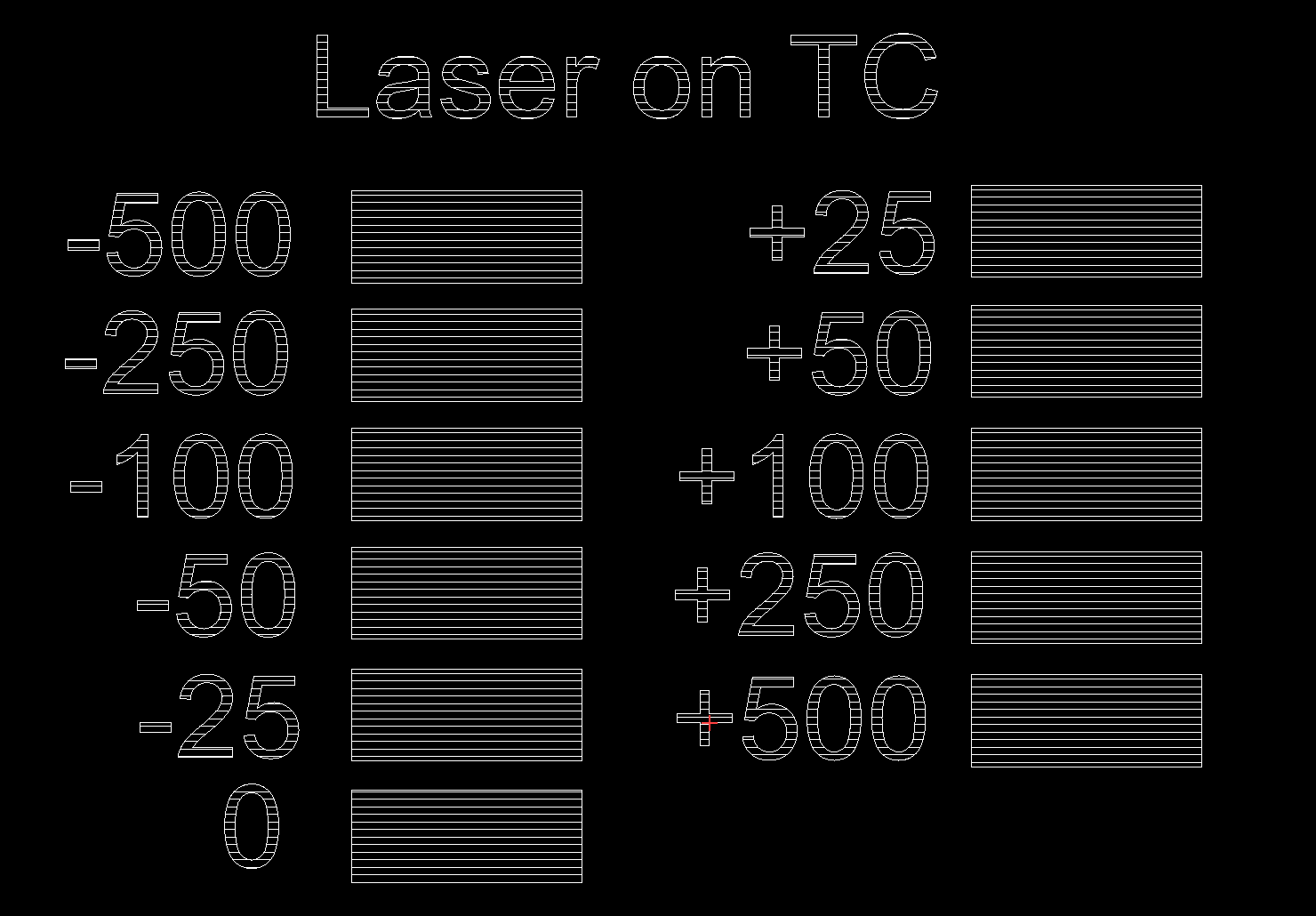
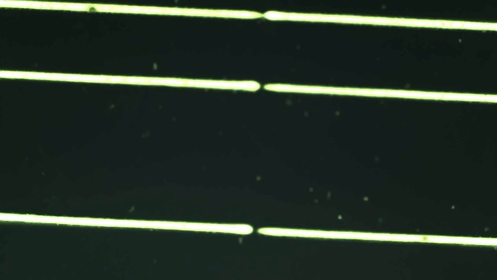
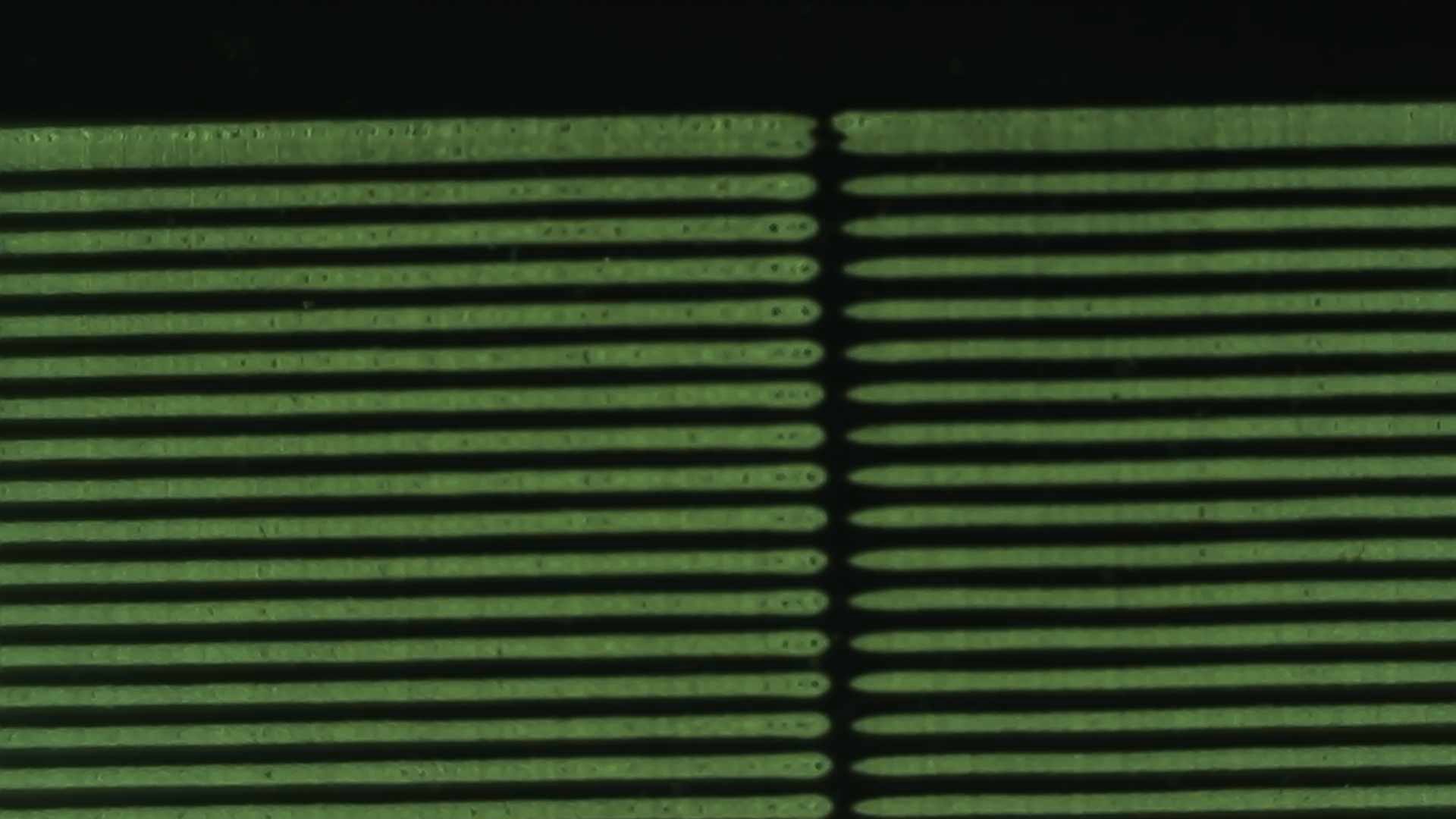
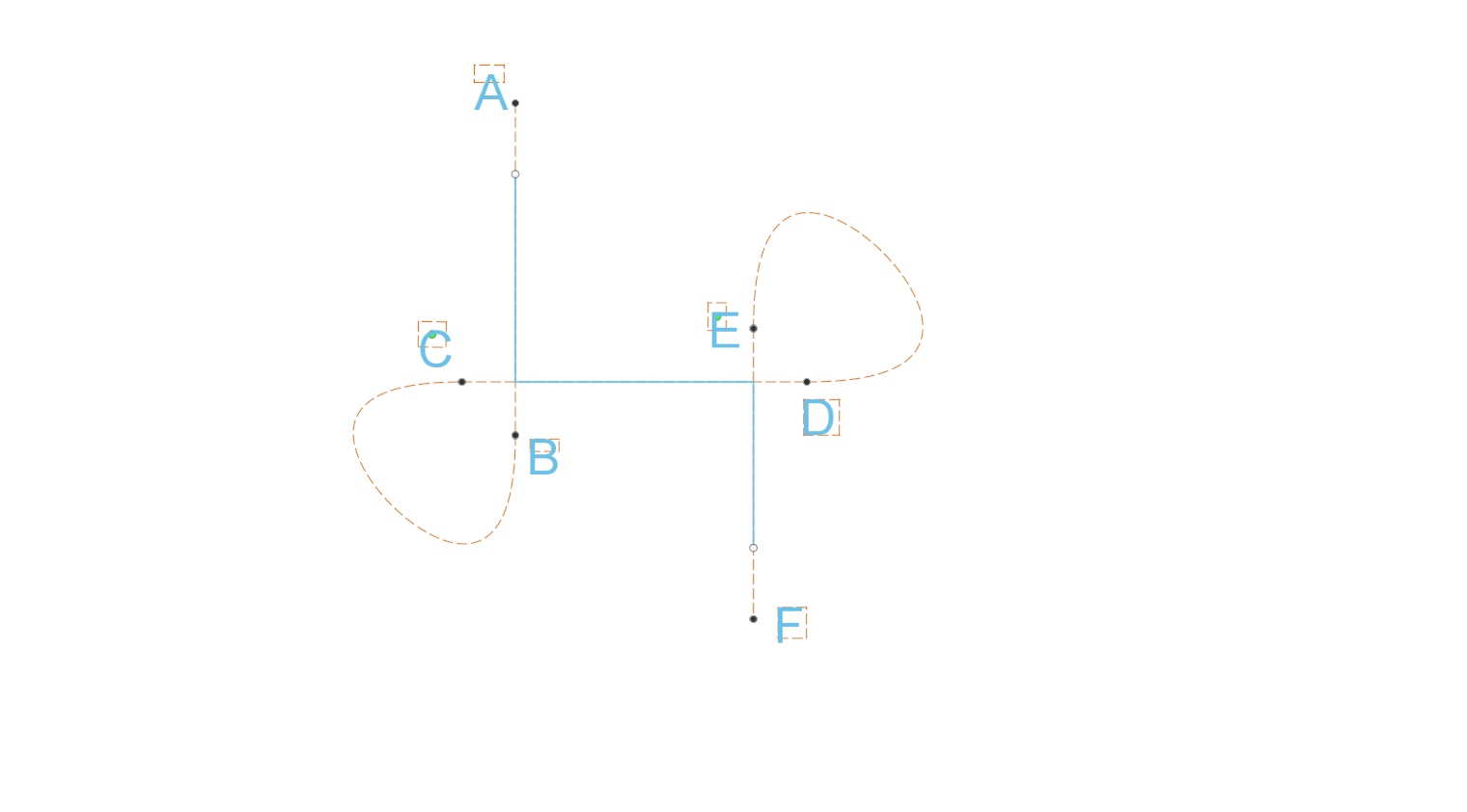
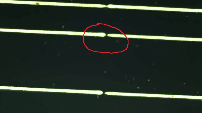
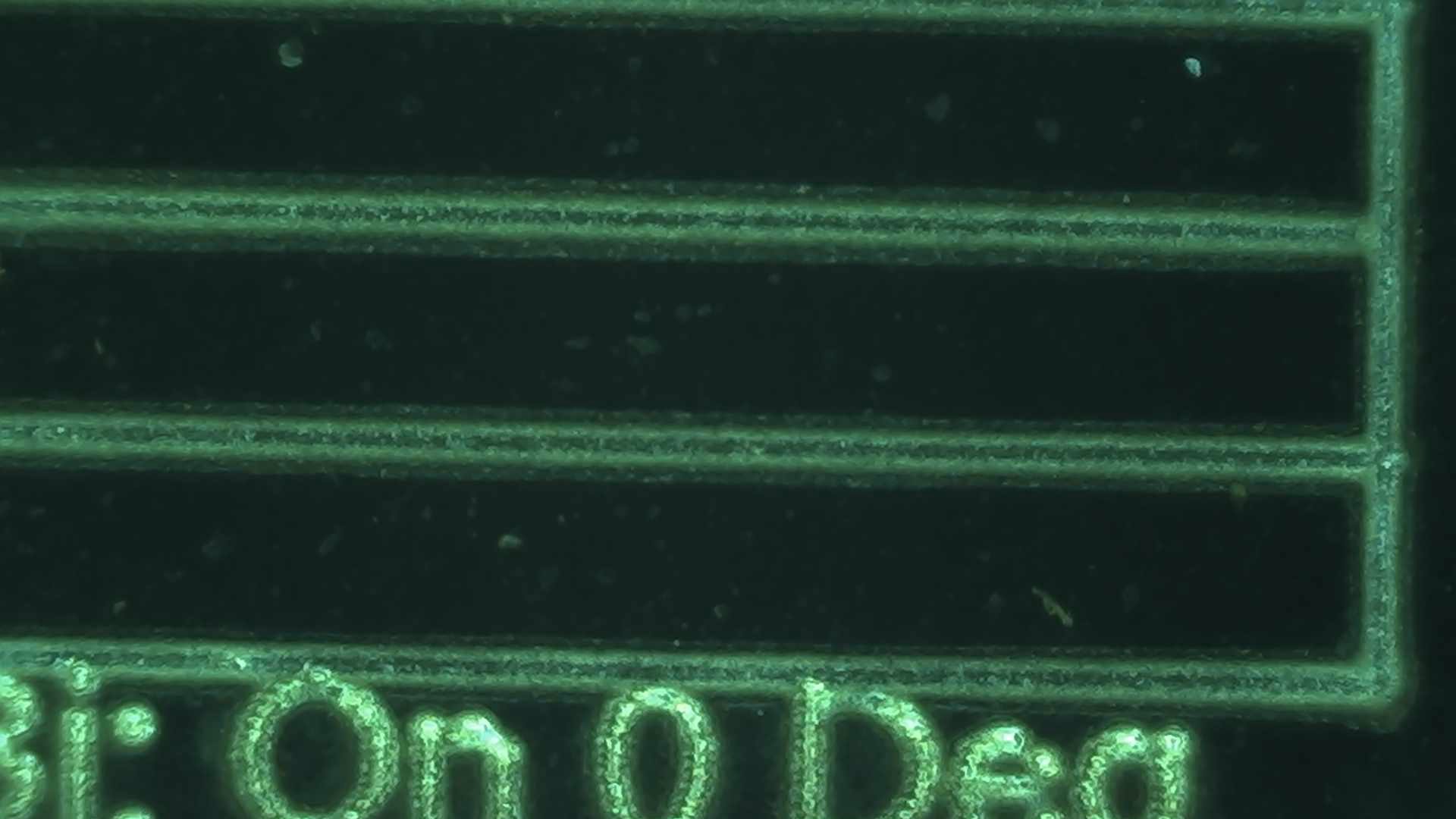
I noticed that the cut is basically flat bottom, except if I look close the edge is notably deeper. I’m running at 5000mm/s with 45 deg rotations and the timing is set very accurately. BJJCZ

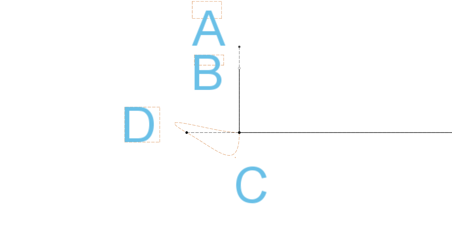
This is making me conclude that LB is commanding the galvo to the start point, and giving it the same pulse density given anywhere.

This is unlike CO2 lasers where the Ruida controller automatically calculates how far it will take to accelerate to the commanded speed, and will start the motion far enough outside the user’s cut to guarantee it is running at constant velocity at all times it is rastering. I know this is implemented in the Ruida and LB doesn’t actually control it. But BJJCZ doesn’t seem to have such a feature.

This appears to be jumping to the start point, telling it to fire at THAT point, with no “runway”, and maybe the same on the stopping edge?

Galvo are fast, but the acceleration is actually far from instantaneous.

This is pretty bad news for my attempt at precision-depth fills. Show-stopper, actually.

No, we can’t just go slower. Well, you could, but at quite a cost. I’m working on carbon steel and I can see that, on my 300W, 80ns gives a smooth bottom and will not cause bluing from excessive temps. 0.0150 LI works with the 110x110 lens’s spot size. The best result seems to consistently come from making the freq of the spots spaced the same as the LI, so freq= speed/0.015

I have been going back and forth. Longer Q-pulse keeps meaning the scan has to be slowed down more and more, and freq scaled down to maintain the sq pattern, to avoid creating a HAZ (heat affected zone). Now,100ns can also cut without creating a HAZ, but the speed and freq must be lowered together below the HAZ point and then the net removal is actually slower.

Similarly, 60ns can scale up speed and freq higher than 80ns. But of course there’s still a limit of speed and freq before 60ns creates a HAZ. Testing shows that the removal rate possible without creating a HAZ is worse than 80ns.

So, 80ns is looking great. My JPT M7 300W datasheet says the cutoff freq of 1050KHz for 80ns. That’s where I’m using all the machine’s power.

I’ve been iterating to understand this “sweet spot”. It’s quite real. I can still get a very accurate scan at 5000mm/s, the freq is still speed/LI=333KHz. Until I can upgrade my SG7110 head with the SG7210, I probably can’t go much faster.

But, the faster I go, the deeper the cut is along the edges. If I slow down, the edge effect is ultimately less dramatic. That tracks, the distance needed to reach 300mm/s as opposed to 3000ms is much shorter and shallower- but it’s still there. But then we’re crippling the machine by limiting the freq output due to this prob. The machine needs to be able to use this speed.

The answer seems obvious: the BJJCZ isn’t inserting raster “extend space” like a Ruida. Can LB add some padding length at the start and stop of each raster line?

If not, galvos are going to be flawed at a pretty fundamental level.

Or am I missing something fundamental and don’t have all my timing settings right? This is the TON/TOFF that makes a horizontal raster line doing GRAPHICS mode line up its features with a prior vector cut running vertically. So I think that’s correct

Try adjusting jump speed and your TC delay settings (especially for the corners) and the result should be better. I assume you have a low jump speed.

There is no overscan for galvo systems (not that i know of).

cheers

You may need to increase your “Laser On TC”.

That’s the “microseconds the laser will wait to fire after the mirrors begin to move. Too high a value will leave gaps, while too low a value may cause excessive burning at the start of a cut.”

Can you run the attached file and send us pictures of the result? You are looking for a range where the starting lines are just touching, without any gaps or burn-in at the beginning.

Laser-ON-TC-Calibration-negative.lbrn2 (96.2 KB)

I did extensive tuning with TCON.

That is NOT what I saw it do- at least not in graphics mode.

Say you do an 8mm raster line that is blank except for a 1mm part at 4mm to 5mm.

If you increase TON, it will shift the start point to the right. If you increase TOFF, it will shift the stop point to the right.

You need to make a horizontal raster bar with this feature and two vertical reference lines vectored above it at the 4mm and 5mm point.

If it does something different in Fill mode, that sure would be weird.

That’s the “microseconds the laser will wait to fire after the mirrors begin to move. Too high a value will leave gaps, while too low a value may cause excessive burning at the start of a cut.”

Well, that seems to be saying right there it’s not going to help. If we want to Fill from X=4 to X=8 at 1000mm/s, it jumps to X=4, starts firing at the specified freq even though it’s at zero speed as it leaves x=4. It won’t be at 1000mm/s until say X=4.2. So X=4 to X=4.2 is severely to lightly overburned per mm.

A delay won’t help here. We WANT it to start the burn at X=4. But it either needs to scale back freq depending on current velocity vs commanded velocity, or better yet start by jumping to X=3.5, accelerate with the laser off, reach constant velocity as it passes x=4 and start to fire at the commanded power at that point.

That’s true, but only until the end of the mark. If you increase the Laser Off TC (TOFF) further, there might be some ringing over the end of the line, but mainly, you see a burn-in at the end.

Could you post a picture of what you mean here? Preferably with an engraving that explains your point better.

Following along, maybe not exactly on point but another vote for galvo overscanning.
What I have found with some experimenting is the start and stop TC move the ends of the line but do not seem to change the ramp up. My lines are always thin where they start, and matchstick where they stop. I can move that thin start and matchstick stop in relation to where they are suppose to be like a fixed border, but can’t fix the shape. There is always a matchstick at the end, regardless of Stop TC or direction. Same with Start, always a thin ramp up. Possibly galvo overscan would fix this.

I am not versed in the depths of how we send commands to EZCAD2 devices - but in theory, with tuning your timings, you can avoid needing overscan and end up with the same result. I have no doubt it’s something we could implement, but I do not know how hard or time consuming that would be.

I’d recommend submitting this to Fider so we can track the feature request: https://lightburn.fider.io/

Hello Colin,

I don’t think you quite understand the problem yet. This creates a bad limitation where ALL galvos are either going to be very inaccurate on the bottom surface OR these nice high-performance machines would have to be unnecessarily slow- even then, it only only reduce the problem, not make it go away/

The galvo does need time to accelerate. It’s not much, but it will always overburn otherwise. It is fairly small at low mm/s but when you scale up to do say twice the speed at twice the freq (same depth), that lengthens the acceleration zone AND fires twice as much.

This is not a timing problem and CANNOT be improved with tuning. Say you have a horizontal line that has 1mm on, then 1mm off, then on, off, and ends with on. Three 1mm dashes with two 1mm gaps of white space in between.

The middle “on” will be correct, as it is at CV.

The start and ends will have an overburn. The cut is in the correct place. The overburn is just inside the start/stop lines.

Increasing TON delay would shift the margins of the second (middle) and third “on” start point as well, which would be incorrect. This would detune the galvo and would have sweeping negative consequences. Once you go bidir or rotation, the start points won’t line up due to direction changes and it basically doesn’t work.

This could be “fixed” when anything moves the margin of the design further out, so all 3 dashes are treated like the middle dash. For example, I add a very thin black line to the Fill operation 0.5mm to the left and right of the outer dashes. Assuming LB is configured to scan all at once, not individual features, and we’re scanning horizontally, then LB will see that line as content and have to start and stop the line scan 0.5mm further out. That’s all that we need to do so the left and right 1mm features are already at CV and have no overburn.

Unfortunately, I can’t just add an extra line that actually gets burned, as it would come out in the final design. I did wonder if we could “trick” LB by making a thin offset line that LB would recognize it as a new boundary outside the object needing to be filled, but so narrow that LB’s code might decide it should not actually fire there.

Basically if the code just took the content and did say a 0.5mm Offset around it to determine a raster line’s start and stop points, even though there’s no content to fire on there, that mostly does it. It’s not actually right because if you were burning a single horizontally aligned square with the raster lines going horizontal, it would think it needs to scan a 0.5 mm line of white space above and below the actual rectangle (if we’re literally just doing a “dumb” Offset to create the boundary).

The correct answer is pretty simple- LB’s code does what it does now to create a raster line at whatever angle it is going to do. It has a start point “A” and an end point “B”. It will always be a straight line. The design may be such that it will fire the whole time between “A” and “B”, or, as in the example above, it may have to start and stop the firing within some raster lines. This does not make the galvo mirrors start and stop within the line, only the fire command.

All we need is a few lines of code to extend “A” and “B” by “n” mm further out, for each line. The fire command will be off at A and B. As shown, LB already knows how to turn on and off the fire command correctly within a raster line, as needed. That would automatically work for the left and right dashes. So nothing particularly new needs to be developed.

You could try to go into machine accelerations that the controller reads back, which is not necessarily accurate.

Rather, the Layer settings can just have an simple overscan distance. I’m ok with that.

Actually it might be nice if that number was not a distance but an acceleration, and LB automatically scaled the overscan margin to be a longer distance when you ask for higher speeds. In that case, the parameter should be a global setting and it would just do it for all rasters.

We don’t have to take this one on right now, but the same problem does exist with vector lines. We do see the vector lines are overburned at start/stop/corners/tight curves at higher speeds due to this. That’s got some ways to correct it,.but they’re somewhat situation-dependent. The Ruida on a CO2 laser automatically calcs the ratio of its current speed to the commanded speed and uses that ratio to scale back the laser power. I do see that this sort of power scaling problematic because the BJJCZ apparently does not implement this, but it’s a deeper problem in that at least the JPT M7’s control interface uses a long, slow packet to perform a power level change so that’s probably not an option because it can’t be done at high speed. Also, I’m not sure if changing the power level when moving slower than the commanded speed would be the ideal response or not. And it’s assuming the mirrors move with constant acceleration, which isn’t actually the case. The Ruida was the one creating the steps and doing the accel calcs (which are not as simple as a fixed accel, it does slightly different things for curves vs corners etc), so it always knows its instantaneous velocity exactly. LB would only be guessing.

What LB could do is apply an overscan margin to the start/stop of every vector- that would have to be an option the user could turn on or off for each layer. In that case, it would not actually corner, but this. The dotted line is the mirror path, but it only fires on the solid lines.


LB would command a vector move from A to B, the C to D, and E to F. This not only corrects power inconsistency but rounding and any residual mirror wobble. It’s a bit slower, but much more accurate. But, in practice, it’s likely FASTER- you are free to speed up the mm/s as fast as it can go because there won’t be any rounding of corners, wobble, and power inconsistency.

Of course that’s obvious for straight vectors at right angles. But if the design’s vectors covered by vector A-B and C-D were at 170 deg from each other, this probably wouldn’t make sense to stay at CV as it passes the first corner, cut off the beam, overshoot with beam off, then swing around to point C. There are different options there, usually just a max cut-off angle of how sharp a corner has to be to do an overscan.

Tight curves are even tougher questions. My question here- I’ve already seen and understood that the JPT M7’s data interface just can’t accept power change commands at high speed. But we don’t even want that. We want the pulses to be equally spaced. Does the data interface allow the pulse freq to be changes at high speed, or is that the same data interface speed limitation? Basically, when the user asks for a line 1000mm/s 100KHz 60ns, and it’s in a tight curve where it’s doing 700mm/s instantaneous speed, the freq needs to reduce to 70KHz. Again, at that, LB could only, at best, guess what speed the mirrors are actually going. Is it even possible to write the change to freq at high speed, or does the laser source have a slow data packet interface for setting power, q-pulse, and freq and can only respond at high speed to a simple on’/off signal? I guess I need to crack open the manual again and answer that myself first.

See, yeah, this is what I’m saying. The raster needs to overscan, but so does vector. The line is matchsticked because it’s not CV yet. It’s running slow but still running at the commanded power without scaling back, and it’s getting too much energy per mm. It needs to overscan.

This problem scales up at high speeds, and really limits galvo quality at high speeds. Matchstick heads, rounded corner, mirror wobble. I think most have reacted by bringing the galvo speed back down, but that’s limiting the performance far below what it could actually do.

Basically people haven’t been complaining about it and requestion a fix because they assume it’s just a limitation of how fast the galvo mirrors can actually go in practice and still remain accurate. But that’s not actually true.

I don’t have a Galvo yet, so I cannot test any of your hypotheses. Is there a Galvo control software that works the way you’re wanting Lightburn to work?

EZCAD is the only other software out there for galvos.

I skimmed the manual for EZCAD3, it doesn’t mention overscan by name, and I don’t see anything similar documented.

The fact that “PolygonTC” exists is sort of contrary to overscan. If the mirrors took a 90 deg corner at speed, you would see overshoot. To counter that, it slows to a stop before the corner, then waits PolygonTC before accelerating in the other direction. Just slowing to a stop and accelerating alone creates overburn, the PolygonTC is needed for the mirror wobble to damped out but makes overburn even worse. If you’re doing overscan, PolygonTC wouldn’t be used because the motion vectors don’t join at corners, even though the period where the beam fires does.

And, I’m thinking this through- really I suspect the curly-q overscan I showed above probably won’t take that much longer. It won’t need to do a PolygonTC wait in a corner, just cut off the beam fire command at the right point as it shoots past, does its decel (which it does anyways to come to a stop in a corner), then it does add some extra time for the jump from B to C, but it doesn’t need extra time to let the wobble dampen out because that will likely happen in the overscan margin before the fire command starts when going from B to C.

Oh, man… OK. I’m going to make a bold, direct statement. And I’m going to back it up. Both EZCAD and Lightburn do NOT understand TCON and TCOFF and the instructions are going to lead to you miscalibrating your machine. I’ve watched several Youtube videos, usually by galvo laser vendors, on calibration and they’re also doing it wrong.

EZCAD:
“Start TC: When the scan head has to execute a mark command, the scanner mirrors first have to be accelerated up to the defined marking speed. At the beginning of the movement, the laser focus moves very slowly, which may result in burn-in effect at the start point. To avoid this, we insert a delay (Start TC) at the beginning of each mark command. When the laser eventually turns on, the mirrors have already reached a certain velocity. However, if this value is too large, the first part of the vector will be cut off. And negative value is supported.”

Lightburn:
“When attempting to mark, the physical mirrors of the galvo head must reach the desired speed before they begin marking. This fine-tuning allows the user to reduce the burn-in potential during that initial acceleration by adjusting the source timing.”

Neither of these is really correct, and if you do this, you’ll break the raster timing. And it’s confusing to set exactly- at the time, I couldn’t figure out why it wasn’t constant, and why rasters were getting offset at high speed. Now I see why. This is not what TCON/OFF is and not the correct way to set it. It would “kind of” fix the problem that lack of overscan creates, but doing so will leave the timing at an incorrect value and kind of break things overall.

I’ll do a write-up and upload an accurate test procedure with files tonight.

Looking forward to it.
I have been doing a lot of TC testing and got a 2000X usb microscope to really have a look. Even at my steel engraving at 1900mm/s issues can be seen.
And setting your TCs on the aluminum cards at slow speeds does no good, need to set them for the speed and materials you are using. I like the option to override the settings on a per sub layer basis LB offers. Make a lot of use of that.

OK, I see that my diagram of vector overscan actually wouldn’t travel along the dotted line. It commanded to these points, it would physically do something like this:

The travel from (renamed) point C does not need to run out in a straight line. Once it passes C and turns the beam off, it should immediately move to the set-up point D to pass through C again. But, as shown for this 90 deg angle, that would make the continuous spline path have to reverse upon itself.

The fast, accurate way to do this:

We designate a virtual turn-around point D and move it so that the Y acceleration/jerk is reduced enough by the time it does the X+ pass through C (now called “point E”, it’s coincident with C but occurs at a different time and direction) that there’s no ringing.

I suspect the BJJCZ controller may already be doing some of these calcs. Really, they should be done in the controller. But, I can’t think of seeing any evidence of it being done there. It’s a pretty simple calc to find a good turnaround point D in LB. This would be something that does physically get communicated to the BJJCZ to pass through these points.

A further thought- actually, this is quite definitely NOT slower. It’s going to be able to vector much faster- as long as your freq can stay below the cut-off for the q-pulse you want, you should be able to vector at a much higher speed and retail the quality, at least with straight vectors.

Galvos come with a max transit speed, and a max recommended marking speed. AFAIK that’s because the ringing will be significant above that max speed. But if you were doing the spline overscan, that doesn’t need to happen. Just have to shape the location of point D so its Y acceleration to meet up with point E is too low for ringing to show up.

Well, ok, it’s not that simple. One thing I noticed on CO2 lasers- since we have a high-wattage RF-CO2 that can give very fast response, it rasters at high quality at 1000mm/s. But, for a raster with a narrow width, 1000mm/s was actually taking significantly more clock time than 250mm/s. Reason being, imagine a raster only 3 mm wide, like you’d have with a vertical line of text. At 250mm/s, the Ruida doesn’t have to add much extend space to overscan. At 1000mm/s, it has to create a very large extend space, and it’s a fixed width, and a fixed amount of time that gets wasted braking and turning back around for each line. With, say, a 500 mm wide raster, the time savings of going 4x faster across the user’s content dwarfs the time wasted in these wide overscan “extend space” margins. For narrow rasters, the time spent on the raster itself becomes the insignificant part and the time wasted on wide overscan margins

Here’s my separate thread on how to set TCON/TCOFF correctly.

Actually, what I see is that you don’t set TCON/TCOFF based on speed or material. The machine’s timing is what it is and that is the only thing TCON/TCOFF should be set for. Recalibrating for other factors like increasing TCON to reduce starting overburn might effectively reduce the overburn and improve that one feature, but then the machine’s timing is wrong overall and you could spend forever tinkering by tweaking the timing for each material, speed, power, etc.

I do see I was wrong in assuming we’re taking lone vectors with a stop at the start and end points. Clearly that’s not the case- the start point is wide or even a pit drilled in the material, the fat “matchhead” end. But the other is a tail that narrows out. So we’re not “overscanning” by using a runway to reach the commanded speed before turning on the laser as it crosses the specified start point, but we do seem to coast past the stop point and just turn off the fire command as it passes the stop point, there’s no braking there. That more or less meets my definition of overscanning for the stop point (on unchained vectors only)

That’s specifically in the case of a lone, unchained vector. If it’s chained, like a 90 deg corner with the next vector from the same point, the BJJCZ brakes to a stop at the corner, waits PolygonTC for the mirror to settle, then starts accelerating in the other direction. It does prevent the mirror from visibly wobbling, but adds all this overburn.

This does seem to be all on the BJJCZ’s side, but it would have made more sense have separate timing params for PolygonTC for the galvo position and laser fire command. It should wait for the mirror to settle down before taking off in a new direction, but it doesn’t need to keep the beam on while doing that.

In my examples exactly the opposite, fat matchheads at the ends and narrow tails at the starts.

Here is a bidirectional test, starts bottom left, draws a polygon, then first line up from the bottom Starts left runs to right, second line up right to left, etc. I’m pretty dialed in but still can see matchstick at the ends and thin at the start.


Here are some left to right no bidirectional. Poly CCW


None of this is really that noticeable without the zoom, but when matching splits on my X table it makes a noticeable effect.


I’m going to play around with your tccal.lbrn2 file, try to get a handle on your testing/ calibration methodology. Good stuff.
Thanks–
Al :smiling_face_with_sunglasses:

Have you tried increasing the MO delay? The documentation is thin at best; I saw your other thread on this subject. I’m wondering if, when seeking peak performance out of the MOPA laser, there may be a longer time to get a steady state of of the whole system. A good definition I found in a patent is that differential firing time or dtMOPA or ΔtMOPA corresponds to the difference in the timing of the electric discharge between the pair of electrodes in the seed laser and the pair of electrodes in the amplifier laser

I may be barking up the wrong tree here though. My USB microscope released the magic blue smoke the other day, so no means to test myself.

Thank you for joining the discussion.
I’ve been following along, but to be honest, some of it is a bit over my head - especially since I don’t have a MOPA to fully replicate or grasp the nuances of the issue.

We’d love to see your results! I’ve found that using a document scanner at 1200 DPI captures fine detail much better than any microscope I have:

I ran Danny’s test at three different speeds on a Gweike G2 Pro. My main takeaway was that the ideal delay and jump settings are depending on the marking speed - not a huge surprise.

I’d be interested if you could gather more evidence showing that Galvo overscan would offer advantages, that timing adjustments alone can’t replicate.

Wow, 15000mm/s? That’s crazy!

The most common galvo used on fiber/MOPA is the SG7110. Spec is supposed to be 8000mm/s travel and 5000mm/s for marking. Actually, it looks like you can still ask for speeds up to 8000mm/s while marking, it sounds like they just don’t recommend it because of reduced quality.

Aaron, your capture seems a bit confusing to me.

I did say that on my MOPA, speed didn’t seem to make a difference as far as the best TCON/TCOFF value. It seemed basically insignificant. I wouldn’t be surprised though if another machine had a different TCON/OFF shift with higher speeds.

The thing is, I’d expect to see a SHIFT. Specifically, to the right, if the unidirectional raster takes it left-to-right.

What you’re showing, though, is that total on-time is contracting. the left starting edge is lagging. But the right edge ends too early. I am indeed surprised if this is accurate.

I would have expected that if there was a change in timing, it would shift both edges equally. Why would it be ending the beam prematurely?

I even see this at 5000mm/s. Start is a little late, end is a little early.

Are you sure it’s filling all the rectangles at once? Each horizontal raster scan covering all of them, as opposed to one rectangle filling bottom-to-top, then stepping over to the next one?

Or, well, is it strange? Or does this make perfect sense? TCON/TCOFF are fixed times. It looks like it’s just that TCON is 0.83ns too high and TCOFF is also too high but by 4.17. At 5000mm/s, the distance of the fixed timing error would be 1/3rd the distance. The 5000mm/sec chart looks like it’s off by that much. And 100mm/s the distance is 1/15th that of 15000, which would make it smaller than the spot size which makes it really hard to see.

The vertical tick lines we can still look for their center if the power was higher and burned them wider. But the rectangle fill, if we give it more power, the diameter the beam cuts gets a little wider, so it widens the raster a small amount. I would say the TON and TOFF errors are the same on the 100mm/s burn, but they’re very small, and the Fill power level/pulse freq may not have been scaled down as much and burns slightly wider, washing out over that tiny amount of distance error.

This does show the importance of the timing test for sure! You see what this means? If you were to do a crosshatch raster at 15000mm/s, the first pass burns the left side 0.03mm too short and the right side is 0.09mm too short. But the top and bottom of the rectangle of course just line up.

The crosshatch 90 deg pass, however, will miss the top 0.03mm and bottom 0.09mm of the rectangle. It will burn over the portion missed by the first pass, so there’s a smaller rectangular region which sees two burns but all 4 sides have an inside margin that was only burned once. If a feature in the artwork is smaller than the margin size to begin with, it will see only one pass out of two. Doesn’t matter which pass hits and which skips it, it’s only hit by one pass.

If you want to show off your scanner one more time, do 15000mm/s raster on a high resolution image in single dir, bidir, and 45 deg rotation bidir.

Then correct the timing, check it with the test to see if it’s exact at 15000mm/s, and redo the same rasters.

WHAT THE F*CK??

I went refining a more precise test- now you just do at most 8 decimation steps and it will always get you an exact number- to the microsecond- with no guesswork.

THIS IS AMAZING!!!

OK, at first I was really happy I got an exact number for the TCON/TCOFF. Then I went experimenting and every single new thing I thought to test just blew my mind!!!

First off, high-speed and high-res raster image quality went through the roof.

My common SG7110 scan head is rated for 7000mm/s rapids. But vendor info on Aliexpress only rates it for 5000mm/s marking.

Well, I just scanned 1.5mm tall SHX fonts at 7000 mm/s. It is flawless under high magnification, it looks nothing like I’ve ever seen at this level. Everything is straight, the corners meet up dead-on, there’s very little “overburn”, and no “matchsticking”

I dove down that rabbit hole and I see the problem. You MUST have TCON/TCOFF set precisely- to the microsecond- or all subsequent cals will be “off” and it creates a confounding problem with the other parameters.

The ramifications here are pretty profound. We haven’t been calibrating these correctly- no one, apparently. With the right test, getting precise cal is easy.

It appears that the only reason galvo heads aren’t recommended to be used at anywhere near their max speed is actually due to lack of accurate calibration routines.

The TCON/TCOFF does NOT change with speed or q-pulse. You cal once at max speed and it will be valid at lower speeds. The reason people saw the cal needed to change for higher speeds was that it was always “off” by quite a bit but the consequences just aren’t as significant at lower speeds

Now I understand more about the galvo’s motion control- Overscan now seems unnecessary, in fact I suspect LB may not even be able to tell it to do that as that level of handling comes from hardware

1 Like