K40 homing in wrong spot

Since you have eliminated all the parts, that leaves the configuration not being correct… which doesn’t make sense either… since it was mostly working.


There are plenty of people here that will buy it from you and get it running. Just takes a bit more time and patience than you are willing to expend. It’s just a machine… They do work, seems your frustration level is pretty intense, this leads to jumping to conclusions creating other problems. If you’re not too far away I’ll pay to have it shipped here… :crazy_face:

Don’t work on it if frustrated and when you do, work for shorter periods.


It also complicates the problem if you have more than one contributing issue, such as a combination of hardware and the controller configuration.


What seems to be lost here, is that it was functioning and all this stuff had to be working, at least a majority of it, such as configuration. It’s more than likely you didn’t ‘hurt’ it moving the gantry and it was just coincidental to that operation that the problem occurred. You have changed out everything that could effect, with no success.

Good luck

:smile_cat:

I have been following this for a while and at this stage my money is with Jeff. I think its a broken wire, bad connection or a short while homing.

Where else can I look?? I would like to keep the machine it’s been fantastic. It also sounds like it was a coincidence in the timing with moving the head. I’d like to try changing out the whole wire but I can’t find one to buy. Even though it checks out on the meter maybe there is a break in it I can’t see. I know the machine is “dumb” changed the board out. I don’t think it’s belts or anything it functions perfect just not homing. I mean there isn’t a whole of parts in them.

So my question is where can I find a wire harness for those limit switches?? That’s literally the only thing left Ohio to change out. If that doesn’t do it it has to be software. Everyone here has been super helpful.

Anyone know where to get the wire harness??

Instead of blindly swapping parts it would be better to isolate and diagnose the issue.

Is there a reason why you haven’t tried swapping the X and Y pins of the cable? That would tell you if the problem can be attributed to the switch/wire vs the controller.

And besides, if you can’t get the switches to trigger correctly you won’t have any chance of getting it working.

I suspect either the X or G cable is shorting… If not that, the SD card may be corrupted.

This is very easy to do, mark the wires and block positions with different colours, push in the retaining clip easily with a pin pull the wires out and swap over. It would be another step confirmed or ruled out. Then you could deal with the common ground wire if needed.

The way to fix something is to find the problem not the shotgun approach you are taking. That voltmeter does more than measure continuity You need to make effective use of it’s abilities to help you solve these types of problems.

It may be something you need to learn to use, they are not intuitive and you don’t learn how they work by osmosis…

With the KISS priciple in mind, the controller is looking at a voltage on the pin, measure the voltage to that pin. That’s what you care about, not continuity.


It’s also possible that we are not communicating. You tell us what you did and we assume certain things.


From the beginning it didn’t home, it would engrave an image and work everywhere else. That literally eliminates most of the hardware used for a homing cycle.

Homing is the issue and it needs to be addressed, not by a major swap of parts. What if the board you purchased had the same issue?


When you do a part swap, you increase the possibility of inducing other issues. I’d forget about swapping out the wiring. There is little chance there is an issue with the ‘harness’.

It’s much more likely that the issue is at the mechanical ends of the wire. Where it was crimped or put in the connector. Wire rarely breaks when it’s static or only moves a small amount.


If you wish to proceed I suggest you find out why it isn’t homing. And quit guessing. This should have been an easy fix considering the mess and frustration you’ve created in an attempt to solve it irrationally…

Hang in there :crazy_face:

Good luck

:smile_cat:

I ordered another cohesion board with a fresh SD card and installed it.

I would like to fix it. I’m learning as I go some of these things I have to figure out how to do. Maybe a litttle embarrassing I don’t know how to do some of the things your asking. I’ll try and switch the wires around today I’m working from home.

That’s all we really need to know… :smiley:

IMHO, put it back like it was when it had only the homing issue. Then use a good troubleshooting approach to find the cause and resolve the issue.

That encompasses checking voltage levels and not 'ohm’ing out stuff to see if it has continuity. Which hasn’t helped you get anywhere except buy more expensive parts you don’t need.


None of us think of who we help as a ‘dummy’ (wouldn’t be on the Lightburn forum if that were the case.lol). I’ve got almost 60 years of electronics as a profession, a hobbyist and an amateur radio operator.

I don’t know if your ‘technical’ ability is limited to weaving a bowl or designing quantum computer hardware… if you follow me …

It should not be embarrassing to admit you don’t understand or how to do something asked of you. I completely understand that feeling in any case. We’d much rather you tell us you’re clueless than to think you are doing the tasks we asked of you to help you find a solution.

All I’m advising is proper trouble shooting techniques. This would be a proper trace of a signal, forget the continuity bs…

For example. If you measure the ‘pin’ and it doesn’t go low (or high). I would not unplug the connector and check continuity. The next point is where that is coming from or back to the the switch, measure the voltage there.

This kind of process generally pinpoints the issue. If there is no signal at the pin, but there is at the switch, you know the switch is working and the failure is between the two measured points.

There is no reason you can’t check the switch first then the ‘pin’ for proper operation. In most circuits, like radio you follow the signal until you ‘lose’ it. Between where it ‘was’ and where is “isn’t” is the failed ‘part’. Use your brain instead of your sweat and wallet to fix this stuff. Substantially lower cost and much easier on the frustration.

You may end up taking a guess, but make sure it’s an educated guess. The technique I specified should eliminate most of the guesswork.

:smile_cat:

So I unplug the wire then test voltage right on the pins while hitting home?

Leave it wired like it’s supposed to be. You are going to test it as it’s supposed to work. The signal is not being seen, not making it there or some other issue causing it to fail.

This should tell us if the switch is changing the ‘state’ of that pin. That’s all. If it’s changing, there is no problem from the switch to the point of measurement.

What @berainlb was after is to simulate these inputs manually by triggering the switches while it’s attempting to home. Lets do the measurement, it will tell us what is happening. You have the tools there, use them properly.

If you can do your checks as the machine is supposed to work you ‘see’ what it’s doing.

Good luck

:smile_cat:

I was attempting to isolate the issue between switch/wiring vs controller as well. The test you’re suggesting will test for the function of the switch/wiring in isolation which is fine but it won’t tell you anything about the behavior of the controller side.

However, if you confirm the switch/wiring side in isolation then you could retest to validate the function of the controller.

I could care less about it working off the machine. The problem is it fails. I am chasing a signal that I know has to be in a certain state or changing state.

Following good troubleshooting techniques, unless it’s smoking you don’t disconnect things or swap things if you can simply measure the voltage which confirms that it’s working, I.E. getting the proper signal to the controller or not.

If it doesn’t work at the switch or doesn’t make it from the switch to the controller you have identified a problem. If the signal is at the controller, you know it’s working up to the controller. All the controllers I’ve worked with (about 1/2 dozen) have, at max an r/c network for noise, but that’s it. It goes right into the Arduino. Even with a Ruida, if the signal is at the controller the circuitry that signals it is working.

Again, I’m follow the only lead we have up to the controller. It’s in a running state, what is isolated?

If anyone is isolating it, unplugging it is taking it out of it’s normal operating circuit is, unless that’s a typo…

I do this in one step, no retest, check the voltage at the pin on the controller. Don’t care what it does in isolation, I want to know what it’s doing when it fails during operation. Might operate differently as an isolated unit… lol

All I’m trying to do is simplify the troubleshooting process.

If I’ve learned anything in the past half century fixing this junk, it’s follow the offending signal


I notice it when I tried to run a job one morning, it started, but my chiller was off… it should have given me a wp error. It tried to run the job with no coolant flow. Fortunately, I noticed the issue and stopped it before it lased.

The Ruida failed in an ‘active’ state on it’s water protect (wp) input. I can see the LED on the controller turn on when wp goes active, so I know that’s working. If I look in the ‘diagnostic’ screen of the Ruida, I can determine that the internals of the Ruida are not seeing the signal. The fault is clearly in the Ruida. So I have no wp input that is usable on this controller.

:smile_cat:

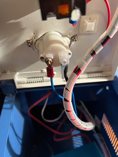
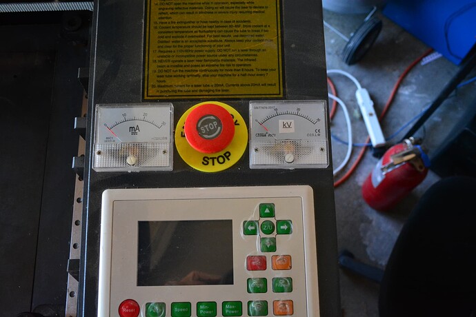
Fixed!!! On my analog meter the connection was loose tighten it up hot glue and everything works!!!

This was the culprit I guess

Great you have it fixed… don’t understand what was going on as there should not be a need for it and there is no current flow through it when homing.

Sad you decided to put hot glue on it… :frowning:

Good luck

:smile_cat:

That’s how it came when I bought it so that what I put back. What’s a better option?

Probably why it failed… hot glue on electronics like this is not really the best idea. For one you can’t tell if it’s lose, which is what bit you…

I’ve seen these meters in service for 60 years and they don’t have a problem with just a tight nut.

I have two on mine and they are just good and ‘snug’.

I sometimes run 1600mm/s plus and nothing has shaken off yet…

:smile_cat:

You’re saying the ampmeter connection was loose? I don’t understand how that would have caused your symptoms.

Out of curiosity, can you run M119 and post results? I’d like to see what it’s supposed to look like in a working setup.

Sure give me a few minutes. I know it’s weird everything I read and you all on here was leading to something between the likit switch and the board. When I was messing with the machine I caught a little arc out of the corner of my eye and there it was. Now in all fairness I replaced my limit switches with new ones so maybe it was a combination