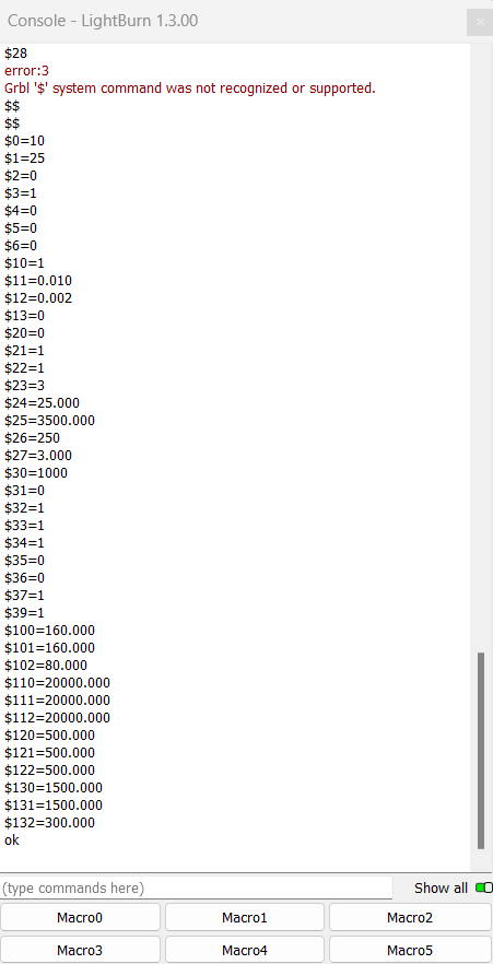
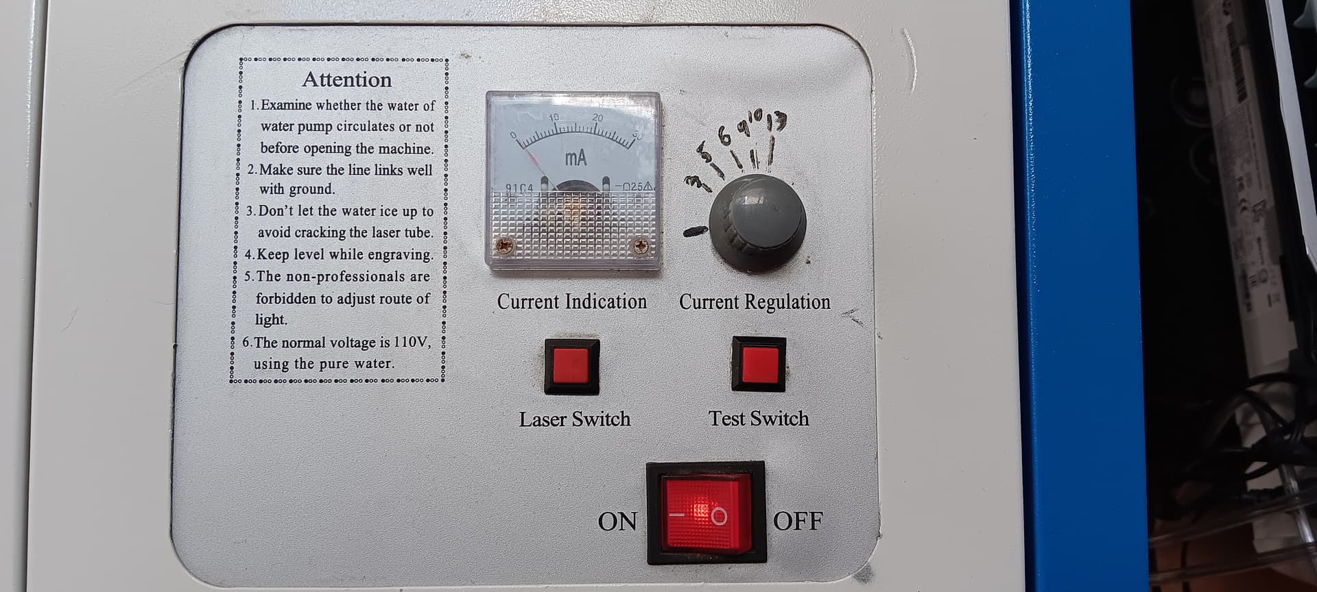
I have an older K40 with the “Green” PSU and my M2 Nano had the ribbon cable. I just upgraded to the Monport V2 board so I could use Lightburn on it, (I’ve been using LB on my Ortur LM2 for the last year). I installed the board and find my laser and pulled up a GRBL 1500x1500, I clicked on it and changed the bed size to 300x200, set my home to the rear left and clicked save. It homes fine, I can move the laser but when I try to engrave or cut something I’m not getting very much power. My ammeter might hit 4ma. Here is a list of my setting from the console.
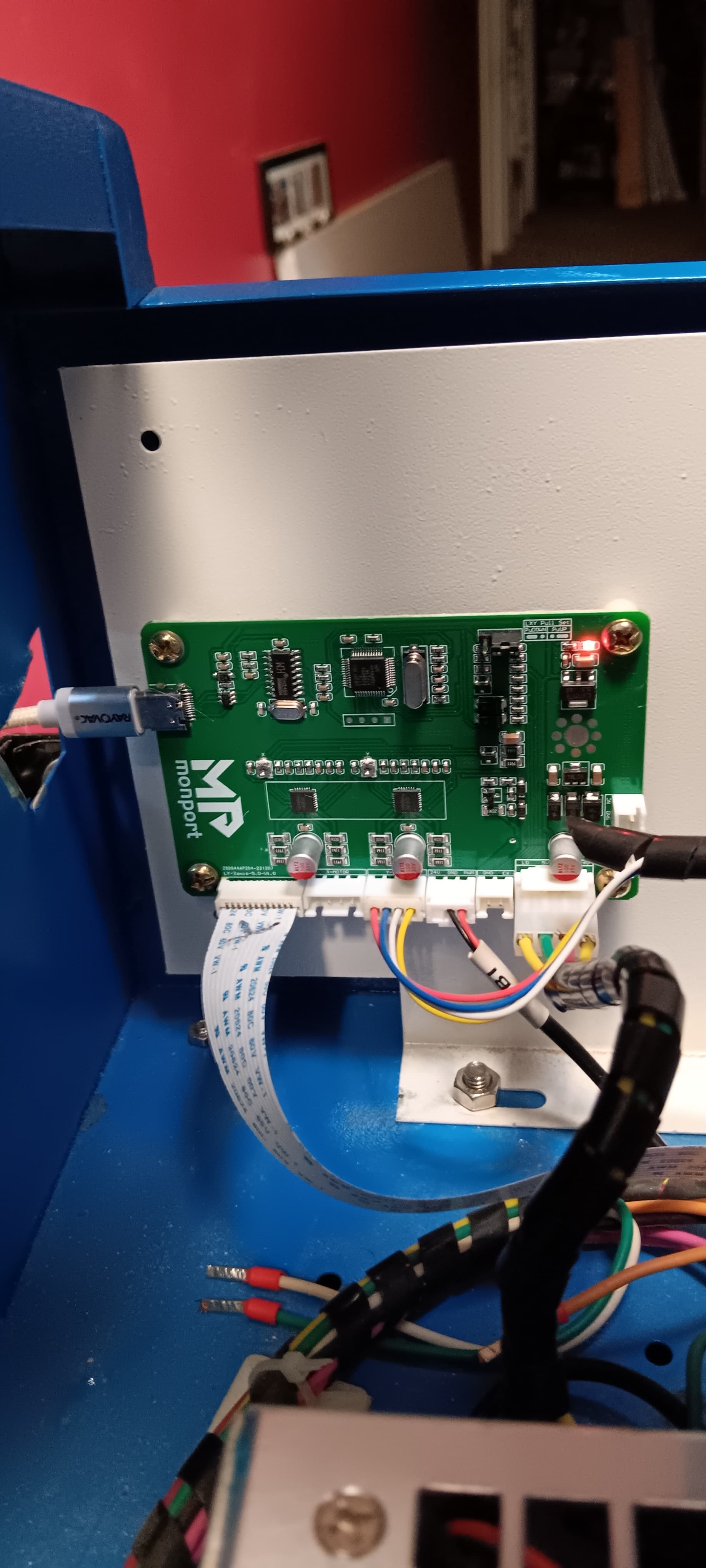
Attached is a pic of the Monport board. PSU I removed 2 or the potentiometer wires (5 & 6) on the PSU and ran a jumper between 3 & 4 (laser test button). Also when I power on the K40 the laser fires up to almost 20mA for a split second, I have a video but I can’t load it on this forum.
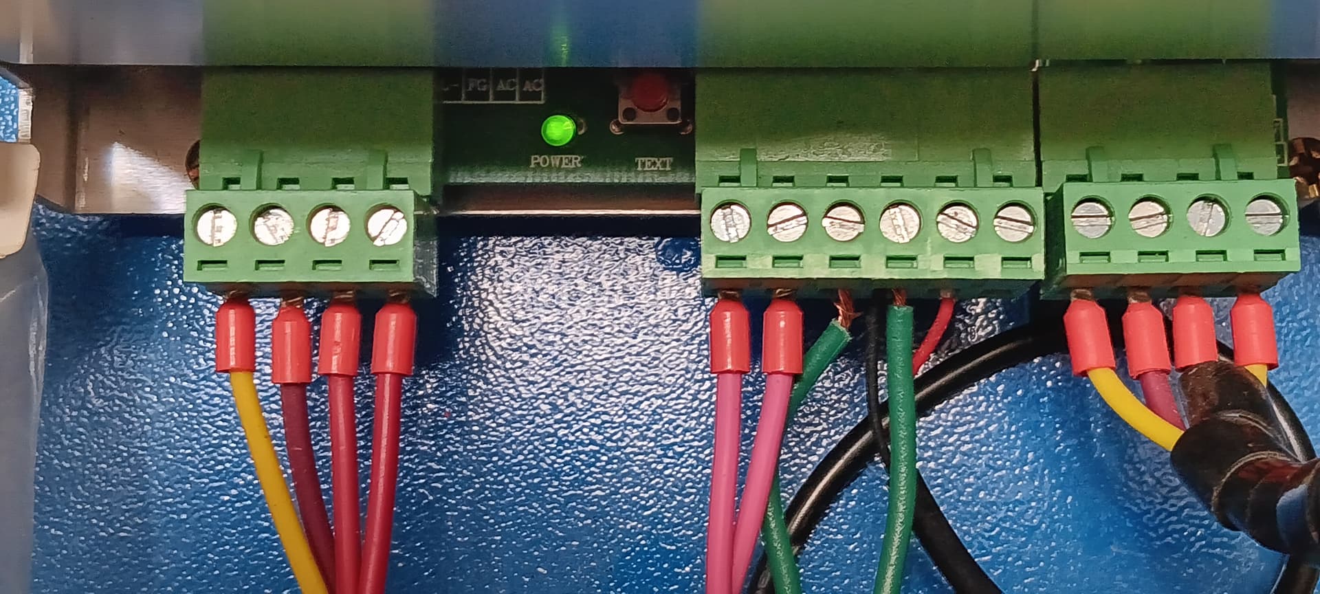
If possible use signal names or at least give us a photo that show what signal is what… usually a lower angle has the signal names labeled. Many are very similar, but not all are the same.
The pot wires you removed? These control the lps current limit. What do you have in place of the pot or what wire goes to the IN terminal of the lps?
If all else fails, provide links to the product component, such as the lps, so we can try and help. You know what it is, we don’t.
This is probably what’s causing the tube to lase when you power it up…
Why/where did you get the information do change this wiring?
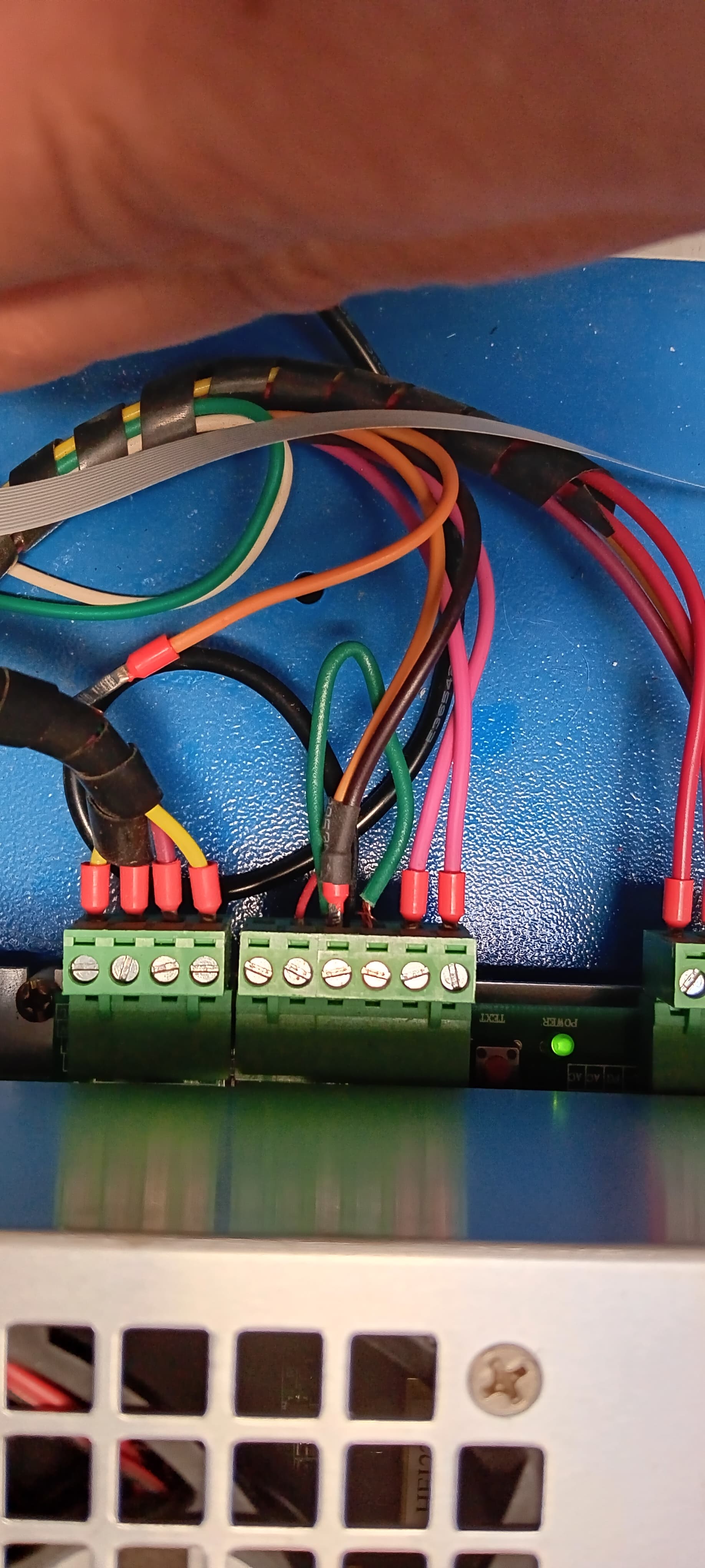
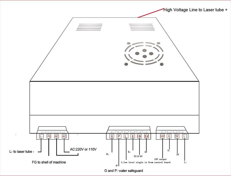
Jack, thanks for responding. I cant find any wire labels on my PSU so I’ve been searching the web. I believe its the same as this “Green PSU”. In the picture “My PSU wiring” from left to right I have (1 & 2) pink wires are from the laser on/off button, (3 & 4 used to be laser test button) green jumper wire and 4 also has the black “GND” wire from my Monport board and 5 is the PWM red wire from the Monport board. Let me know what else you might need to help my figure this out. Also I used this video to help with some of the wiring, around 13:50 is the wiring. https://www.youtube.com/watch?v=XqrFxjf6y7I&t=845s
Let me try to explain how the monport board is controlling the lps with this configuration.
Starting at the left of the center connector. The P input is a water protection input that is usually wired to a pressure switch indicating you have coolant flowing. Sounds like this was wired through your laser power switch. To enable the laser to fire this needs to be pulled low or to ground. The jumper to ground makes it active at all times.
The L input is the laser enable. When this goes active (low) it fires the laser at the IN voltage/pwm value. The jumper to ground makes it active at all times.
In essence when the pwm goes high it will lase.
The pwm actually produces a voltage within the lps that specifies the current limit.
Jack, that kind of makes sense to me. So my L and G2 have a jumper to connect them together which makes the laser active all the time? Should I try to remove the jumper and have the Monport PWM to the IN on the LSU control the laser?
I think that’s the way it is described using the video.
I’d suggest removing the jumper for the laser power switch so it can’t lase unless you enable that switch.
My lps has a switch that just controls the mains voltage to it. Most of my safety stuff has been removed, so I’m not hard core, but I think it would be wise on these to go ahead and use it… It can’t hurt anything…
Right now what is the status, does it still fire when you power it up? If you put the laser power switch back in, it shouldn’t… if you have it off… You don’t have to turn it off …
There is a main power and there is a laser power button that is connect the G&P together. I’ll remove the jumper and see if that helps. All I really need is to figure out how to control the laser power through Lightburn. I can get it to fire but I cant get it to go past 3 or 4mA’s
If you have a voltmeter you can easily measure the pwm voltage level at the lps or controller pin.
It’s a ttl signal, 0 to 5V. If the pwm is 50% you will read 2.5V, 20%, 1V…
That’s the best way to tell… it would be nice to have the laser power switch where it was originally because you can test this without the lps enabled.
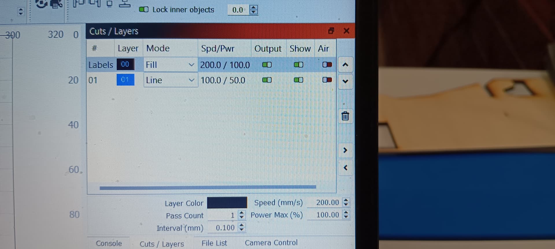
Jack, you are definitely helping! My setting are 200mm/sec at 100 power and on short passes I’m getting up to about 3mA and longer passes up to about 8 or 9mA. I have videos but I don’t know how I can post them on here.
I’ll grab my volt meter and do some tests. I can try to hook my test button back up and see if the works other wise I’ll just run some tests in LB at 20, 40, 60, 80 and 100% and see if I get 1,2,3,4,5 volts between G2 and IN.
You might need to adjust your spindle max RPM value ($30) to match the LightBurn default (1000) or vice versa. The value in LightBurn is called “S-Value Max”, in the Device Settings.
Ok, the laser switch is still connected and pressed in for ON. The s value is 1000 and the $30 is 1000. I’ll go back and re-read the GRBL setup documentation and make sure I have it set up correctly. I’m not sure if I need to have constant power on or off.
So I ran a test 100mm/sec at 20,40,60,80 and 100. I put my probes on G2 and IN and I didn’t get the volts was looking for.
20% = 1.3V on Fluke and 3 to 4mA on the Ammeter.
40% = 1.6V on Fluke and 4 to 5mA on the Ammeter. This was 100mm/sec not 10 as I changed it before the test run.
60% = 1.6V on Fluke and 10mA on the Ammeter.
80% = 1.6V on Fluke and 16mA on the Ammeter.
100% = ??V on Fluke and like 20mA on the Ammeter. I stopped this one as I was worried about the laser tube and to much power.
I specifically stated to turn off the lps… If your laser switch is wired to the lps, you can prevent it from lasing.
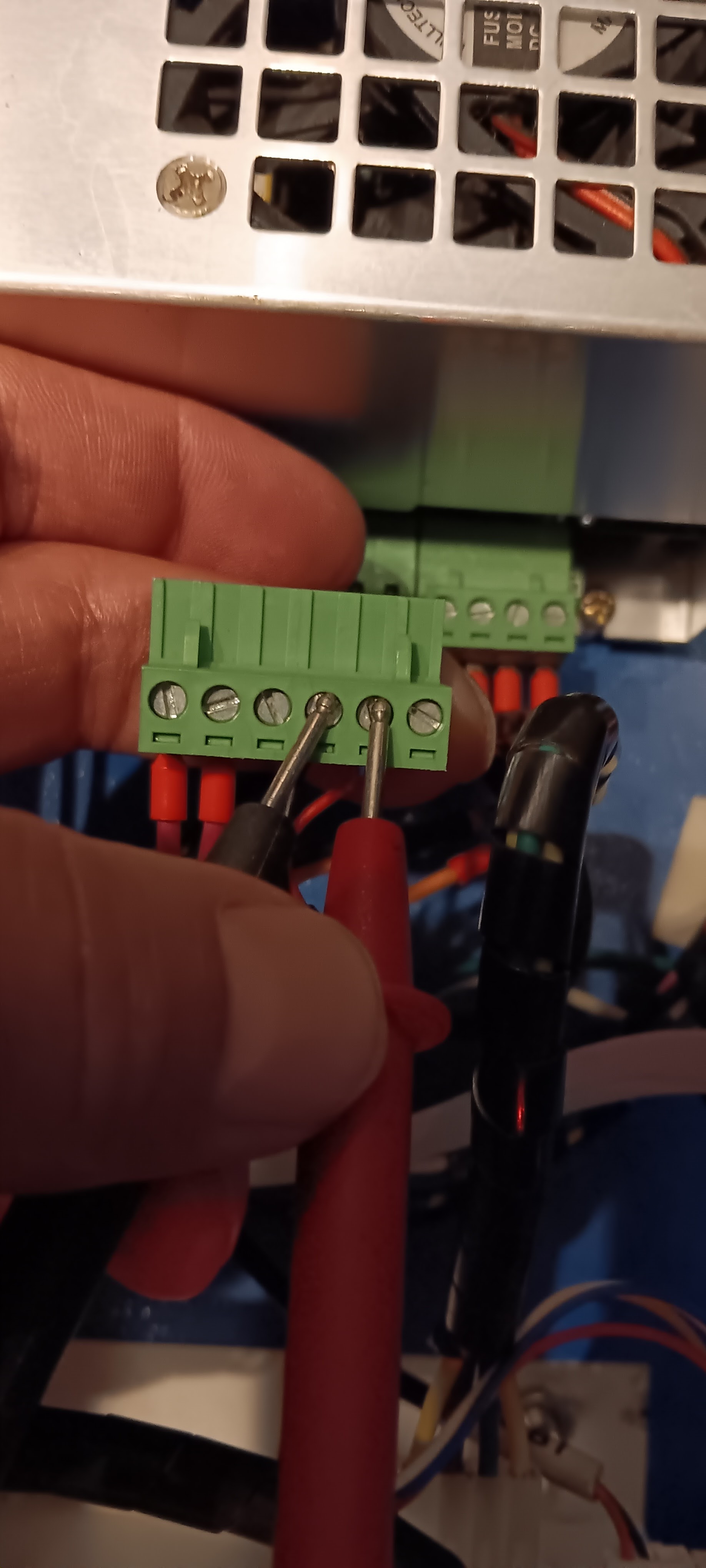
Unplug the signal connector (center, 6 pins) and measure the pwm signal at the control board side. It should not lase…
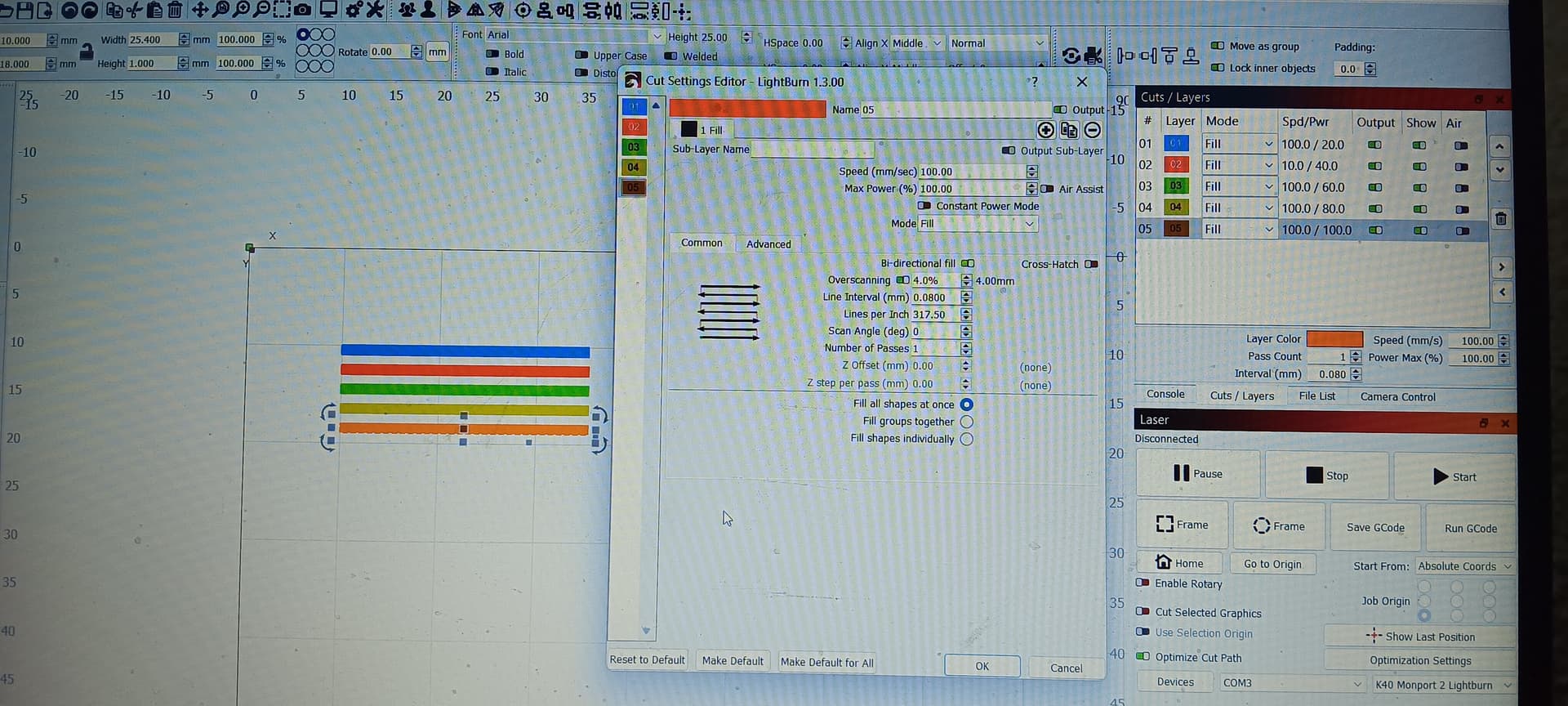
Run a layer at the % values… 30% → 1.5V, 50% → 2.5V and 70% at 3.5V along with 100% → 5V. All the control signals are missing, so the laser should not be firing.
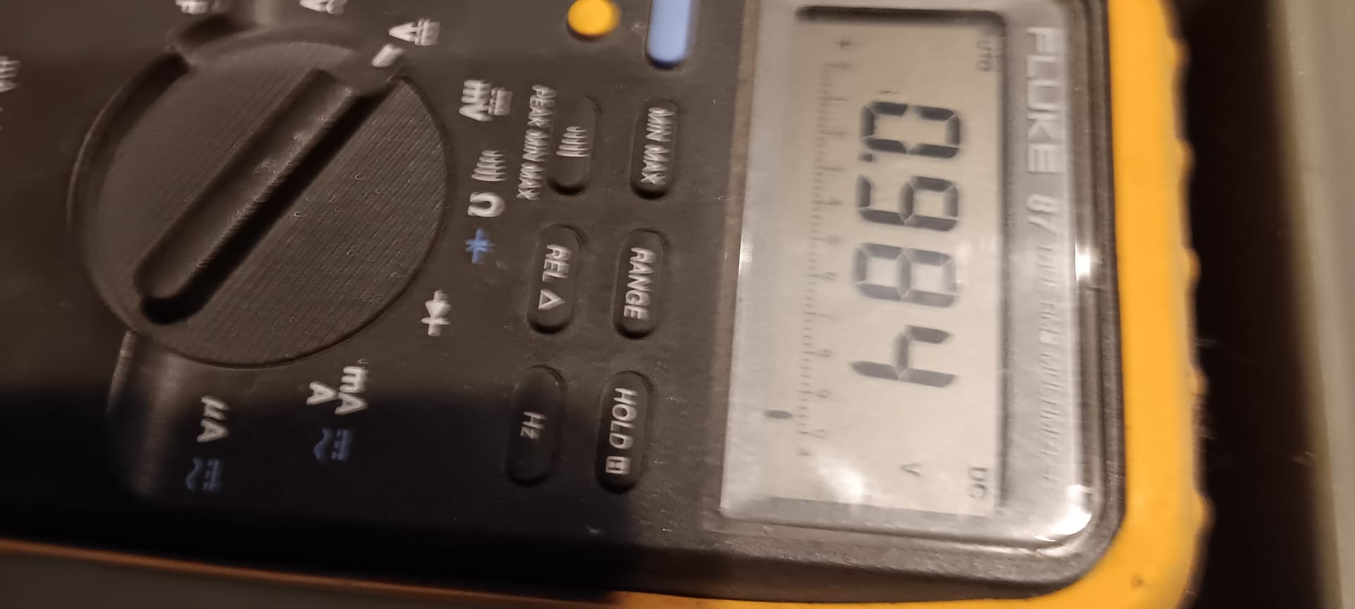
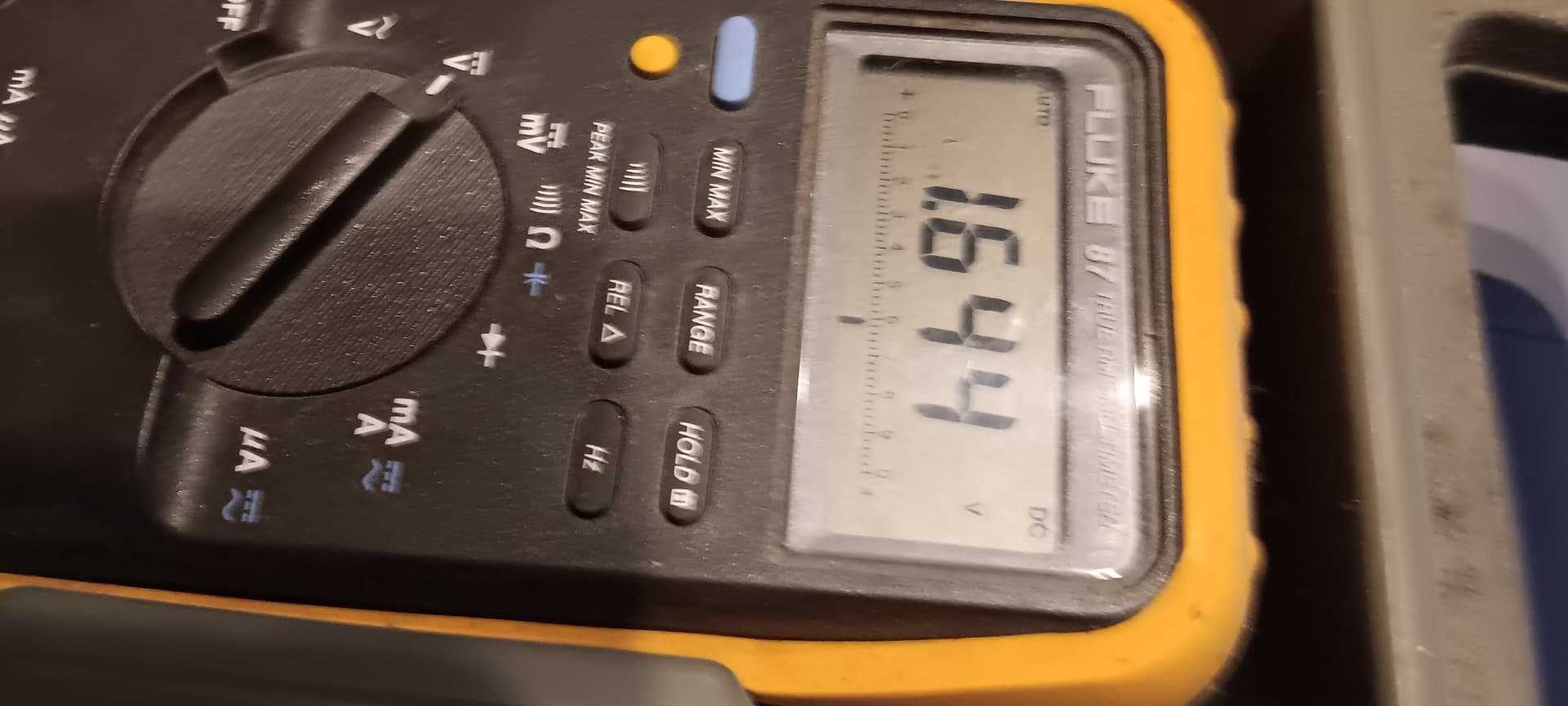
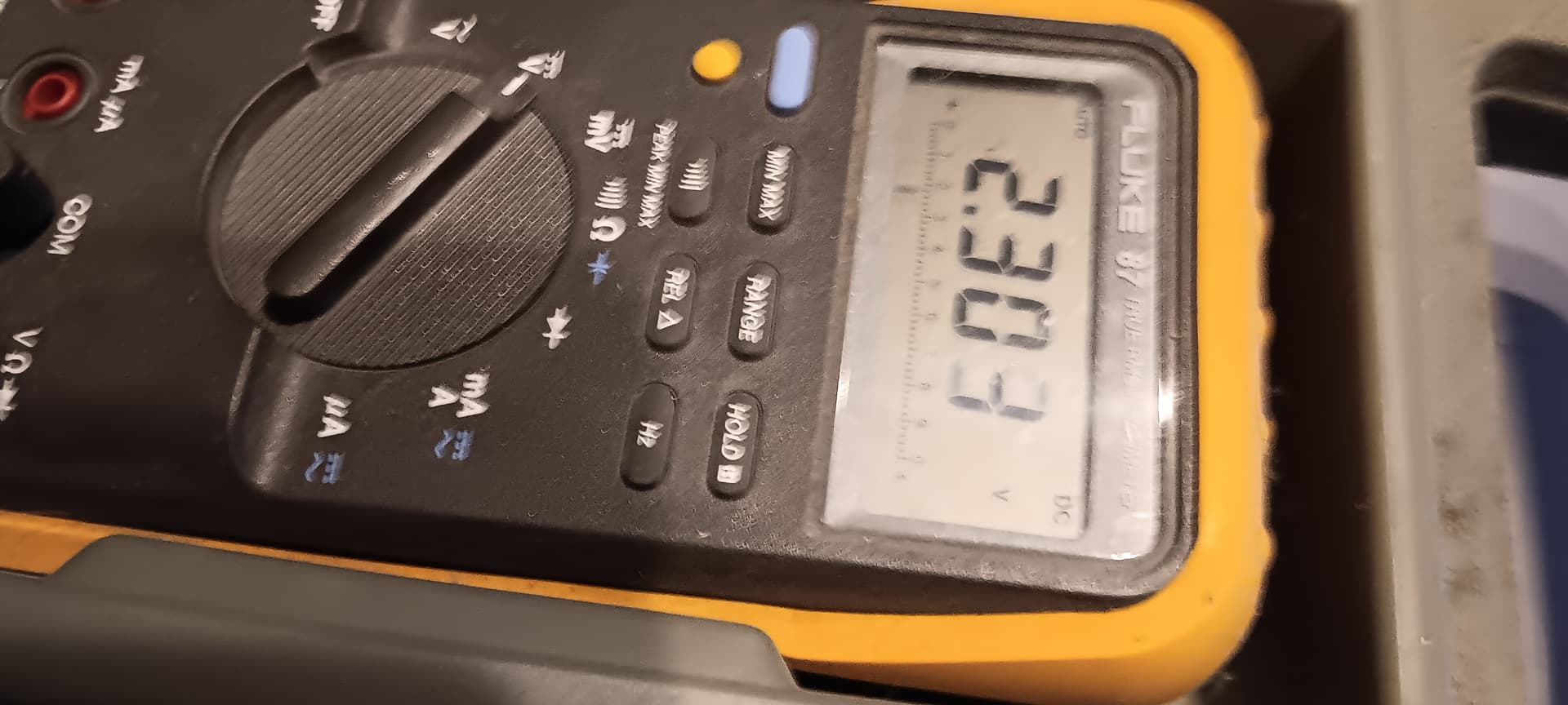
Sorry Jack, I’m still new to this. I unplugged the 6 pin connector and I tried to measure it again, I tried it on AC volt and I wasn’t getting any consistent reading so I tried DC volt and I got 30%=1.00V, 50%=1.66V, 70%=2.32V and 100%=3.14V.
Although with a 3.14V IN voltage, that relates to about 63% power, so I’d expect more current than your 4 or 5 mA value.
If the controller is not producing the required voltage, it has a problem.
Double check and make sure you’re reading the stated values while it’s control signals are disconnected from the lps. You should be in dc on your meter…
Even if the control board is faulty, you should be getting 63% power or about 25W out, with a draw about 11mA… So something isn’t right.
I don’t know which reading is for what percentage power…
However, if at 100% it doesn’t read 5V you will never be able to tell the lps to run full power…
At this point all I can advise is to double check
You might need to adjust your spindle max RPM value ($30) to match the LightBurn default (1000) or vice versa. The value in LightBurn is called “S-Value Max”, in the Device Settings.
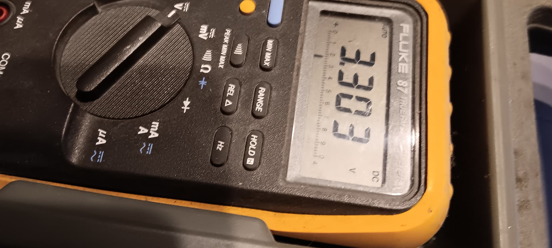
What is odd, is that 3.3V is the supply on some of these boards. What ever the board is running, the output has to be a 0 to 5V analog or digital pwm…
Other than that, I guess you’re looking at a new controller… don’t know what else to check.
Even with the 3.3V you should be drawing more than 5mA.