Laser missing details while engraving

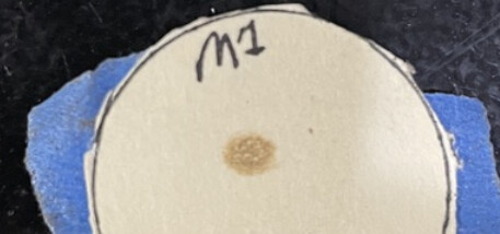
Does this look like a circle, even power, dark in the center and gradually gets lighter as it goes outward?

The center sure looks odd… Might want to pulse it twice… It’s definitely not round.

image

This is from m2, pulsed at near and far… the distant pulse is the darker of the two. Although not perfect you can see dark center and lighter going outward. Next time I check mine, I’ll have to take a photo for an example …

:smile_cat:

I’ve been assuming all along that the mirror holders have a circular entrance aperture, so that the tape / paper will be perpendicular to the beam. In that orientation, the beam should be nice and round.

If the tape / paper is on the mirror, then the beam shape will be oval due to the 45° angle, which is perfectly OK.

Good clarification. The mirrors are not perpendicular to the laser. They are angled.

What would be the next step?

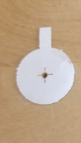
AFAICT, the beam looks Just Fine™.

If scorches at both ends of the axes overlay each other and the beam comes out of the nozzle in the center, then the alignment is also Good Enough™.

Now you should be able to run those wood coins or cardboard dummies with much better results. Do one in each corner of the platform, then compare & contrast the results.

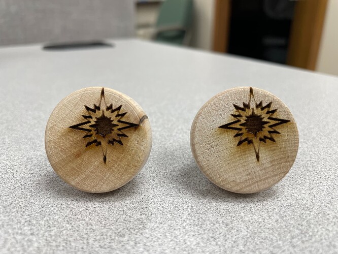
Here is the latest run. I did one, but the engraving still came out “blurry” so I switched back to my old scanning offset adjustment numbers and did another run. This time, the engraves are of good quality and evenly engraved on both sides!

The engraving is still very far off from the center which perplexes me a bit. We run a lot of these coins, so we designed a jig using CAD software and then laser-cut it. By doing this, we know exactly where each coin is when we are engraving them so the design can be centered nicely.

Once we get an image that we would like to engrave, we first bring it into the CAD software tweak it a little, and overlay it on the virtual jig to make sure it will line up well. Then we import that .dxf into LB. So why are the engraves so far off?

See what painstaking inspection & repair can accomplish? :grin:

Re-doing the Scanning Offset Adjustment measurements will be beneficial, now that the beam is actually coming down to a point on the material and not splashing off the nozzle.

Well, you know where the jig sits, but the controller must also know where it is.

It’s entirely possible the original jig placement depended on the original janky machinery setup: that was then and this is now.

If I understand correctly, the “virtual jig” is in the CAD software, not LightBurn, so its position in the LightBurn workspace may not be fixed.

Would it be feasible to import the jig into LightBurn once, align it to the physical jig on the platform once, then import the day’s coin crop into LightBurn, snap them to the jig, and Fire The Laser?

This could be as simple as dragging the imported virtual jig / template to match up with the physical jig on the platform.

Put crosshair targets in the four corner pockets of the template, put four cardboard dummy disks in the corner pockets of the jig, then:

  • Click to Move to a target center point
  • Fire The Laser to mark that spot on the disk, probably not at its center
  • Nudge the whole template on the LightBurn Workspace to move its center closer to the physical center
  • Iterate until pulsing at the target center hits the disk center
  • Verify the other three corners

Then lock the template in place so you can’t accidentally move it while mousing around, save that file, and you’re good to go. Assuming, that is, the machine homes dependably every time it starts up.

Or, more likely, I don’t understand how your work progresses, in which case none of that will make sense … :slightly_smiling_face:

Yep, you’re right. The offset numbers needed a lot of tweaking. I was excited to try the engrave again figuring that retuning these numbers may solve the low-quality lines I have been experiencing. Unfortunately, the results were worse.


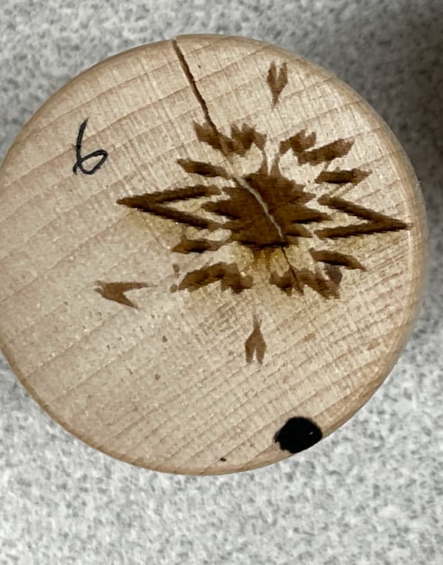
This is not the exact part, but the results were similar to this with “blurry” lines.
I am trying to think if I changed anything major on the machine at some point to counteract problems that were due to the laser not being aligned…but I can’t come up with anything.

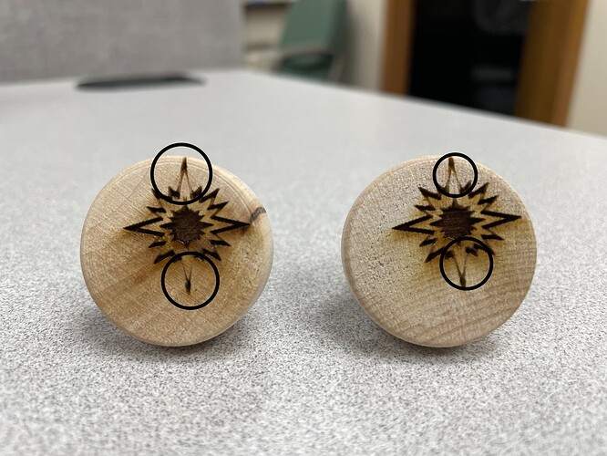
If the photo is oriented as it was engraved, then it’s worse than blurry: the pattern is straight-up broken.

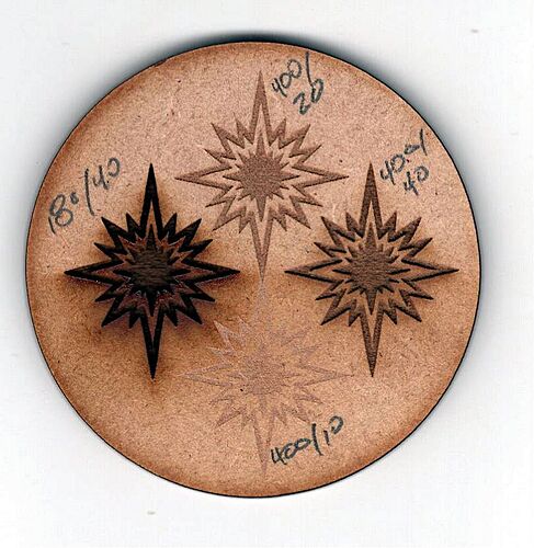
This happens on a scrap of MDF using the file you uploaded much earlier:

The one on the left has your original settings, which are way hot here, and the others are faster & lighter. What’s important: all have the same shape as the digital design, with no broken tips or scattered pieces.

Given the way you described your process, I assume you sent the file to the Ruida controller long ago, then select that file and run it using the console. If that’s the case, perhaps the file was damaged in transit, because all of the results look exactly the same, with the same broken pieces in the same places every time.

The usual advice applies: Delete all the files stored on the controller, because Ruida controllers go nuts when they run short of memory. Then send the file again and see if the results look different than what you’ve shown.

If it’s still broken, but differently, then we get to look at the connection between the PC and the Ruida. Ethernet is greatly preferred, USB generally introduces all manner of jank, and both can have subtle gotchas.

I forgot I shared the file a while back and was very confused how you had my file haha. The speeds you show are incredible to me. I have it at 180 and am still struggling to get some detail in it.

Yes I send the file to the Ruida over the internet. Although I update it frequently since I do minor changes to the file. I’ll take a look and see what I get.

Also, thanks very much for the help so far. This goes for @jkwilborn as well. It is much appreciated.

If they’re both plugged into the LAN, then be very sure the router cannot assign the Ruida’s IP address to another device through DHCP. When that happens, both devices will respond to network traffic to their (duplicated) IP address, which will trash the data going to both of them.

The Ruida has very little error checking and tends to store damaged files without complaint or comment. Worse, the errors aren’t reproducible; the only hint is that a file stored in the Ruida will produce the same errors in the laser pattern every time.

More discussion:

Yep, a damaged file must’ve been the culprit. I wiped the Ruida, and resent the file, and it turned out just fine (well, as good as it has been).

I also unplugged the Ruida and pinged the IP address as recommended in one of the threads you shared, and I got nothing back. So I am fairly confident nothing else is on that IP address.

As far as my faded lines go on the engraves. Do you have any other ideas? I was really hoping the scanning offset adjustments would’ve improved those but no luck.

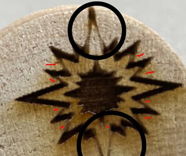
This isn’t just on those two end, quickly marked all of the areas. You can see the failures on the top/bottom tips of the inner image… thanks @ednisley for running the job for us.

:smile_cat:

Yep you’re right. I hadn’t noticed those. And now looking closer, the inner star has some faded areas on it as well. Perhaps I should try recalibrating my steps for my X and Y axis?

I doubt re-calibration will do much … I need to think on this…

It appears to only happen when it’s at those angles… but if you look close, you can see aberrations around the center lower image in the same areas as the failures. Might be related, but doesn’t seem to appear higher up in the image.

The center image isn’t as consistent as I’d expect, irreverent of the surrounding failures.

I’d think it would be something other than calibration… I can’t image them being off enough to really cause any kind of computational speed error large enough to create these results.

it also is not on just the angled fill areas …

Thinking …

:smile_cat:

Okay so I just realized something. At some point yesterday, I must’ve switched back to my old scanning offset adjustment numbers from a long time ago. The good quality I got was with those numbers. Switching back to my most recent offset numbers results in the “fuzzy” lines again.

And just to confirm it wasn’t a corrupted file, I ran the file once, wiped the memory, sent a new file, and then ran it again. Both times it came out bad.

So why is there a disconnect between the lines that I do in the offset adjustment tests, and my actual results? I swore I read a topic about this exact problem but now I can’t find it.

Perhaps it has something to do with how I got the numbers. When I first made the scanning offset numbers long ago, I missed the important part about taking half of the measured value. Those numbers were probably off a little bit. But after I got everything mechanically tuned recently, I modified those numbers. However, I did not do it by measuring the lines in the rectangle. Instead, I eyeballed them and got them fairly close. I’m not sure if this is the culprit, but I figured I should mention it.

That tells you nothing is assigned to that IP address now, but does not preclude the router doing so later when a new device pops up on the network and asks for an address.

How you fence off the laser’s static IP depends on which router you have, but if a file got trashed on the way to the laser once, it will certainly happen again and it will be well worth your while to avoid that particular heartache & confusion.

NO!!!

That controls only the distance traveled and has nothing to do with the material damage inflicted by the laser.

If the machine moves 100 mm for a 100 mm command, then it’s calibrated. If it does not, then tell us all about it.

I’m having difficulty keeping up with your flailing around here.

Now that we’ve gotten rid of the damaged file that has been confusing things since the top of this thread, start from scratch by turning off the Scanning Offset Adjustment, running that test pattern I sent you, measuring the line offsets (buy yourself a measuring magnifier), dividing by two (:heavy_division_sign: 2), and filling in the table again. Start with the usual positive values, enable the adjustment, run the test pattern again, and maybe we can make some progress.

Please keep it simple and change only one thing at a time, OK?

OK, I have an update.

After totally removing my scanning offset adjustments and redoing them as @ednisley recommended, I reran the parts. The same issue occurred.

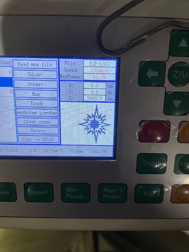
But the talk about the Wifi problem got me thinking. So I looked into it a little bit. I pinged the machine and was getting a slight amount of packet loss, so I changed the IP address of the machine. I then sent a file to the machine, and it was broken. In fact, I could see that it was broken on the screen. So I connected to the machine via a wired connection and sent a file and it was still broken! I tested multiple files to ensure that it wasn’t the file I was using, and they all had similar results.

Here are some photos of the RMI and some notes on each:
As you can tell, this file is intact. But the actual engraving is very distorted and missing parts altogether.


I then realized I hadn’t turned on Scanning offset adjustment numbers (since this was a “new” machine due to me using a wired connection), so I turned those on. Now this not only looks broken, but it also engraves very poorly.

Then, just for fun, I changed the line interval to 0.1 (it was at 0.8) and slightly reduced the speed. I sent this new file, and got this:

This one also engraved similarly.
Suffice it to say I now better understand what was going on before but am slightly more confused. :rofl:

P.S. The image now engraved in the center of the coin as well, so I will chock that up to the broken file transfer via wifi.

OK, this basically the root of the whole mess. Nothing else matters until you fix this.

Whether the machine uses WiFi or a hardwired connection, its IP address must not be double-assigned by the router. You need to figure out how to check the router’s DHCP settings, find the range it’s using, and assign the laser address outside that range.

If the laser’s address is 192.168.1.xxx, then the router’s web management page is typically at 192.168.1.1. Poke around and report back what you can find.

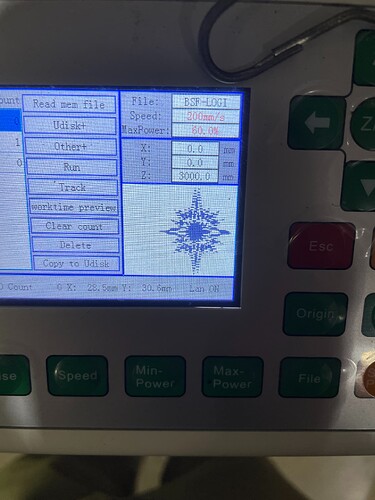
It should, because the console display shows what the laser will be doing based on the instructions, not the result on the material after going through the power supply and tube: the display does not know about the timing adjustments.

However, the size of the offsets suggests an error either measuring the scanning offset or entering in the table, because the values should be on the order of a few tenths of a millimeter, not a few millimeters.

Concentrate on getting the IP address sorted out and solving the file transfer problems.

1 Like

I’ve decided to make a new post about the broken file since I felt it was confusing me enough to warrant its own🤣

Thanks all for the help though.

This topic was automatically closed 30 days after the last reply. New replies are no longer allowed.