Exactly… As I could only apply the kerf to closed objects, I used the ‘full kerf’ on the ones that mated…

Exactly… As I could only apply the kerf to closed objects, I used the ‘full kerf’ on the ones that mated…
Feel free to move/merge this if it goes elsewhere …
Reading the above answered most of my questions, but I have a couple more…
With regard to finished part size, kerf, and axis calibration, it seems to me that one should do a kerf test first, apply the necessary kerf offset, run another part, then measure and apply any necessary changes to steps/distance.
Is this correct?
With regard to non-round laser spots producing variable kerf widths depending on cut direction. We are limited to single kerf offset (per layer). How is stepper/axis calibration affected by this? Can/should we attempt to compensate? If so, how best to approach?
That will give a size change proportional to the object’s size: the larger the object, the bigger (or smaller) it will become. This is, in general, not how a kerf behaves, because the cut width remains the same no matter how large (or small) the object you’re cutting.
Set the step/mm or mm/step to get the correct size, as measured with the aiming dot on a good scale / ruler / tape, so that the nominal size / distance in your design produces the correct physical motion:
With that in hand, you can measure the actual kerf width, apply that to any size object, and get the correct physical size.
Good idea! I’m coming from 3D printers and automatically think print, measure, adjust steps. Never even crossed my mind to just use the laser and scale. Lol.
I don’t understand why you would do anything else but cut and measure. Just cut a 20mm square, if it measures 19.4mm, that is the kerf of two sides so you’d enter 0.3mm.
I have found teaching others about the automated kerf mechanism to be a bit problematic.
There is nothing “wrong” with LB’s implementation per se. It’s not a bug. The problems I saw users run into was that 1) they weren’t strict about making sure they actually had closed shapes. They’d been cutting successfully so far just thinking lines were lines. Lines crossing, or even having shared vertices, do not guarantee a closed shape. 2) LB will do the “correct” thing and alternates the direction of the kerf. e.g. if you cut a rectangle with screw holes in it. You’d give it a positive kerf in layers. The rectangle’s sides swell outward, but the screw holes will do the correct thing and go negative and shrink inward, yielding the final dimensions the design asks for. But if the user says “well, I’m going to do this better and do the outside on another layer” and cut the screw holes without the outer perimeter, then the kerf flips.
User error, sure. But I do suggest that they may want to try Offset Shapes by the same amount, as it does the same thing. You should be able to see if you didn’t get a kerf because the shapes weren’t closed, or it’s signed the wrong way.
I could imagine in a perfect world, LB might overlay a faint dotted line to show where the kerf offset line is going to cut at in the Preview window, alongside the solid lines as per the user design.
Kerf is not entirely constant. Even with the same material, it does get slightly wider when cutting thicker pieces due to the slower speed. It is also not perfectly vertical.
Having built my own 3D printers, I’m quite familiar with the need to calibrate steps/mm, hence my question about order of operations. You guys running expensive name-brand CO2 machines can probably trust the manufacturer got it right. Us poor souls running budget Chinese diodes should probably verify. LOL.
I’m comfortable cutting, then measuring. I also like the idea of saving the couple bucks of material and just using a scale. It also eliminates one variable. Another benefit of the scale for me is the ability to use the entire bed. My biggest calipers only go to 310mm but my bed is 410x750. I just compared my metric tape to the calibrated mitutoyo scale at work and the tape is accurate well beyond 1000mm, so I’m good there. It may take a little trial and error to get right since I can’t accurately estimate fractions of a mm with a tape, but a few adjustments to get me right on the mark eliminates that concern and costs nothing.
Before searching for this topic, I cut a 250mm square to check and measured something like 249.79 x 249.95 and wasn’t sure if I was seeing a error in the stepper calibration or an effect of the kerf…or both…and wanted to see what the best order of ops was to get it dialed in properly. At the time of that test, I hadn’t yet applied any kerf offset.
My laser spot is rectangular. Something in the neighborhood of .15 x .20. I have a crack ruler to measure it but don’t have any anodized aluminum to check it with…just wood…and I don’t believe that’s quite as accurate.
I haven’t yet done the “20 cuts” test to measure cutting kerf.
I want to live in the parallel universe where that is true. ![]()
Wisely is it written: Trust, but verify.
Even there, the slicer knows how far to inset the perimeter, because it knows the thread width. If, of course, you’ve painstakingly calibrated the Extrusion Multiplier properly so the actual thread width matches the nominal width.
Fiddling with the Step/mm can get you close for a single model, but will introduce scaling errors for any other model. Fortunately, 3D printer platforms are so small and the structure so bendy that “getting close” is about as good as you can do.
Adjusting for kerf/offset is not a machine calibration issue… it is a CAM/Slicer issue.
Machine calibration is a characteristic of the machine itself. Each machine axis must move the exact amount commanded… and the steps/mm to accomplish that is GOLDEN, once determined for that machine. You do not determine steps/mm by printing/cutting and then measuring something. You determine it by measuring the actual axis movement when commanded to move a specific amount and, once it does, leave it alone. Use your CAM/Slicer software then to adjust for any tool you mount on your calibrated machine.
As Ed said above…
and, in reality, all you are doing is UN-calibrating your machine.
Everything I’m hearing is to avoid using the axis calibration (or doing the math and adjusting manually). I know from experience the steps/mm can be off from the factory, or because of various hardware changes. I’m going to check mine this weekend. Perhaps it will be fine. Perhaps not. My machine is no longer stock config. It has a Y axis extension, so who knows.
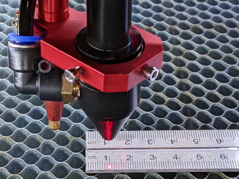
It is very simple to adjust the steps/mm to get precise movement of the axis. You can use the laser if already mounted… but I’m often building a new machine before any tool is mounted. So as soon as I can move an axis under power – and it moves consistently/repeatably the same amount (even if wrong) when commanded to do so – I like to rubber-band a wooden skewer (or other pointed object) to my tool mount, lay a ruler on the work surface in line with the axis, and lower the skewer point to a point as close as possible (without touching) above a major division on the ruler. Then enter a gcode command from the console to move a safe amount (start small… say 50mm, 100mm, etc) and observe where the skewer tip moves relative to the ruler’s scale.
For example, if you commanded 100mm and actually only moved 98mm and your current steps/mm setting is 80… that setting needs to be increased to add enough steps to make up the 2mm it fell short. Use the following to determine the new steps/mm setting…
(Commanded movement / actual movement) * current steps/mm setting
so, plugging in the values… (100/98) * 80 = 1.02040816327 * 80 = 81.63
Adjust the steps/mm setting to 81.63 and rerun the test… you should see very close to 100mm actual movement for a 100mm commanded move. You can do this as many times as you need to… and greater accuracy will be gained with as large a movement as your axis will allow.
I often print/engrave rulers with my machines and then visually compare them to a good metal ruler to see how well I’ve done. It’s very satisfying to know that 1" is really 1" on all the machines in my shop.
– David
Thanks for the math…
I thought I’d link the @BillieRuben post on the keft gauge she created… Pretty slick.
![]()
You’re so lovely, thank you! <3