When they import properly, what do you get? Not the original vector…?
I never got an error, but also nothing visual.
![]()
When they import properly, what do you get? Not the original vector…?
I never got an error, but also nothing visual.
![]()
Line 21 has a z10
You could use [CNCJS].(Release v1.10.3 · cncjs/cncjs · GitHub)
Has a 3D view.
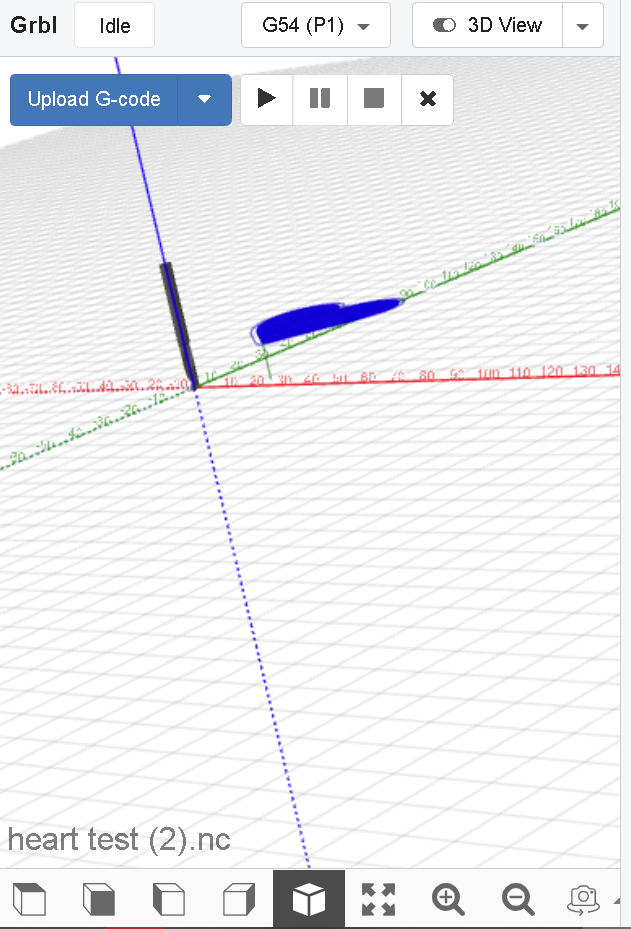
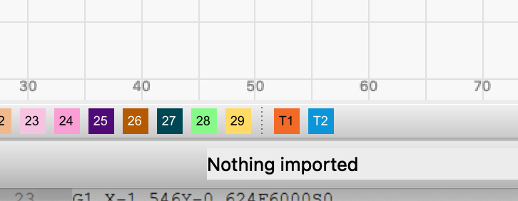
“nothing imported”, that’s what I get at the bottom of the LB window
May not have looked down there… ![]()
![]()
Thanks for the tip, but outside of LightBurn it can be difficult to find the problem that specifically affects LightBurn.
The same for me in Lightburn so I used cncjs.
I don’t know why the Z movement exists, since it has the values set to zero.
But on line 23 it moves to 10.
It’s interesting and suggests something is wrong with the controller, especially when all projects end up like this.
Edited file with Notepad++ and removed line 21.
Test this file and chek if it works.
hearttest (1).nc (60.4 KB)
However, I tried to import hearttest (1).nc (edited) into Lightburn 1.4.05 and it didn’t work either.
strange
Hi Bernd,
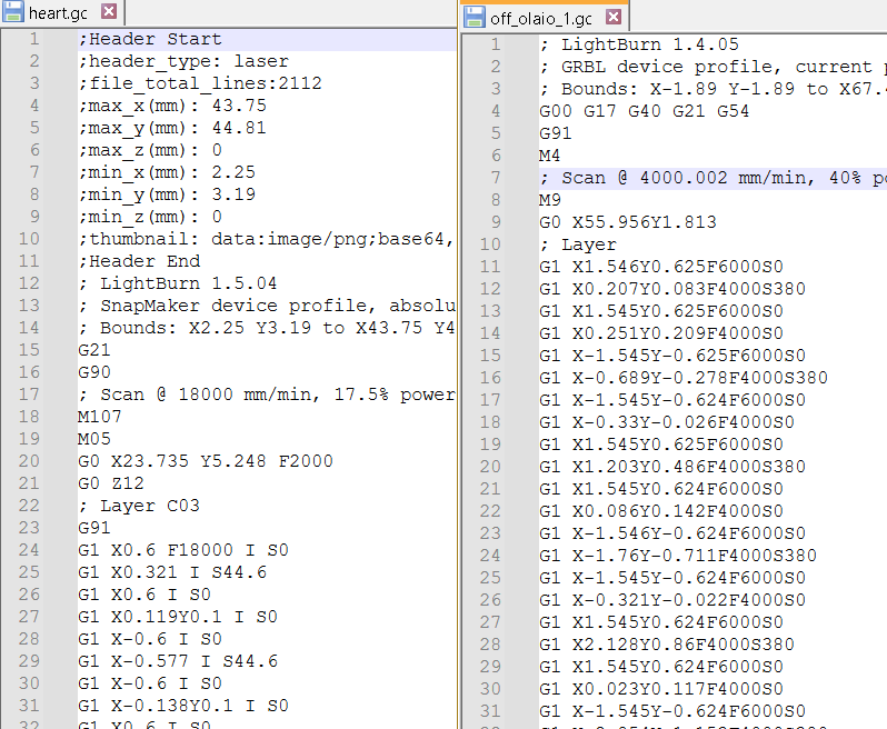
So I could only save a gcode and manually changed the file to an .nc as the Snapmaker only accepts .nc not .gc. Here is the gcode and the lightburn file
heart.gc (60.4 KB)
heart.lbrn2 (51.8 KB)
e
I’m a bit rusty with GCODE, but the start of the files is different and this time Z is moving by 12.
I haven’t worked with g-code since my 3040 china milling machine time with Mach3 … ![]()
If the machine has autofocus or is set to gradual lower function, it could be an explanation for the Z Axse G-code, but the difference of location from text and Shapes should not be a result of it.
There is nothing wrong to see when I open your file (LBRN2), so I’m a little out in deep water here.
The .gf file does not open either.
It’s so annoying, what could it be? I really want it to work and neither Snapmaker or Lightburn seem to be able to help either
I saved the heart.lbrn2 in gcode and compared it with the heart.gc. I’ve set my Lightburn to absolute coordinates and the coordinates values match. The differences I found in the heart.gc were a G21 (millimeters) and an I before the Ss.
But isn’t the work being done in millimeters or is there a “conversion”?
Also when cutting, does S=255 correspond to the maximum in Snapmaker?
Alright, a lot to unpack and sorry if I’ve missed a few things.
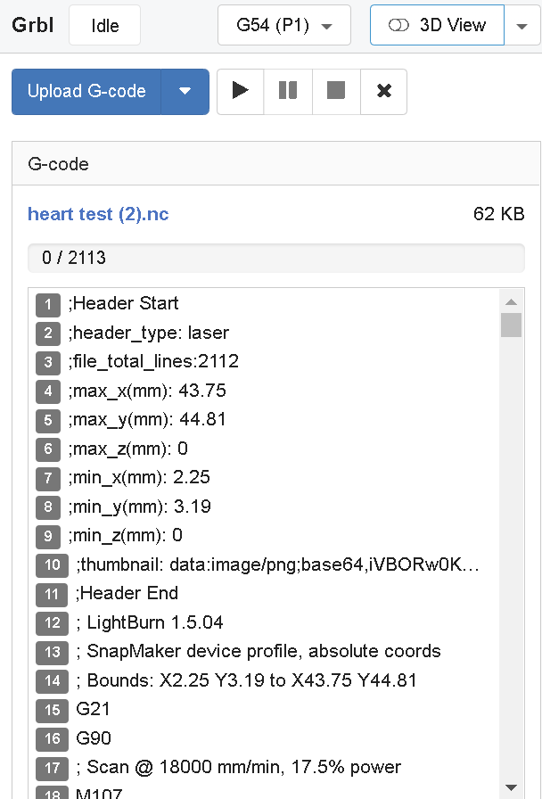
One problem you have (looking at the original heart test.nc) is the fact you have the speed waaaay too high. This might be causing the steppers in the modules to lose steps between scan/cut. Especially with the weight of such a large laser unit.
; Scan @ 18000 mm/min, 17.5% power
The 2.0 realistically can travel 9000mm/min with the new rails and 6000mm/min with the old rails.
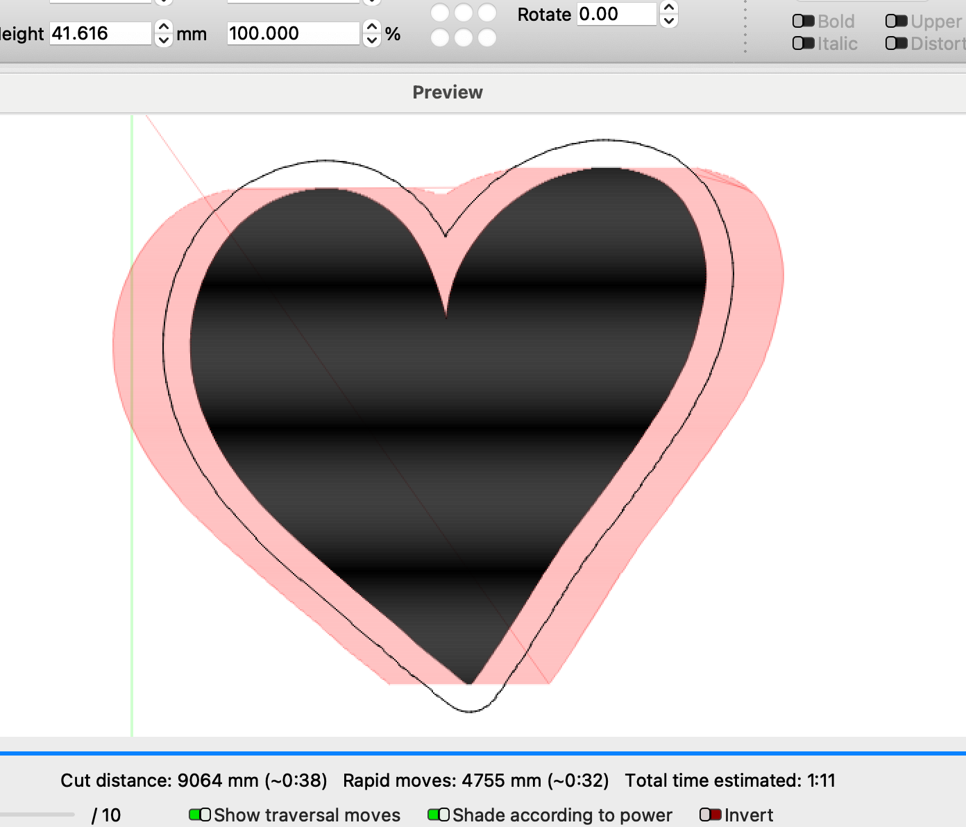
Also I noticed between the scan and cut it uses relative position (G91) for the fill scan, but uses absolute (G90) for the cut. Which is sort of odd to do it that way, but should be fine. A test on my own machine with the latest firmware (1.19.0) runs fine. However, I only have the 10W and not the 20/40W.
Another thing you can try is change the machine type to GRBL-M3 (click “devices” > click your snapmaker > Edit > select GRBL-M3 in the controller list and then OK through everything) and then try one of your test files again.
EDIT: Also testing your heart.lbrn2 file (reducing the speed/power) worked fine for me as well, and I noted you had 2 as the material height, but your matching .nc had a G0 Z12 make sure you don’t have a Z offset in the layer settings. Make sure to zero out “focus height”, my bad.
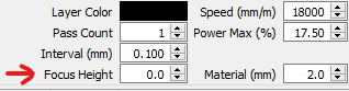
Just for general information, is the Z movement normal on the Snapmaker or is it autofocus or something else?
They likely have 10mm in the focus height box, I’ve seen that one before on the snapmaker forum. ![]()