I am losing steps trying to line the borders of very small letters, to the point of being off by 3 to 6mm after just 200 words. I have tried to decrease the speed and acceleration to near unusable levels, with little change. Would it be worth it to try increasing the voltage to my stepper motors?
Running OMTech 50W machine. I can’t find any markings on the stepper motors. Would it be safe to assume NEMA 17?
How exactly would I go about changing the voltage?
Do you know the voltage? Do you know the stepper driver resolution? Nema17 is a good assumption.
Adjusting current is easier but could heat up the steppers.
It appears to be a NEMA23 base on the size of the face plate. It appears to be a 57mm x 56mm size.
They do not seem to be overly hot, so adjusting current could be worth a try.
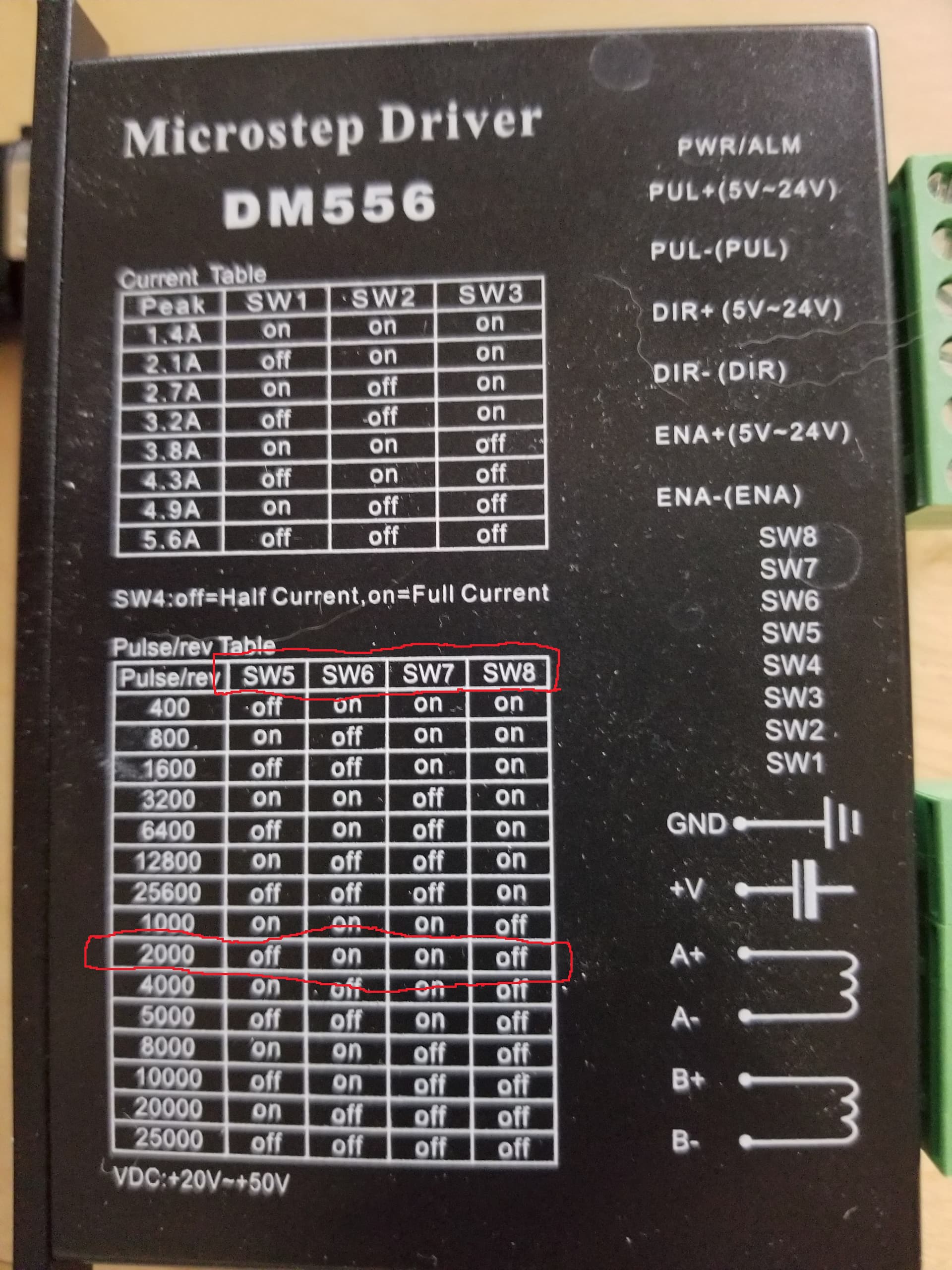
For starters I would assume the driver switches are set up correctly, unless you think someone messed with them. Per Jacks image you should be able to determine what they are.
Your seeing movement. Did you see a change in the origin after the run? Meaning set some zero then check to see if it moved. If so are all the connections from stepper to pulleys all solid? Belts are tight?
The origin is most certainly moving. Through the run it is gradually moving. If I start a new batch they start from a new place. Usually 3 to 6mm in the positive x direction. However I am not hearing loud sounds necessarily. I am open to the possibility of other issues.
The belts are tight. The pulleys are very hard to access so I’m not sure but two reasons I don’t feel they are the issue: 1. The gantry etc are rock solid if I try to move them while the machine is idle. 2:Not having backlash issues that I can not fix with scanning offset adjustment.
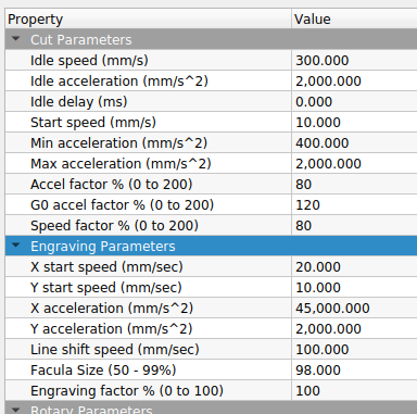
I have tried acceleration rates as slow as 400mm/s2 max. I have also tried speeds as slow as 12mm/s. Unless I combine those bottom most speeds and acceleration rates, the problem seems unchanged. The end result is at least 3mm difference in origin. This is after just an 8 minute job. Even at those low acceleration and 15mm/second the problem persists.
I believe I have not yet played with jumpoff speed. Would you be able to explain what that does?
Sometimes doing mugs, I have the acceleration values down to single digits…
Maybe a picture would help us visualize what you are up to.
If it’s not an issue, can you post the .lbrn2 file so we can get a better idea of exactly what you are doing and how you are doing it…
Since you are loosing small amount of steps, it may not be much of a change in sounds especially if you are vector cutting.
I have no idea if this would help, but you can change if the motor acts on the rising or falling edge of the signal from the controller. Although I would have thought you would have seen this in other issues.
I’m kind of grasping at straws… This is what I’m referring…
I don’t think your loosing steps because it’s too consistent, but you could try increasing current.
I have a similar issue on a router when using a UC100 controller on dual Y steppers I noticed after a couple minutes of cutting that the machine became racked. I put tape on both steppers and proved that they were out of sync by over a revolution over the entire cut. Switched motors and it followed. Concluded that it was from a low cost USB controller.
So large step loss is much easier to solve then small path error.
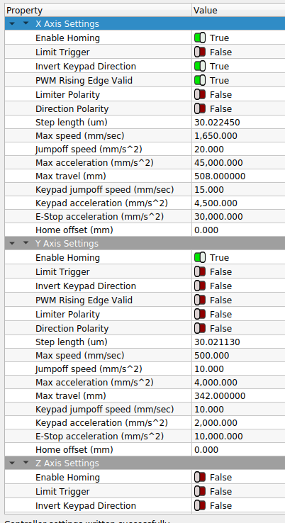
I will attach the file here. The actual file has a lot more to it but I have isolated the issue to what is left in this example file. All the other parts do not seem to cause this issue.
Yes, PWM Rising Edge setting was one of the first things I tried, but it has been a while and I have made other changes since. I’ll go back and try switching it each way again just in case.
Can’t hurt to try changing current right? Would you happen to know any helpful posts or info about changing current? I’m having trouble finding something that explains exactly how to do this without damaging anything. Not sure where to get started really.
You have to look at the data sheet for the motor you have. The motor driver is usually where the current is set and that varies with the driver. Some you have a wide selection and some are full current/half current.
They will heat up.
Look at your motor driver boards to see how they can be configured. Usually they have a ID of some kind. Mine are DM545’s I think…
What’s your budget? Closed loop stepper motors are a great upgrade and not all that expensive anymore:
One difficulty is the encoder wiring is a second cable, somewhat thicker, and you pretty much surely want to use the OEM cable and extender cables. This may be difficult to fit into the drag chain going from Y to X specifically. Also, the cable end is bulky and of course nonremovable, so if it doesn’t fit through existing openings you’ve got a prob. Such as drag chain with non-openable links- you’d probably replace the drag chain
When I looked at servos and the expense, I didn’t find closed loop drivers at that time. I’m guess they are about 2 or three times more expensive. I know they can tell when it loses ‘steps’, but I don’t know what the user can do if it does fail.
The leads to the motor is only 270mm (10") so both the of the ‘big feedback’ connectors and motor field connector would be ‘inside’ the drag chain. At least for the X axes on my machine.
I spent a lot of time and money to do away with the drag chain/mass on the X axes. I don’t think I’d like to add more than I have on the Y and slow it down. I know those connectors would not work (too big) without some major modifications to the Y drag chain.
Closed loop drives are MUCH smaller than their open loop equivalents. And actually reasonably cheap. The motor is longer and OMC-Stepperonline datasheets of “length” do NOT include the mandatory encoder on the end which is weird.
Closed loop encoders commonly resolve to 4000 counts/rev. The drive handles the multiplier, you have DIP switches or better yet just program and tune them with the PC software.
The drive makes a very smooth movement with no vibration even if it’s not microstepped.
Closed loop does not “stall” like conventional steppers. The drive may or may not allow the rotor to get a certain amount out of sync, which it will eventually “catch up”. I tried to push the rastering acceleration to extremes, and realized that at a point it would suddenly have a huge “backlash” of like tens of mm because it couldn’t keep the carriage location up.
Or you can configure for going into a fault state as soon as any step lag occurs.
Closed loop drives can run at much lower power when the motor is at rest and nothing’s creating a torque force on the shaft. It doesn’t need current and would instantly provide current to resist a force that made the encoder step 1/4000th of a rotation.
Sounds very interesting. Didn’t remember they recovered on their own. I think I was wondering, as a programmer, I’d like to know it was off a bit. I guess there isn’t a real way to get the error back to the controller in some sort of useful way, as in ‘not halting’…
Tech is moving so fast today… 3 decades ago I couldn’t keep up with it…
You can program the drive to do a lot of things. There’s a “PENDING” output that can strobe when the drive exceeds a sync threshold, but not the ALARM threshold. So a system controller can flag it while tuning without halting the whole system.
As part of the system controller, I do watch ALARM pins. If anything jams an axis and faults the drive, I just disable the door interlock so the Ruida immediately halts and won’t run until power is cycled.
Budget is not an issue with these. However, I’m still not sure missed steps are the real problem.
Also, the objective is to get up and running as quickly as possible. How straightforward is the setup if I would like it to “catch up” for missed steps?
Also, how would you compare the performance to hybrid-servo motors just out of curiosity?
Setup is pretty straightforward. You can set DIP switches if you like, but I’d recommend you just get a cable. It’s just an RS232 to RJ12 cable, they sell them on Amazon, but since RS232 is rare now, I’d get an FTDI USB-to-RS232 cable (genuine RS232 levels) and program it. You can get more out of it that way- for one, DIP switches only have a few currents so your motor probably won’t match.
Closed loop motors provide notably higher performance in the upper speed range where normal steppers start to roll off on the torque they can provide without stalling.
They’re quite smooth.
I don’t know what the default is for the allowable pulses of error, but like I say just program it.