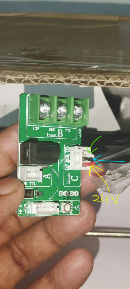
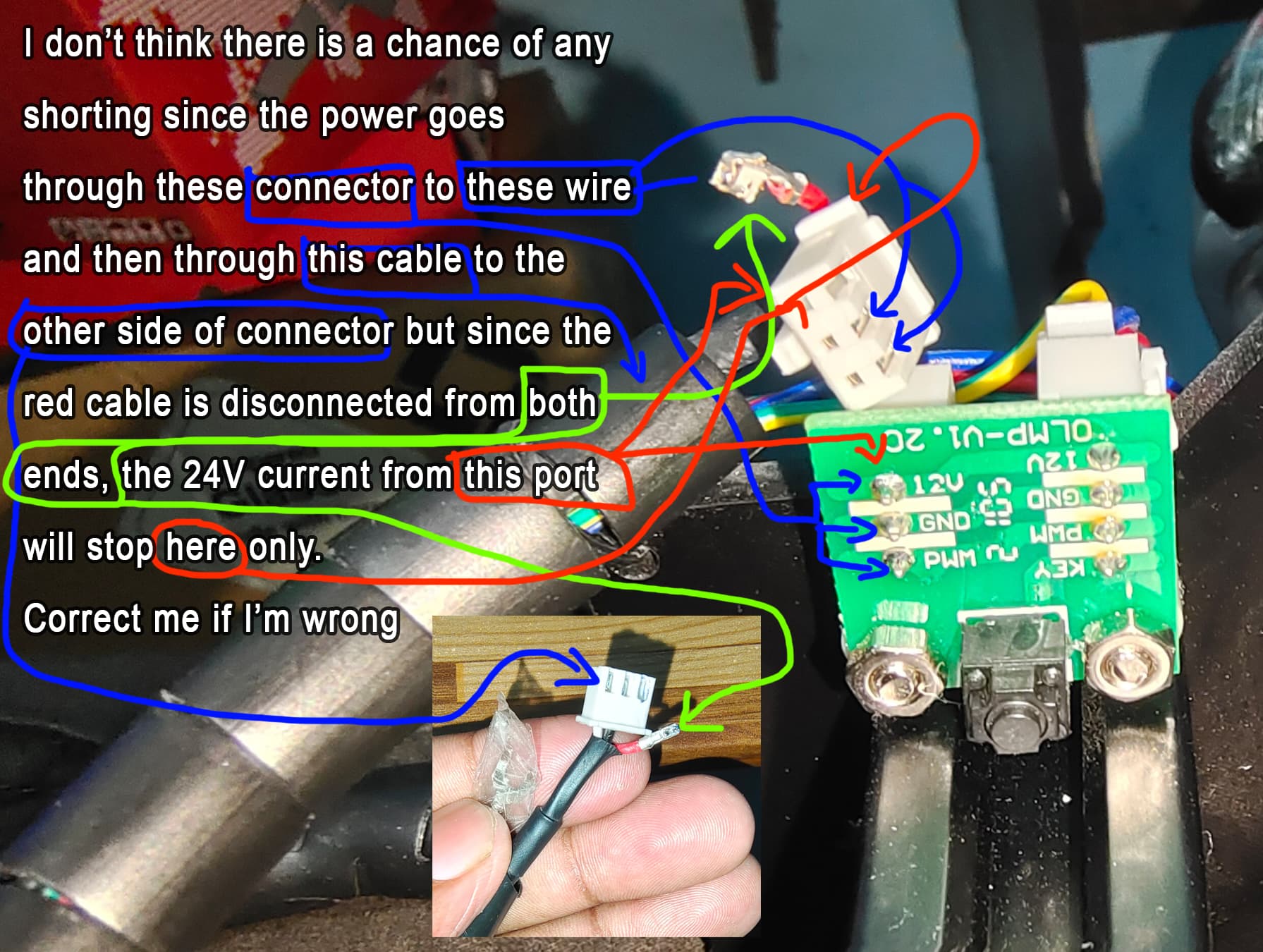
So the yellow marked(red wire) is 24V coming from ortur , blue marked(black wire) is ground wire and green marked(white wire) is PWM/TTL , am I right sir ?
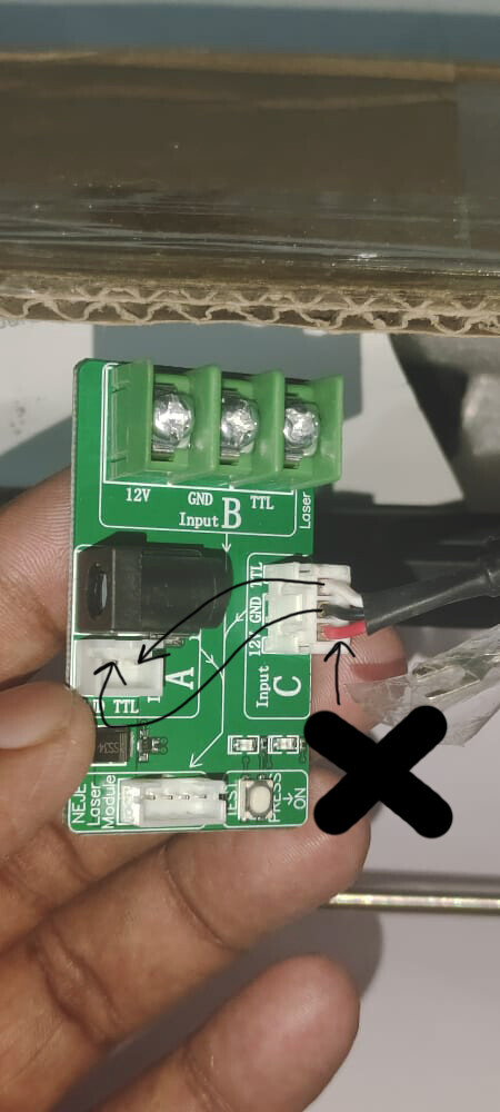
If yes, then I should connect only blue and green marked wire to their respective slots and exclude the red wire and then connect the 12V 2A adapter directly to the board and this should make the machine and laser work , right ?
Also, just curious to know that what if I connect only TTL/PWM(white wire) to this board ? Will it still work ? Actually I don’t know the working and role of ground wire so that’s why asking!
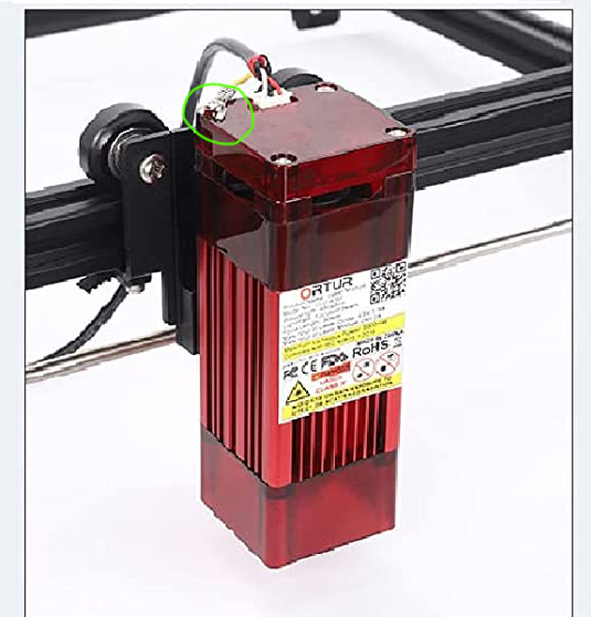
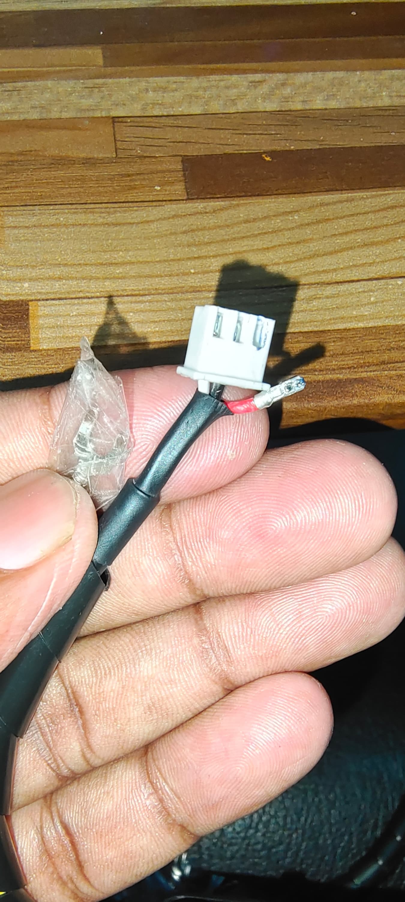
Also there is a seperate fork shaped wire is given(in the above image, above the text 24V, enclosed in cello tape) that is to be attached to one of the four screws like this
Most likely, yes. You should actually check those on the Ortur side to make sure what it coming out of the controller matches. Or use a volt meter to check.
Yes. But if you do it this way you really need to do this cleanly. You don’t want a live 24V dangling around. You should remove on both ends of the cable and actually insulate the connector and secure it so it’s not loose or remove that line entirely.
If you can get a dedicated 2-wire connector going to the 2 pins on A then that would be even better.
You will need TTL/PWM and Ground. And that will work fine.
Connect it as it’s shown in the picture. The other side of the wire should be connected on the side of the gantry. This is for bonding the chassis and is necessary for static discharge. You may need to get a separate wire for.
I got an electrician to check that through voltmeter and the volt in black and red wire was 22-24V but I didn’t check the white TTL wire. Should I get it checked as well ?
Sir can you suggest me or send me the link on any such connector ? Since I don’t know even what is it called or even by what name should I search it on google.
And, as I have seen on yt, neje doesn’t use that fork shaped ground wire in their machines but ortur does, and here I’m connecting Neje or ortur, so should I still connect it ?
You don’t need to change connectors or buy a new cable. Use whatever cable you have (in the photo).
Cut both ends of the 12v line, near the connectors, and it will just ‘peel’ off, leaving you with a correctly polarized plug with the proper control lines sans the 12v.
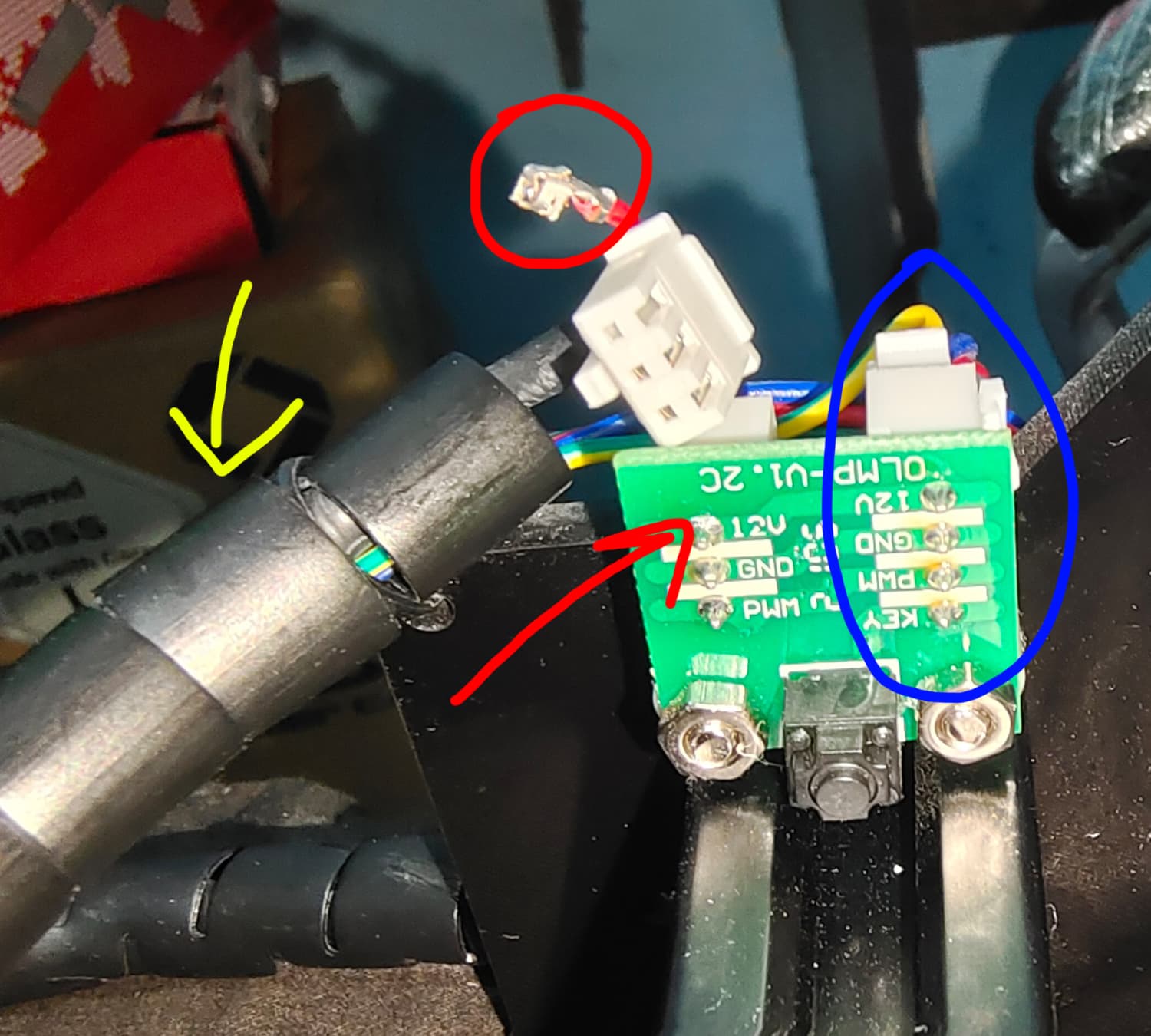
Okay, so I just checked this is the board of ortur and the blue marked cables are connected to the main 24V board where adapter connects and the yellow marked cable goes towards the laser module and I have disconnected the red power carrying cable from both side
Now I guess I don’t need any seperate connector to the connect to that board since I have took out the red cable, right ?
Also, as marked with red arrow, the power written is 12V then why did it show 22-24V in voltmeter ?
He came to check 3 days ago and I didn’t know that it’s 12V mentioned on the board at then. This I checked today only.
But since the adapter was 24V so I thought the voltage is proper. But seeing 12V written on the board I got confused.
Also, I’m not aware much of this voltage current.
Because the Ortur board provides 24V. It doesn’t matter what is written on the laser adapter board. That is just what is expected for that adapter.
Remember, the whole reason you’re in this position is because Ortur is providing 24V. Laser module is expecting 12V. So you put 24V to the expected 12V input. That should keep it straight in your mind.
Yes. But do not leave that wire just dangling there. Either remove it or insulate and secure it so that there’s no chance of a short.
You’re correct in that it’s not actually deliberately connected and is not carrying current. However, as a matter of practice you do not want potentially conductive components, especially ones that are designed for the purpose and so close to other conductive areas, to simply be loosely hanging around. Your machine is going to be moving rapidly and the possibility that the lead happens to simply touch something else is very real.
So either remove the line or insulate the ends and secure it with a zip tie or something so that it’s not loose. Do this for both ends.
Yes sir, I’ll definitely do that. And thank you so very much to you sir and sir @jkwilborn for helping me out and clearing all the things.
Can I have any of your contact like social media or discord ? Incase, in future if I get stuck somewhere, I guess you are the only guys who’ll help me out.
well… i’ve not posted here cause i have seen you were followed by a couple of most skilled users in this forum, so my solution was useless cause i would have told you the same things.
Hello sir, the driver board for laser module has been delivered to me but Neje has not included the fan and I’m assuming that the fan in the module was burnt when I supplied 24V. So can I buy any 12V fan with same dimensions, from local market and connect it ? As ordering from neje will cost me 10$ plus 15-16 days of waiting time.
I’d suggest testing the fan. Fans can often take a wide range of voltages without damage especially if it was not running long.
If it’s actually broken I’m not super familiar with replacements for a laser module but fans are typically rated based on voltage, RPM, PWM, and CFM as well as size. I don’t know if Neje provides these details.