I’ve converted my K40 to Skr 1.3+Smoothieware. All seems to work property but not the power control from the layers.
When I put a layer in “line” or “fill” mode, only works if the power is 100%. If I put 90, 80, etc. the laser current is 0.
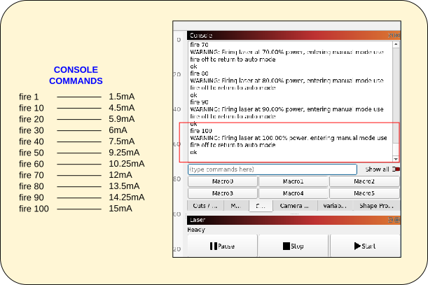
If I send the command fire to the laser, it works perfect. fire 100 is 15 mAmp, and so on.
I don’t know if is something to configure in Ligthburn. I’ve checked all the menus and I can’t find anything.
The L input is active low, most pwm are active high… Don’t know about your specific board… this would not cause the issue you describe…
You should be able to measure the pwm voltage if you have a voltmeter. No need to have the lps running to test this. Run something at 50% and see if you have 2.5V on the meter…
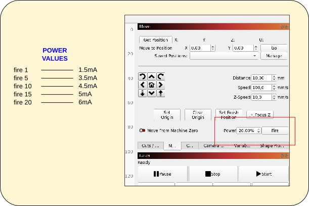
Is important that you understand that I’m able to control laser power from the console (with fire command) and with the laser fire button on Lightburn. In that last case, I’m only able to put up to 20% on the input box (I suppose is’t limited for safety reasons).
So the firmware and Lightburn are able to manage the laser power. Is the value I put on the layer which is not responding. Only 100% is working, below that value the ouput is 0.
Are you able to provide the other things in the list that I requested?
As for the diagram, you’ve abstracted the entirety of the SKR. So you’re showing a high-level theoretical view which isn’t really helpful in diagnosing the issue. In theory your laser should be working but it’s not. Can you provide the specific pins on the SKR or a high quality photo of how you’ve wired the board?
What is USB meant to represent in the diagram and panel? You don’t show the potentiometers in your diagram. How do you have them wired?
I think @jkwilborn’s comment about PWM from most boards being active high is something to consider.
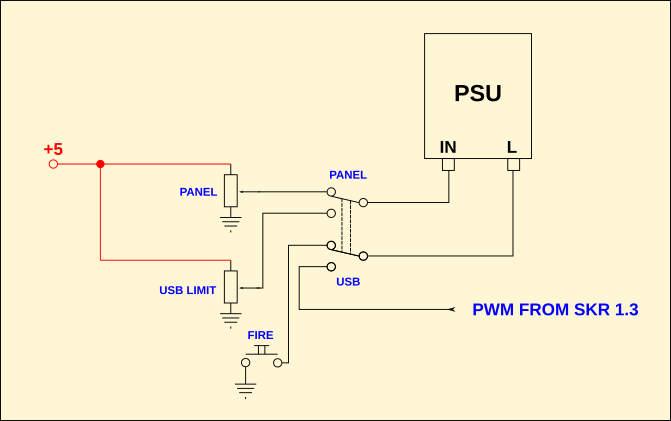
Only one wire is coming from SKR board. The drawing is basically all I have. The ouput I used for PWM on the SKR is the 2.5, the bed temperature mosfet. I have the wire connected to the negative side of the conector. So, when the mosfet goes active, it pulls down to ground the L imput on the laser power supply.
The pots are shown on the diagram. Labeled as PANEL and USB LIMIT.
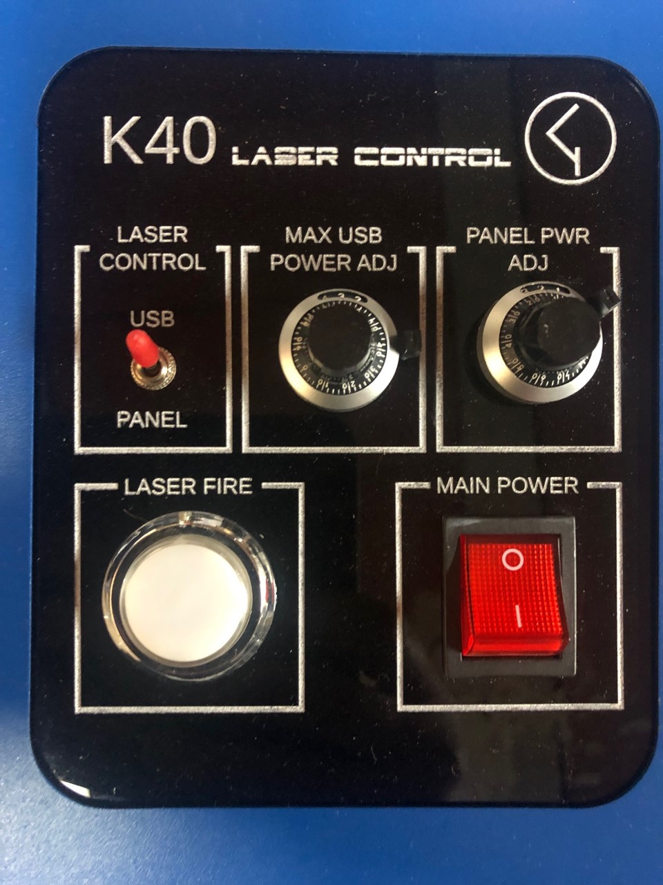
USB means that the power of the laser is controlled fro USB, PANEL from the panel.
I use that pot to limit the max power of the laser at 15mA when 100% is sent from Lightburn.
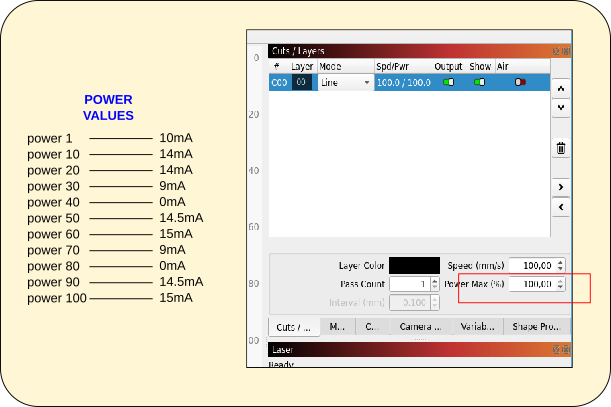
I made a power test from three different control forms. These are the results.
You can see that only values put on the layer are wrong. The rest works like a charm.
You’re trying to control current on both IN and L? I don’t think that’s going to work as you expect. Typically in this type of setup you’d use the POT to control peak current in IN. Then L is only used for PWM to trigger on/off frequency. What you’re doing with “USB” POT is just attenuating the PWM signal.
What is the PWM frequency of this connector? Bed temp frequency is usually quite low. In the Hz range.
I’m not following how you’re doing this. What is the other side connected to? If you are going from ground (what I assume you mean by negative) to any positive lead this is likely to be active high.
I assume Fire command is a smoothieware convention. How are you measuring these currents?
Can you provide the .lbrn file, gcode, and config.txt files please?
Here is a seaming unlikely thread that talks about a couple of issues with the lps control… I don’t think this is the issue, but could be contributing.
They do state “A level converter on the PWM input at the PSU was not necessary because on 2.75V on average the laser reached 18mA (the max you should go).” which I totally disagree with… one argument is that the IN lps input expect a 0 to 5V ttl type signal… it can also take a 0 to 5V analog voltage. 2.75V is not adequate.
Since it is an average… for a meter to read 18mA at 50% pwm, the peak current (on time) has to be 18mA x (100/50) or 2 times the meter reading. Meaning it’s actually drawing 36mA when it lases …
Without some kind of schematic on how it’s configured and how it’s wired, I don’t know what else to suggest… The schematic, which isn’t, is totally useless as @berainlb has mentioned.
You have two ways to control the lps, they are the IN and the L inputs.
One of them MUST be controlled by the computer … unless you want us to believe you can adjust your controls at the front panel that quickly…
Draw a box, set to “Line” mode and click the ‘Save GCode’ button instead of ‘Start’. Attach the resulting GCode as a text file here so we can take a look.
Where did you get your build of Smoothieware from? It needs to be built with “CNC” mode enabled for it to work correctly. (It’s been so long that I can’t recall why this is true, but it is)
What I draw is exactly what I have. Maybe is useless for you, but it is as it is.
Hi,
I didn’t thing to do that, shame on me. Attached is a txt file
with the GCODE of a 20mm square in ten different power values.
I don’t know too much about GCODE. The values of the first G1 are a little weird to me, but I’m not sure if they are correct or not. square_20_20_GCODE.txt (3.8 KB)
I think I take the firmware from the Smoothieware github. I think it was CNC version. the file is now renamed and I’m not sure. Tomorrow I try to find a CNC version and I will re-flash the board to see if anything changes.
Did you initially create a GCode device and then change it to Smoothieware later? Your “S” parameters are scaled in a way that shouldn’t be possible, since Smoothieware only uses S values from 0.0 to 1.0, and I think the only way for this to happen is if you created a device that had a different S_Scale setting, then changed it to Smoothieware.
If you delete your laser and re-add it, choosing Smoothieware as the type the first time, it won’t happen again. I’ve also found the spot in the code where the logic fails to force this and changed it so it won’t happen again.
When I did install the board, I had a connection problem. None of the drives work. In fact, firs time I powered the laser and hit the button “Find My Laser”, It was recognised as “GRBL-M3 (1.1e or earlier)”. But it stays at Busy all the time. Changed to Smoothieware and remains in connecting forever… and is true that I tried all the single drivers… Finally, updating my Linux distribution the problem was solved.
Now GCODE generated is scaled from 0 to 1.
Maybe this button is sending fire commands to the firmware? Those commands works properly.