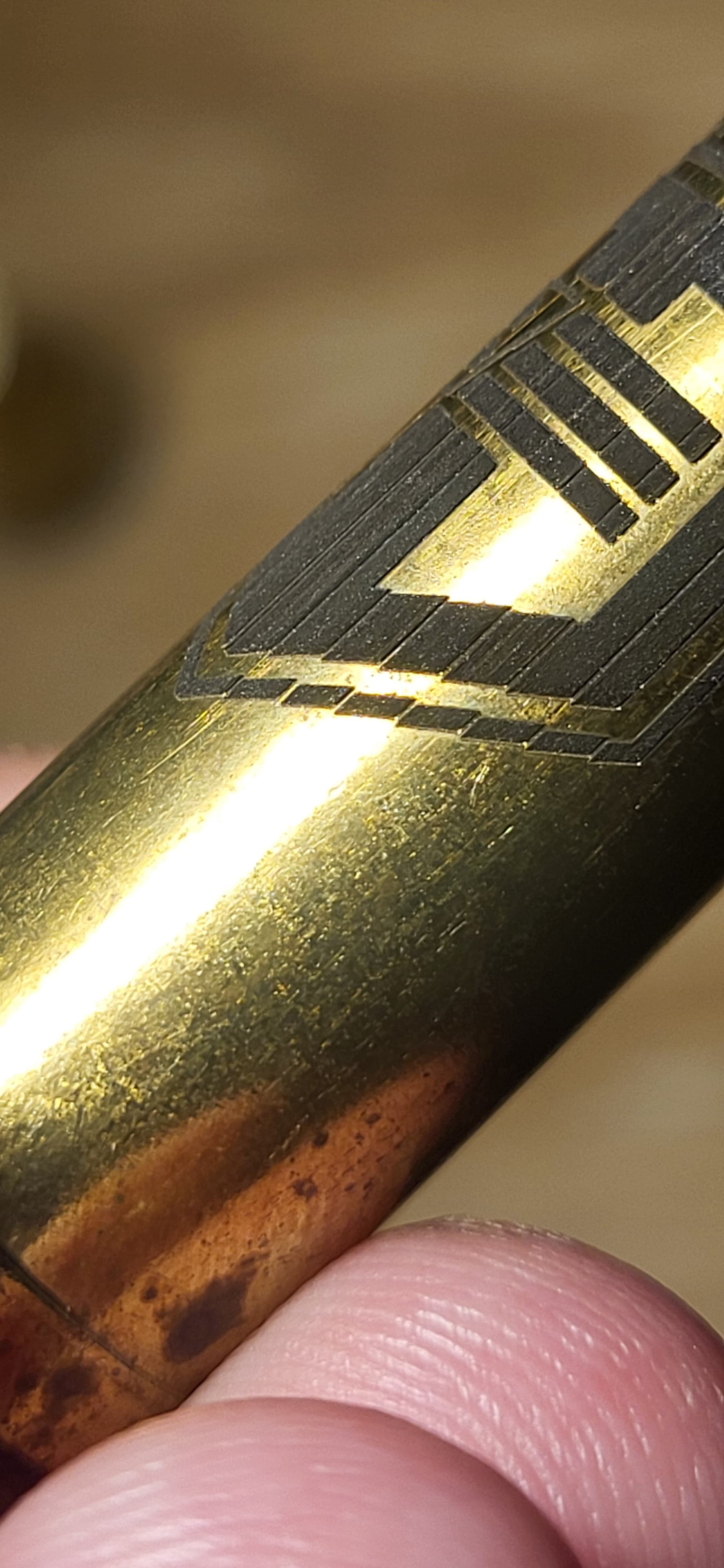
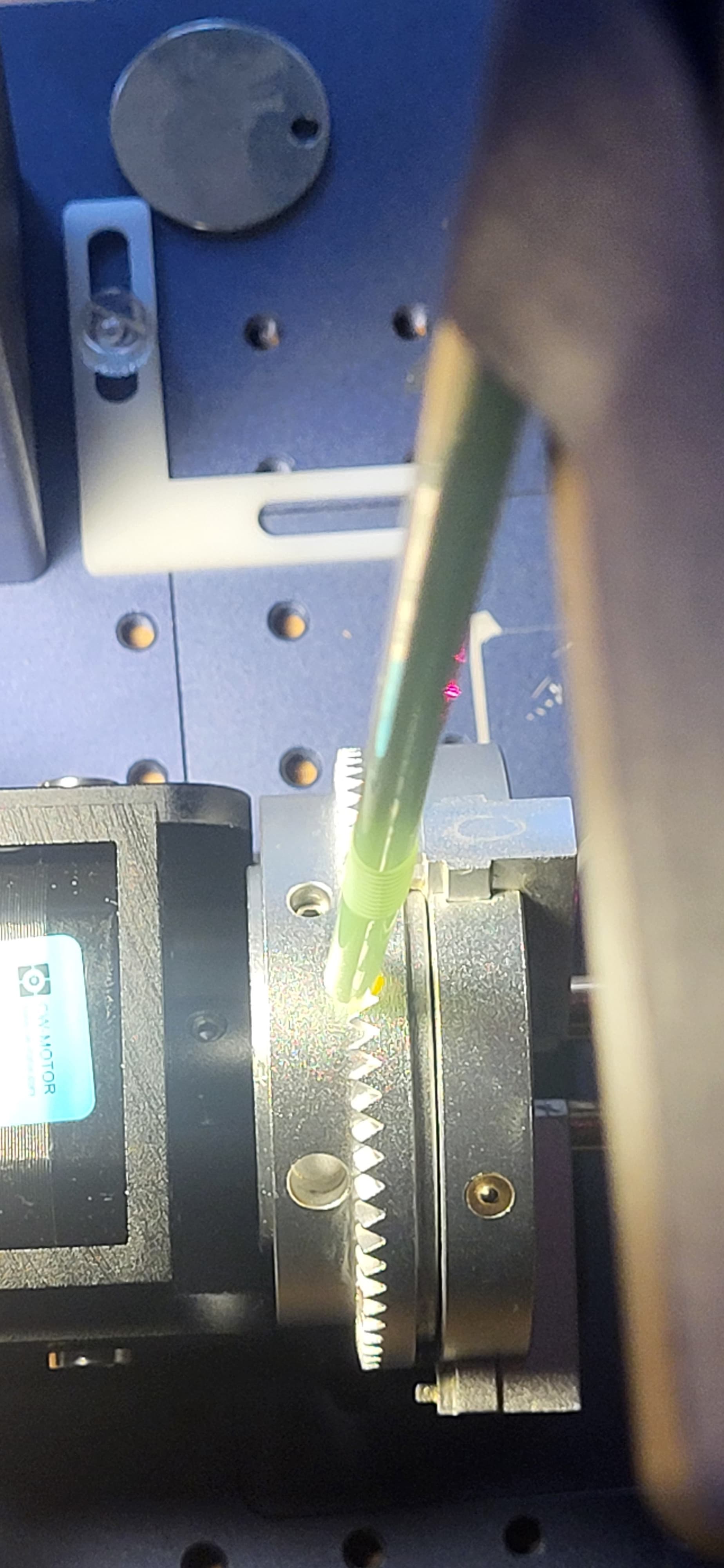
Cannot seem to rid these odd joinings. I am quite new to rotary, but squashed this issue very fast on my co2…am completely stuck on the fiber. I have adjisted LPI and overlap, split size…cannot seem to grasp why it is having these large gaps every stitch.
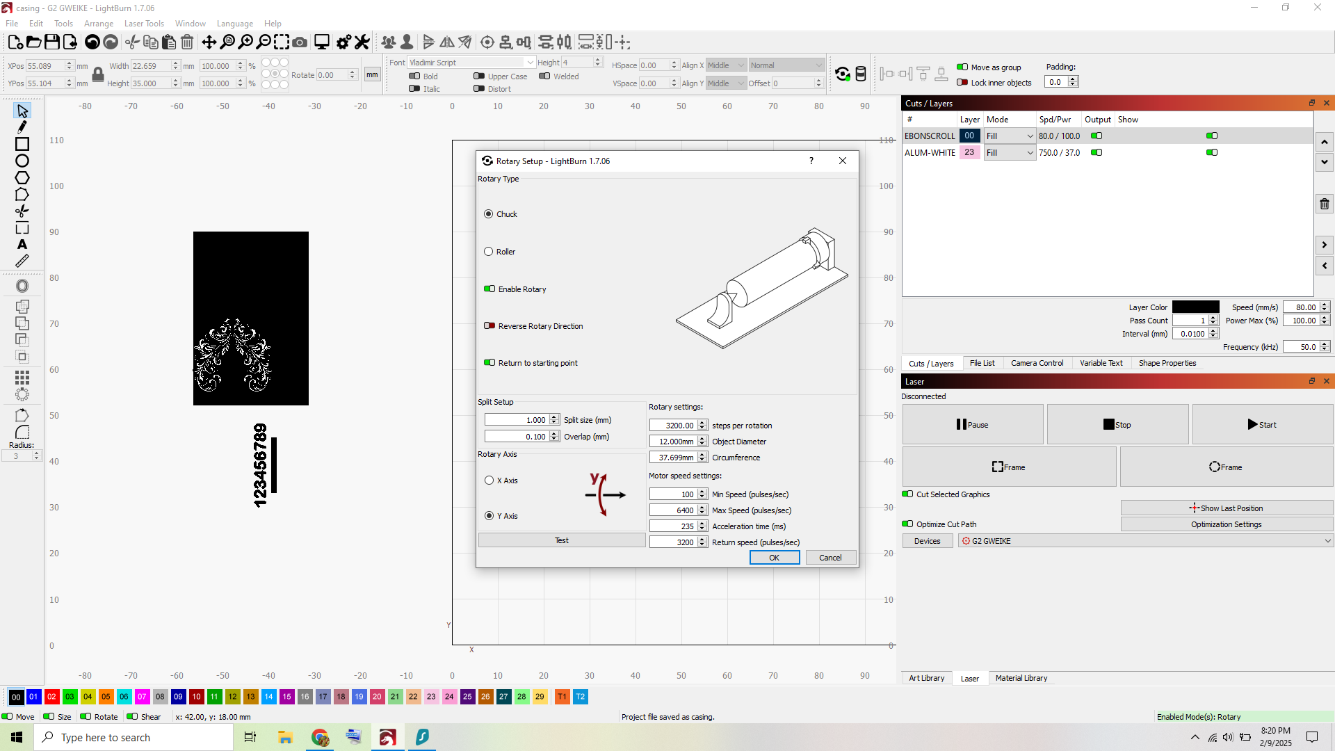
Maybe check the Split size and the steps per rotation…
2 Likes
Sawtooth is usually steps per rotation off or diameter off (or both). Post your settings if you like we will look and ask more questions and sort this out.
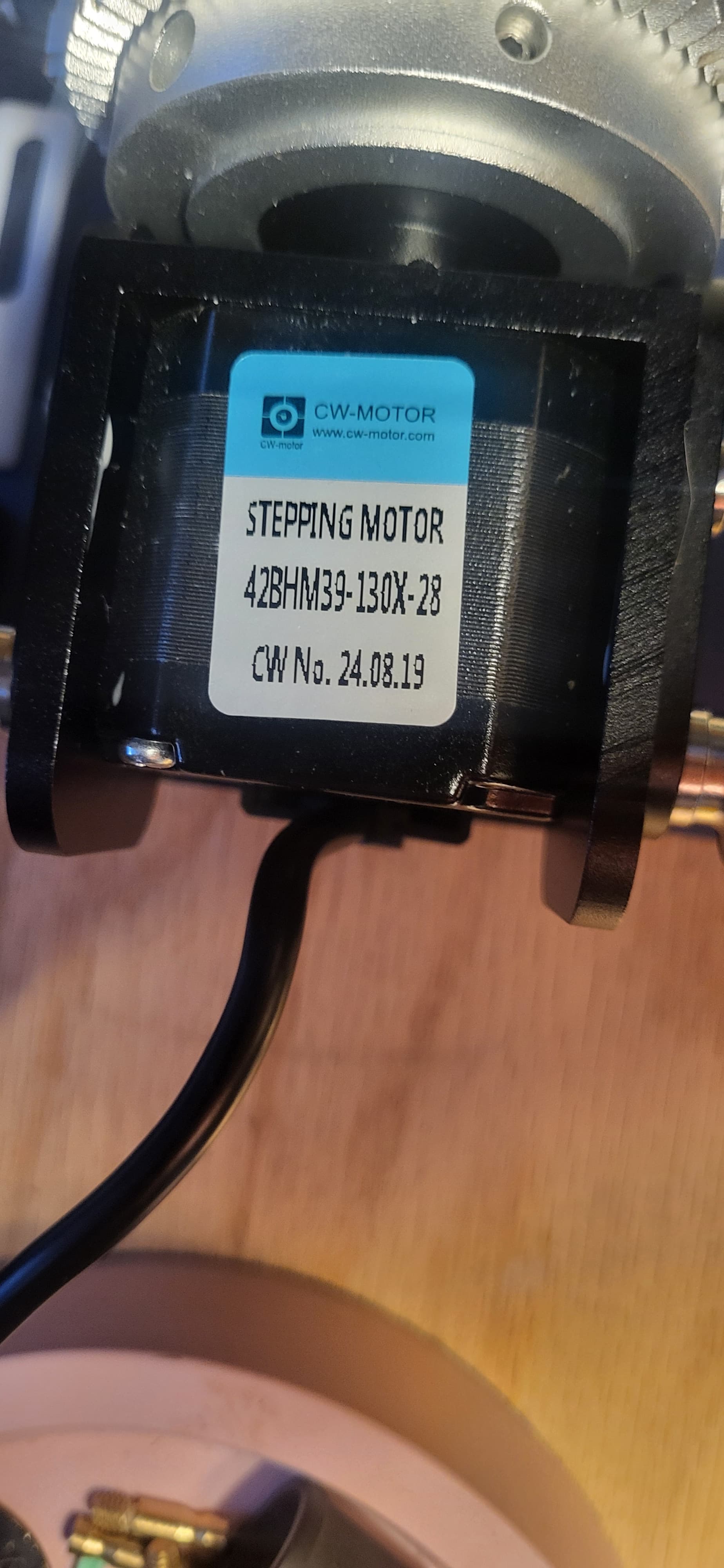
These are straight from the manufacturer.
I have increased overlap/stitch to 2mm and it had no improvement? I have checked some that came out “okay” and I believe it was due to me mis-measuring the diameter of object so it somehow came out fine.
I am in talks (streeeeeetch) with g.weike and they are…not helpful.
I have performed everything to factory settings from their videos.
I asked for specs of stepper motor from their rotary, and they just keep saying they will provide them tomorrow (haha…?)
Will look into that galvo documentation some more. This stuff is a huuuge headache and I wish there was more communication between companies and lightburn to provide their specs. The rotary setup is an issue across every single machine I have used. Xtool diode, Monport Onyx CO2, and now a G.weike and they are all nightmares, though CO2 was easiest to navigate. Sadly the common denominator is all cheap foreign companies with GREAT reputations for customer service.
Anyway, preaching to the choir. Thanks.
when you hit TEST does it rotate exactly 360 degrees? Wouldn’t be the first time someone got incorrect setup from the factory.
Here is a table of different step config’s from one type of microstep driver.
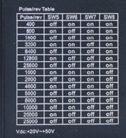
your next tighter steps could be 4000, 5000, 6400…
Set your split to something like 3mm and then engrave a 2.5 mm square, and measure. This test works better with something with a larger diameter, like a yeti 10mm split and 8mm square. But it will tell you if your steps are off and by what percent.
Don’t really have a way to measure that accurately but just putting one of the jaws at zero/top/noon and hitting test shows me it is about 5-10degrees off. Spins one way, then backaround and does not return to spot.
THank you for the table I am working on adjusting the steps/R and back at the testing bench.
I really need to figure this out so have invested heavily in an articulating indicator that I believe will work. n
I foound the correct steps/mm = 4000 (Not 3200 like MFG said) to return exactly to the same position.
I ran the 2mm square test w a 3mm split. It came out fine…
Tried to run the art, failed miserably. Going to try and adjust that now and read into the doc more.
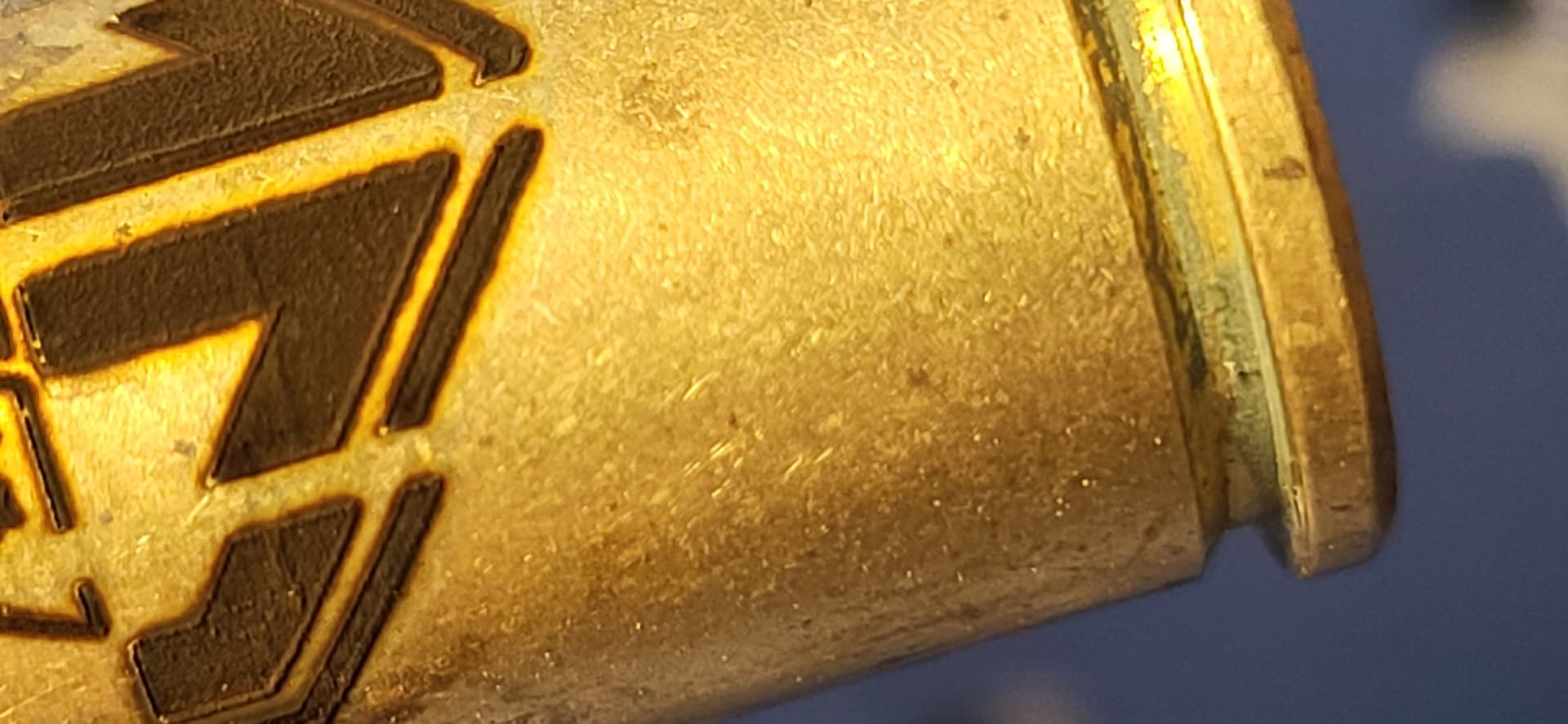
I measured the gap and it is between 0.7 - 0.9mm
1 Like
Ok. Something sounds off, test should rotate chuck 360, and then back 360 to original starting point.
If off, example should be 6400, 3200 should rotate 180 and back to same starting point. If it doesn’t return to starting point regardless of steps something else is wrong/slipping.
I would make your speed and return speed equal, say 3000. 6000 might be too much. Make your acceleration 500. If you get to the point of opening case, make note of the DIP settings on the microstep driver.
2 Likes
Okay this is interesting…although now it returns to the right spot, I noticed that it actually does 1.25 revolutions. Or 360+90 degrees…then goes backwards the exact same…
which means that the correct setting is 3200. What in the world I am walking myself in circles.
I changed it to 3200 steps/mm and NOW it is rotating perfectly. What.
Back to re run all the tests. WOnder if somehow it wasn’t stepping right?
Okay now it is overlapping negatively, or squishing the slices. Looks like this is somehow related to the slice thickness and it wrapping wrong…weird I would think all you need is diameter of object…back to testing overlap or split size I guess
Ok, so no matter what steps, 4000, 3200, etc it should return to starting point exactly.
Did you change the speed settings?
Because you were originally at 3200. So now get rid of the 0.1 overlap, if you measure accurately it should be 0.0.
Next, now that you are getting close, divide the circumference by 3200. Make your split a multiple of that.
The important thing is your rotary can only stop on multiples of Circumference/Steps. Including your overlap setting.
1 Like
How large a split (vs. circumference) do you all generally choose when using a rotary on a galvo? When I’m directly engraving (black marking) on stainless steel, the edge effects between splits are quite noticeable if I’m using more than a trivially small split size (something like a couple times the line interval). If the individual parts of the engraving are small enough, a larger split size with “Run whole shapes, if possible” set would avoid the edge effects, of course.
Does LightBurn correct for the geometry of a cone (beam from the galvo head) intersecting a cylinder? I figured that was why my diagonal line segments didn’t line up perfectly at split edges. (Of course, I’m generally engraving on things that aren’t simple cylinders, so even if LightBurn did geometric corrections, it likely wouldn’t help me.)
I’d love to use a split size an order or magnitude or two higher on my Contigo travel mugs, but so far, it’s a trivially small split size (with the much longer runtime) or split edge artifacts.
There is a setup procedure… this is for a rotary on a co2, but it’s the same game.
Much more complicated is to use your motor (twice the size of mine) step angle you want based on the motor.
It’s more simple to look at the motor driver and read off the steps/rotation than doing what you’re doing with a crap shoot. Just do it the right way and it should work.
These are digital and it’s not going to be a step shy on one or the other… In other words, they work correctly digitally or something is broken, not necessarily improperly configured.
Mine is set to 12800 steps/rotation with the chuck.
![]()
Get the circumference divided by steps dialed in, make your split a multiple of that. Make your line interval a divisor of split. . 0.0 overlap. On a mug you should be able to run around 4-5mm. Using this method have gone between 0.9mm and 1mm on a ring with no artifacts.
Finally got gweike to weigh in on the problem. Figured I would drop their responses here to help.
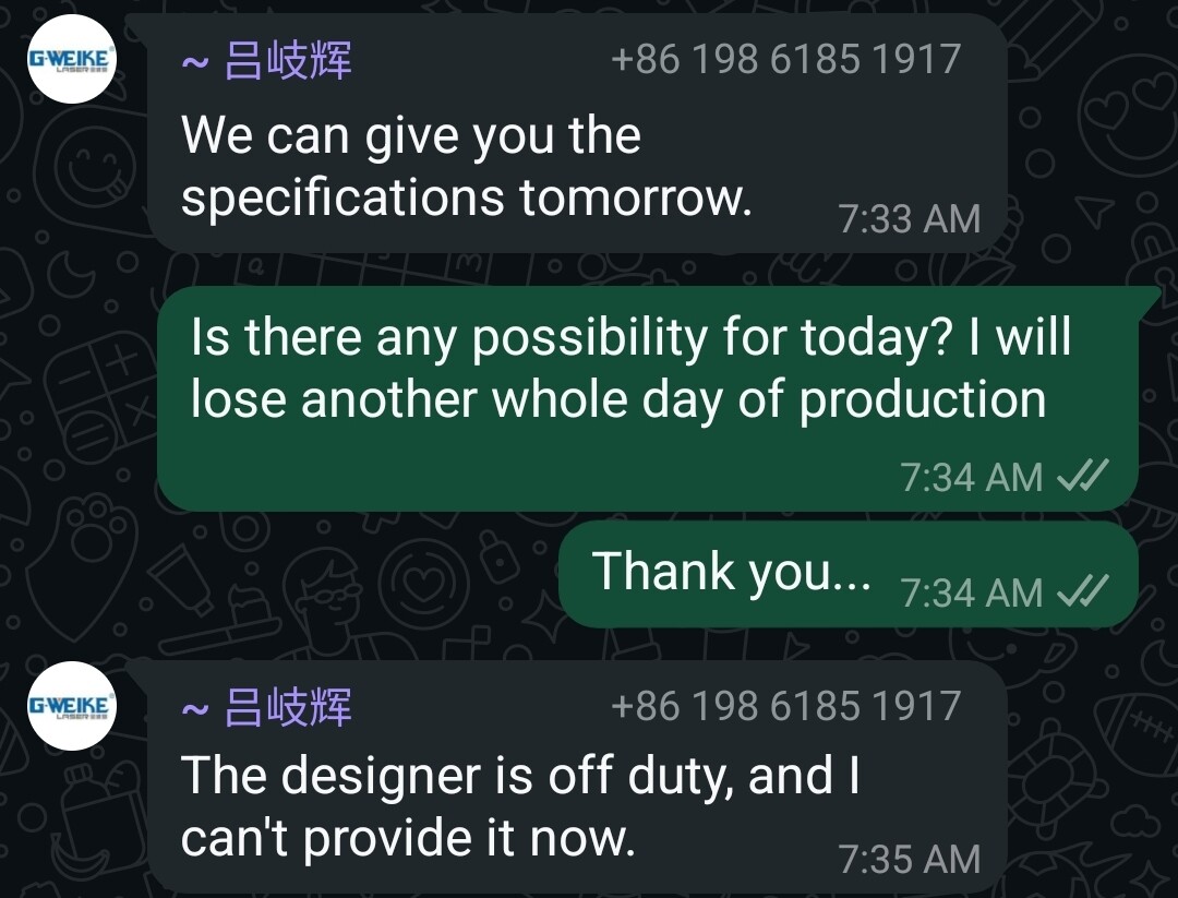
Week 2

Week 1
Tomorrow tomorrow we may help you tomorrow its only a day awaaaaaaay
Kind of what I would figure… at least they answered you.
Did you check your steps/rotation from the link?
![]()
1 Like
This is true.
I have played around with the steps/mm but I am still unable to make any progress. It seems that I may have to tear into my machine to check the driver plate as suggested. I retrieved some info from the motor manufacturer that confirmed this as well. I have had some commercial work to do w my co2 so haven’t had time to continue tinkering with the fiber/rotary…soon. I am anxious to solve this for sure, and appreciate all the assistance.
Keep us posted.
OKay I am back at it.
A hollow cylinder is measured in the middle at 13.0mm. It has a circumference of 40.841mm. Divided by 3200 = 0.01276 A multiple of that for split size is 2.552mm. I have a 0.0 overlap.
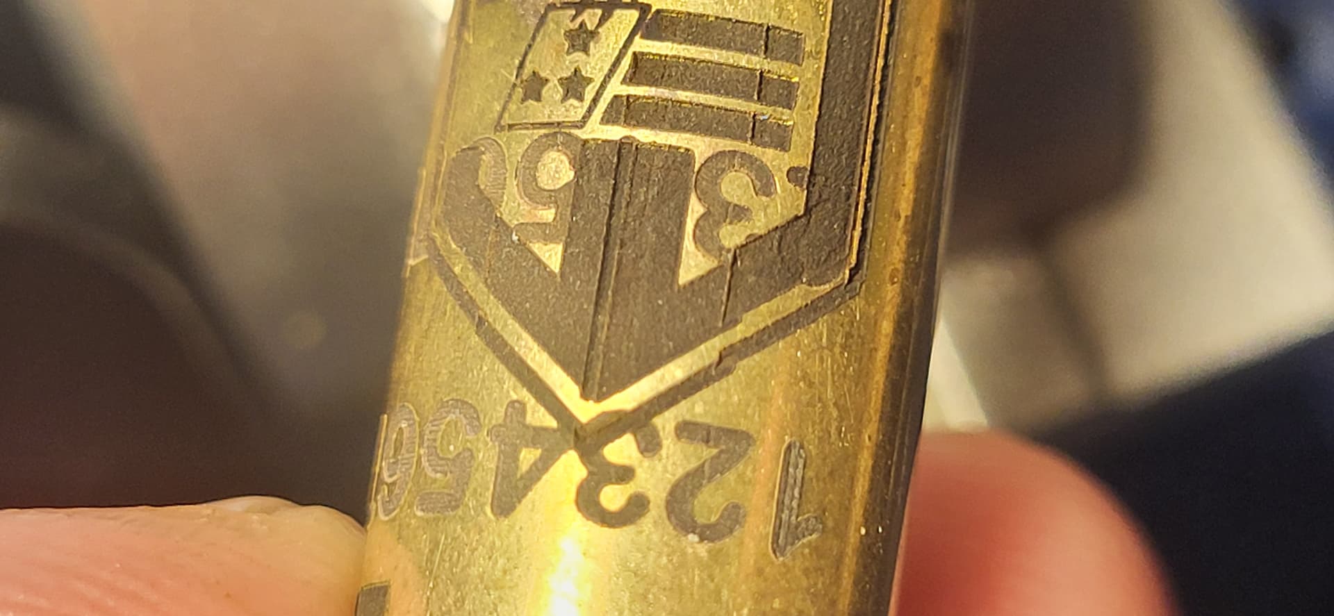
With those settings ran near the end of the cylinder with a true diameter of 13.5mm, steps appeared every 2.5mm (the split). The same settings, ran near the front of the cylinder with a true diameter of 12.5mm, steps appeared in the following manner: the first 2 split lines were overburned, then the split lines showed on the 3rd and 4th split line, then the remaining 4 splits were overburned.
I realize I am dealing with a slight taper here 12.5mm-13.5mm diameters, or a 1 mm taper.
I tried checking out the taper tool but it appears to adjust the art if it appears skewed on the rotary, and doesn’t seem like it would apply here. I do see a cylinder correction tool also…
Found a perfect 13.5mm diameter cylinder w a circumference of 42.412mm
That, divided by 3200 = 0.01325. Ran w 2.650mm split size, 0.0mm overlap.
Now it is overburning. I am not quite wrapping my brain around this, as I keep having to adjust up or down in relation to true dimensions. I have to be missing something, or is it really this big of a pain to do every burn. I do not see how it is feasible to have repeat setup for different objects if each item requires so much individual tuning.
Whether I split it into .5mm or 2.650mm or 3mm, it always has a line at the split, no matter what. However many times it splits it, there are that many lines. I have adjusted diameter up and down, overlap up and down, and I cannot for the life of me get the stitch mark to die.