Hi there,
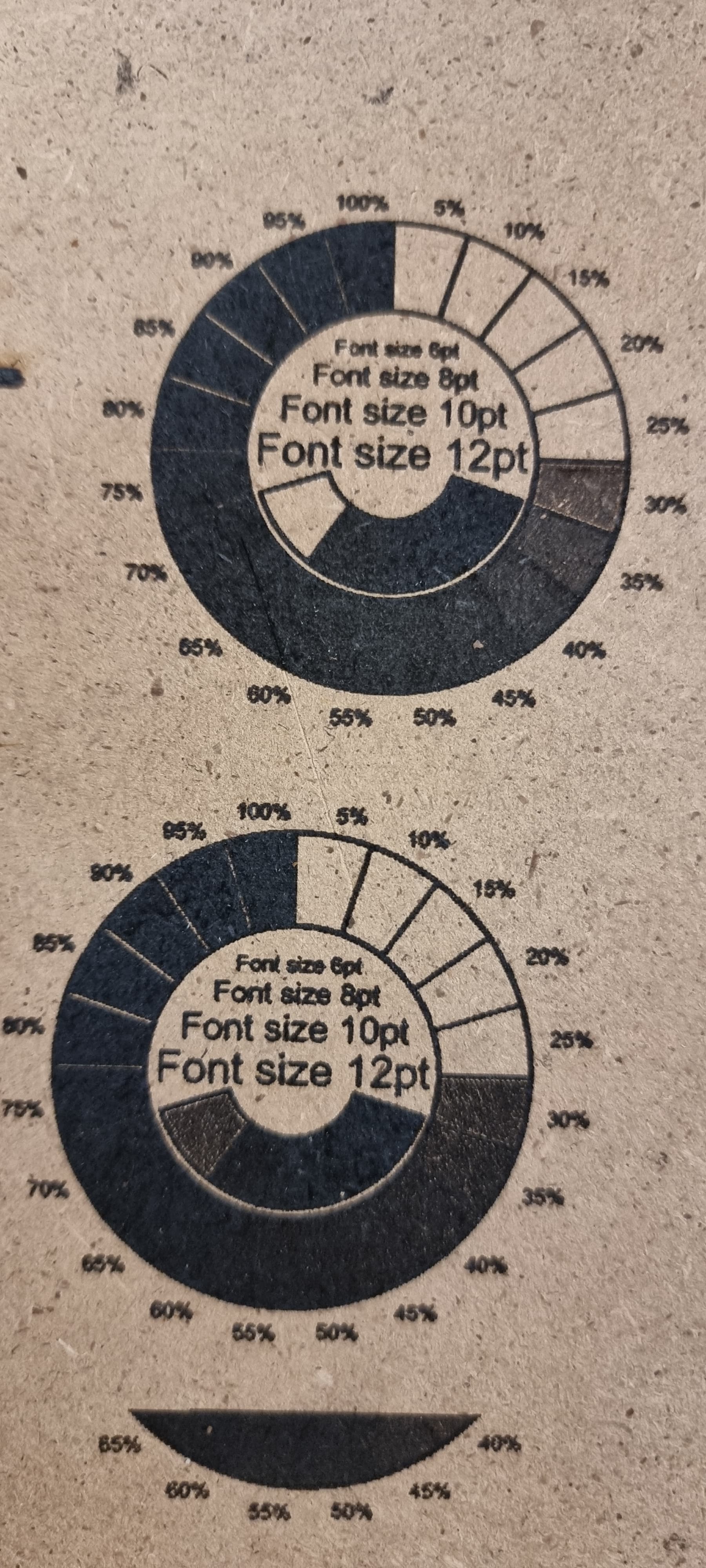
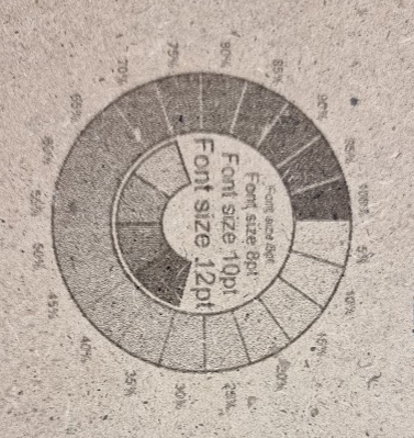
Few days ago I bought a LM2 Pro with the LU1-4, fired it up and did a few test runs. Couldn’t cut thru any plywood at all (not even the balsa pieces which Ortur gives away). Tested engraving on different materials and it seemed good altough. Some touches needed but I was somehow satisfied. Yesterday I tried to engrace a test pattern (the circle with gradient) onto a MDF. It worked with neither settings - blurred or burnt or else what. Until I found someone on one of the forums who pointed similar problems and posted a picture of his laser dot, which was more a line. And also was mine. I then tried to raise the Z axis and got to a tiny dot. Tried engraving and boom - all those settings I have learned got past. I did the focusing on all materials - before raising the Z, but with that cylinder from Ortur I got the line beam instead of a dot. The cylinder is 29mm high, to get a beam point I have to raise my head up to about 49mm or even a little bit more. Is that normal or am I misunderstanding something. But what happens also is I’m getting a tiny circle around my veam dot when raising the head. Now with the focus height about 49mm I can engrave clear lines but with much much less power and much greater speeds (for plywood engraving I use 3000mm/s and about 20% power). But the problem I have bow is that everything I put out is either black or not engraved - when I lower the power from 20% to about 15% I can’t see any changes, but at about 13% it’s just very very light burn and then at 12% it’s nothing more.
I’m obviusly doing something wrong and can’t get it right. I tried LaserGRBL and Lightburn, no difference, same behaviour. Also tried the power pattern out of Lightburn and engraved some patterns I found on the web…
I would be very pleased if someone could point me in the right direction. I’m thinking that maybe there is some other lens mounted and that’s why the focal lenght isn’t right. I don’t know. Thank you all in advanced.
Your specific variation might be a little different but here’s what I found on one site about focus height:
Factory focal length (adjustable): 20W: 55mm from light outlet (from bottom of radiator)
Your cylinder might be designed to go under the lens, not the radiator. I think they may have changed this in a version update. Either way the height itself isn’t a problem but you should probably run a ramp test either way to make sure you know where the ideal focus height is.
Your actual engraving does look like it’s a problem, however. Seems like you’re not getting much power modulation. There could be a few different things going on at different levels.
Can you provide the following to help narrow it down?
Upload the .lbrn file that you used for the test burn. There might be something going on in the design.
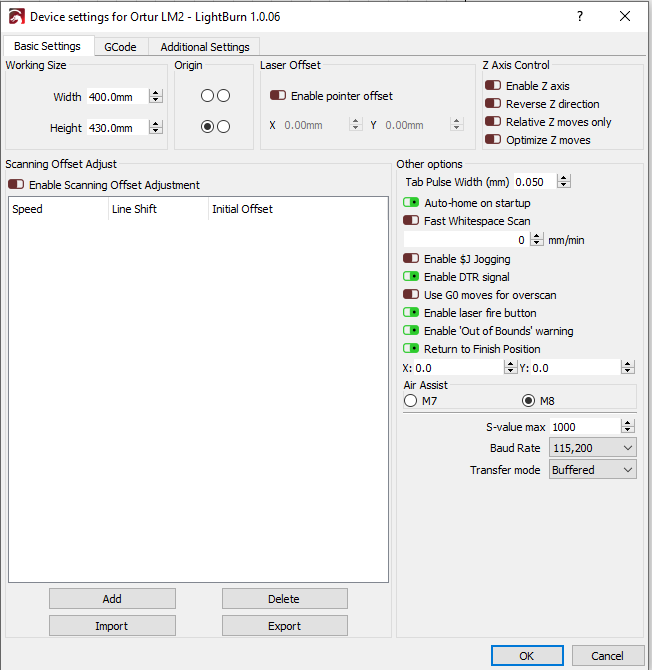
Attach a screenshot of Edit->Device Settings.
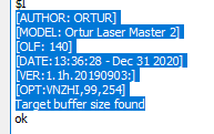
Type $I into the Console window and copy the output text here.
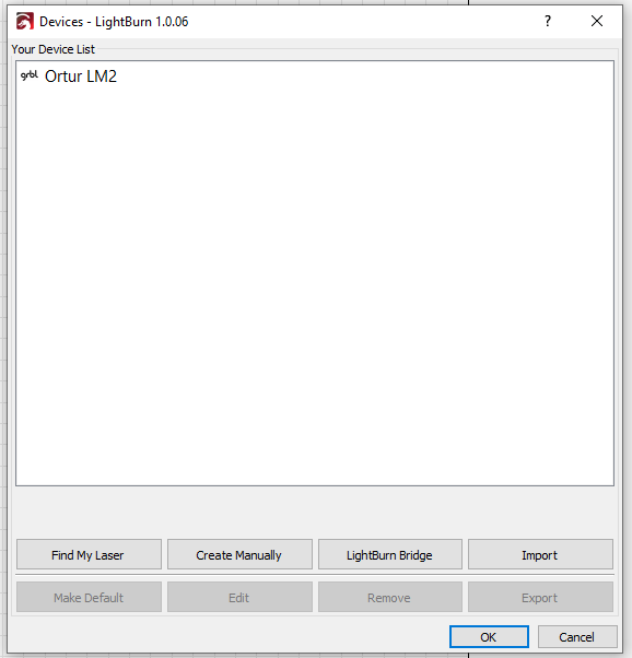
Click the Devices button in the Laser window and take a screenshot.
Hi,
I checked that focal lenght. If I put the clinder underneath the light outlet I get a focal lenght of about 45mm, which still produces a dot not a line. That could be right. But it’s far away from the 55mm you are mentioning. Now to the files.
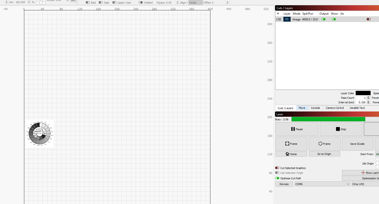
1. powerScale Basic Power-1-100 Speed-100-1000_backup.lbrn2 (45.9 KB)
I corrected all the speeds (for layer Labels to 2000 and other layers from 500-1400). Everything engraved was purely black from
2. Here are my device settings
Hm, now I tried some more images and text out of Lightburn. It seems pretty ok. Don’t know what was happening before. I’ll have to tune my power and speed settings to get the desired results, but I think I’m on the right way now. And would love to purchase the Lightburn license to get it working right and good. But will also be very happy if you check my settings I posted and give me some comments. Thank you very much.
BR Dean
Other than the speed settings that you pointed out I don’t see anything particularly wrong in the .lbrn file. Normally the scales go from 10-100% so that you can see the effect of 100%. As long as you can see a gradual increase in darkness between bands you’re good. You’ll jsut need to make sure the speed settings are correct. Just the fastest speed to the highest where something is still burned at the lowest power setting and go slower from there.
I’m not an expert with this method but a few things that stick out to me.
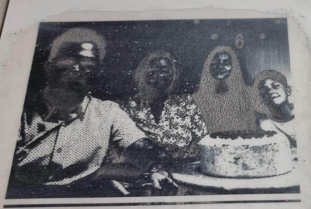
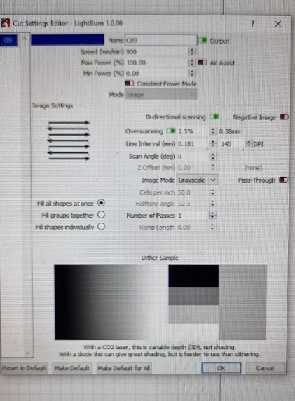
I think this method typically uses dithering rather than grayscale. I don’t believe this technique allows for variable shading of the marking. Try changing to one of the dithered image modes. This is likely the primary cause of the overexposed look.
I suspect your power level will be too high. You can experiment with this to get optimal results.
You’ll want to experiment with Line Interval as well. You want the line interval that results in the darkest output.
Hm, thanks.
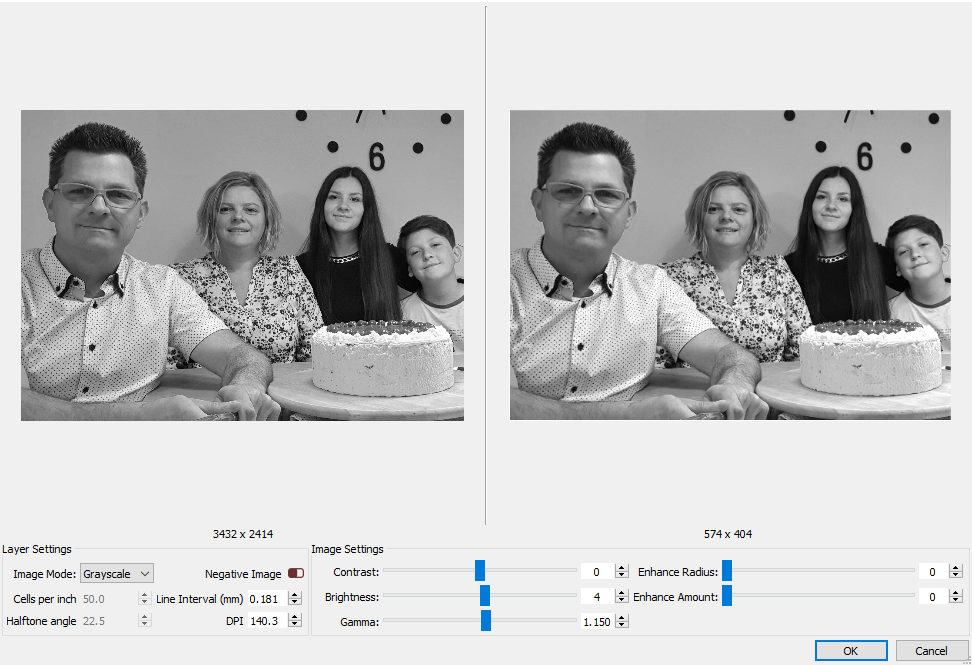
I got that settings from a YT video, from a guy with the same laser (LM2 20W) and he got great results. In his video there are at 10:47 all the settings I used, but had no lick getting a nice image out. Strange…
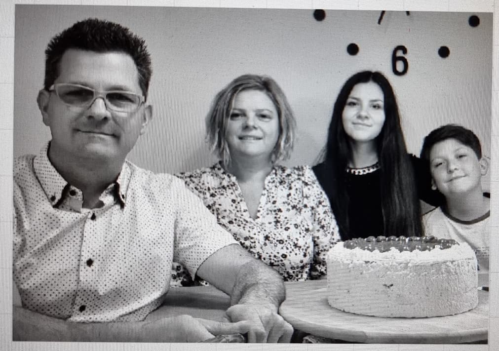
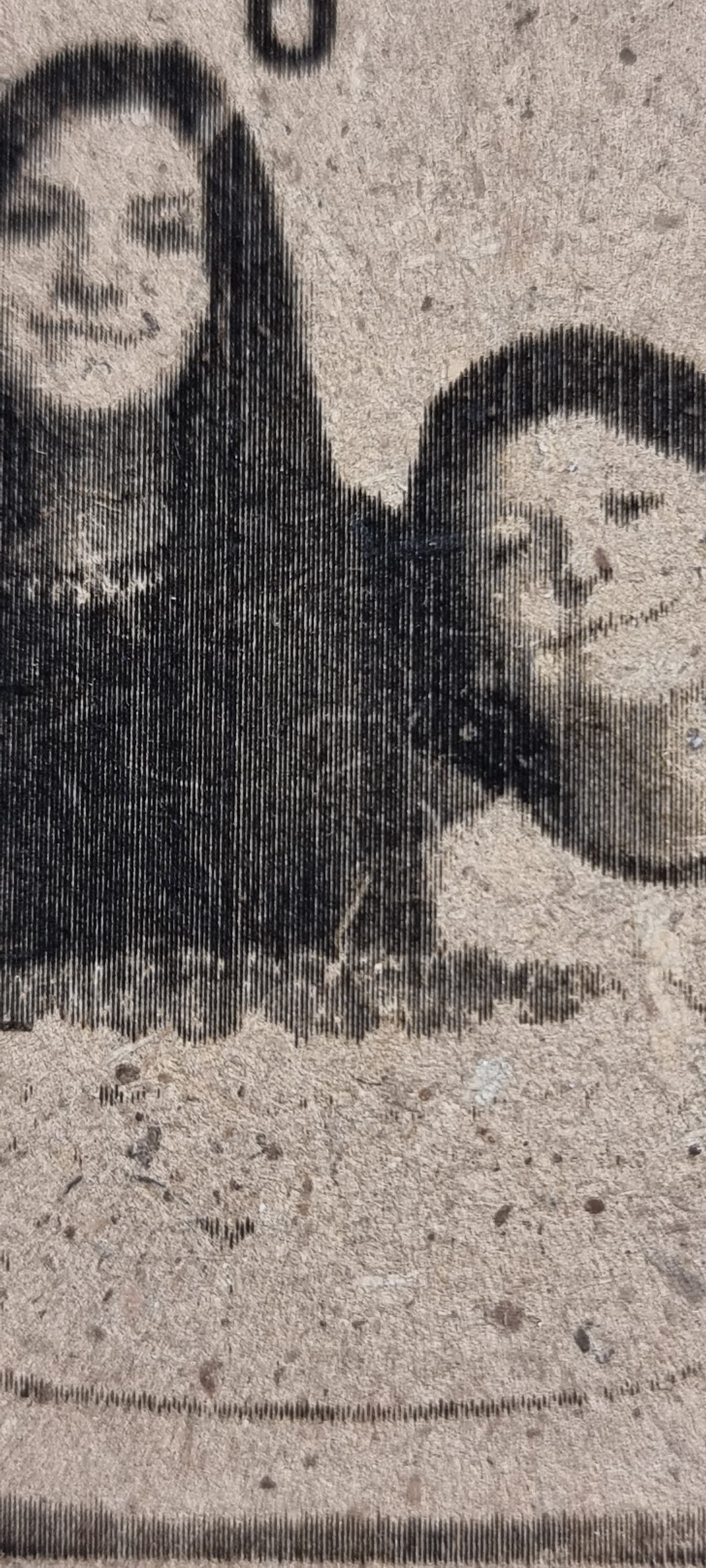
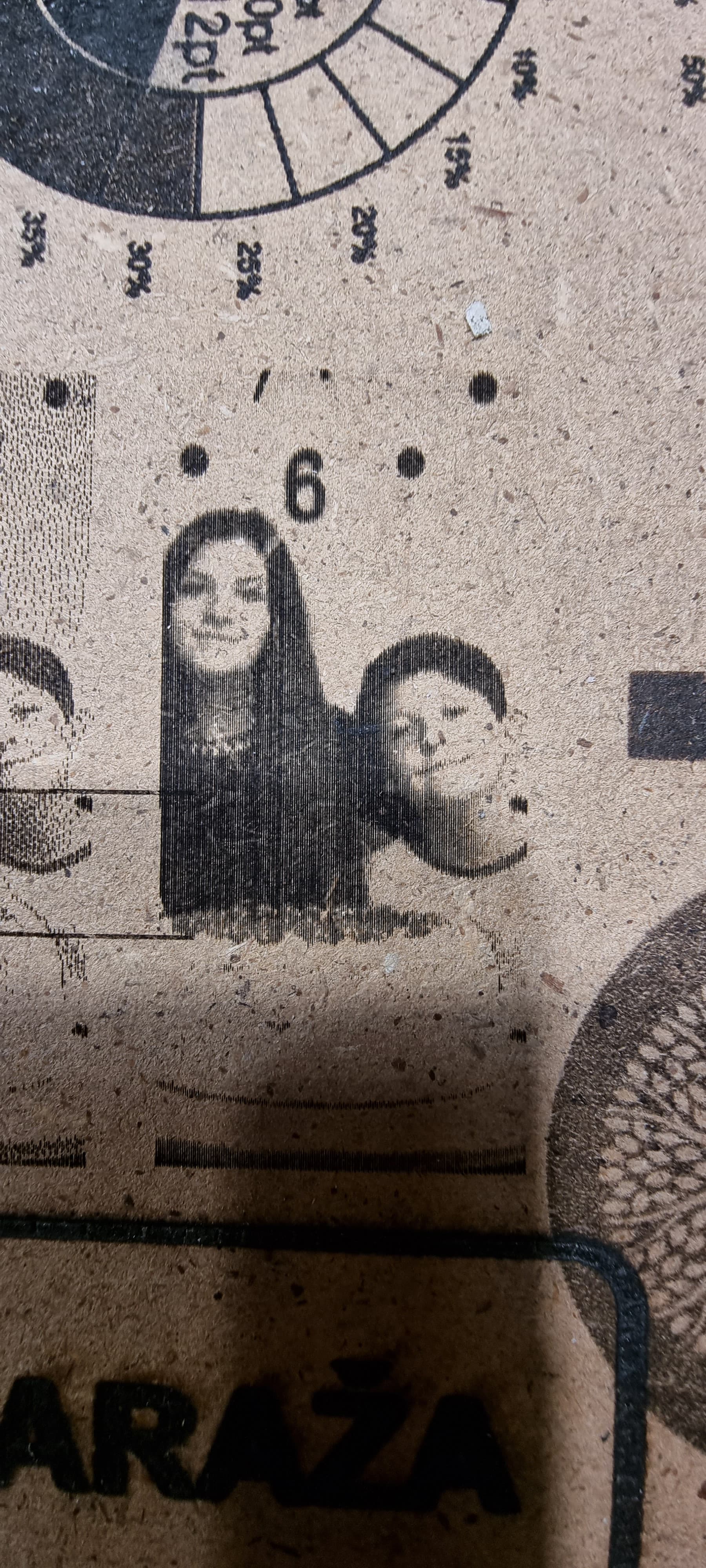
I obviusly have a problem with the line interval you mentioned. Have gone thru some videos and engraved a portion of my picture to a mdf for test. On a closer look there are real empty lines visible (engraving angle set to 90)…have to learn a lot lot more.
So looks like grayscale is valid although I’m curious how that would work based on the theory of how this technique works. But note that he’s not using the the same laser as you. Looks like he’s using an emblaser 2. So your settings would be different. Even with the same lasers tweaks are generally needed to get best results.
If you want to continue experimenting with grayscale in your case either increase speed or reduce power. Personally I’d start with reducing power since I don’t want to run at 100% in general.
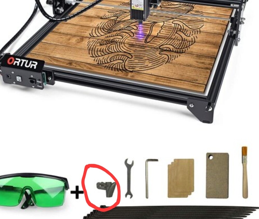
Me again. Still jumpin’ around with the settings. I figured out that I have a LM2 not the Pro version, with the LU1-4 which has some strange focusing ring on the lower end of the lens. Figuring out how to get the max out of that small beast - but can’t really cut thru any ply thicker than 1,5mm. Ordered now a air assist nozzle, hope it helps me out. If not, gotta get some higher wattage laser. Unable to cut about 3mm ply isn’t gonna work for me. Until then - I am wondering what’s that small plastic part included in the box. Gone thru many manuals, videos, seen it everywhere, but nobody mentioned what this is for. Maybe here someone knows?
That part is a tool designed to help you thread your cabling through the twisted cable housing.
Can you confirm whether or not you have a fixed focus laser? I believe that module at one point came with a variable focus lens and later moved to a fixed focus lens. If you have a variable focus lens you need to be very diligent about getting proper focus. Fixed focus models make this a little easier. Those models come with an aluminum cylinder to help set ideal focal distance.
Any cutting operation in general is a non-trivial exercise and requires a good setup to do with success.
Hi,
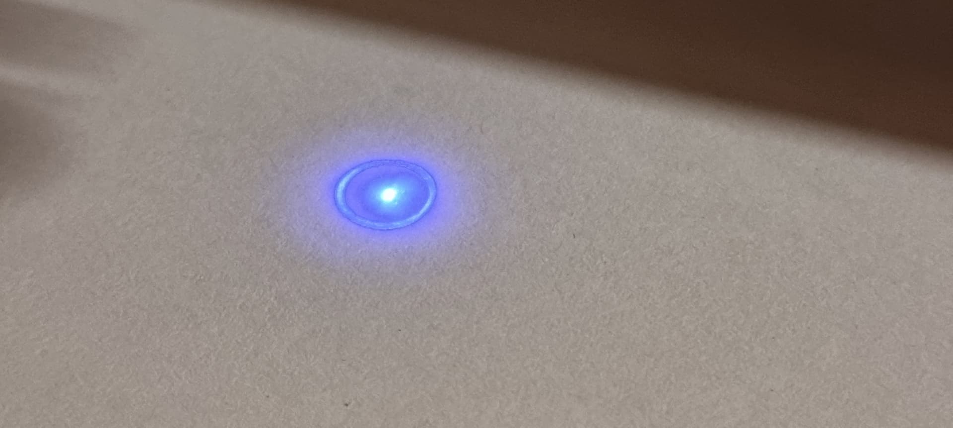
I am still struggling with focusing that little beaat. I think I found that sweet spot, but have now a circle around my beam point. Is that normal?
That doesn’t look right but can’t tell if it’s just the photo.
Can you confirm that you have an adjustable focus lens? If so, try this:
Start by getting something dark as a base to focus on. I’ve found that black cardstock works well. Black will reflect less light and allow you to see the beam better.
First set the distance of the bottom of the heatsink portion of the laser module to the work material to 55 mm.
Fully tighten the lens. No need to overtighten.
Push fire in LightBurn and set power to the minimum where you can clearly see the beam on the dark material. Lower power reduces blooming and allows for better focus.
Very slowly loosen the lens in increments until the beam draws into the smallest point possible. If you overshoot then retighten and check again. The focus dot should be the most intense and thinnest line possible.
If you find that the lens wiggles a lot while doing this it can help if you apply some teflon tape around the threads of the lens housing. I liked it where there was actually some resistance when turning as it made precise movements easier. Make sure you have no excess coming off that could potentially block the laser beam. Be careful as you remove the lens as there’s probably a spring inside that you don’t want to lose.
You could verify focus by running a focus ramp test. It should be in best focus at 55 mm.
Once completed you could choose to use this as a fixed focus by always setting distance to 55 mm from material. Just make sure you don’t bump the focus ring.
Hi berainlb,
Thanks for your efforts. Been away for a few days. I can’t really tell what type of lens I have. Is it fixed or variable focus lens. I think it is a fixed one - hence of the manuals and the alu cylinder which I got in the box? I can turn that lens but nothing happens with the beam, I suppose it isn’t meant for focusing purposes - it just rotates around. Hence I can move that “cylinder” up and down (not really smooth, but it goes), but don’s see any meaning in that if I move the whole laser head up or down on the z axis for focusing. Little confused…
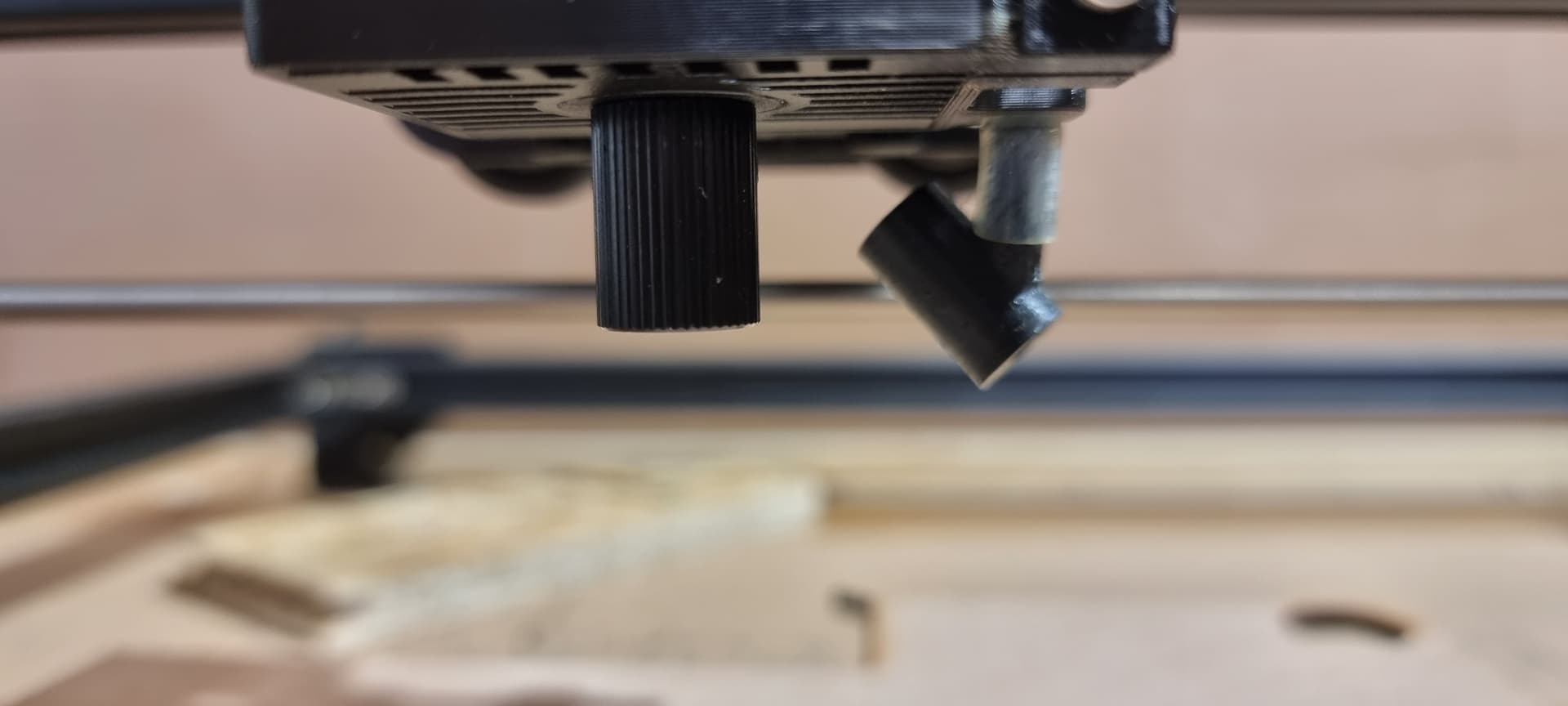
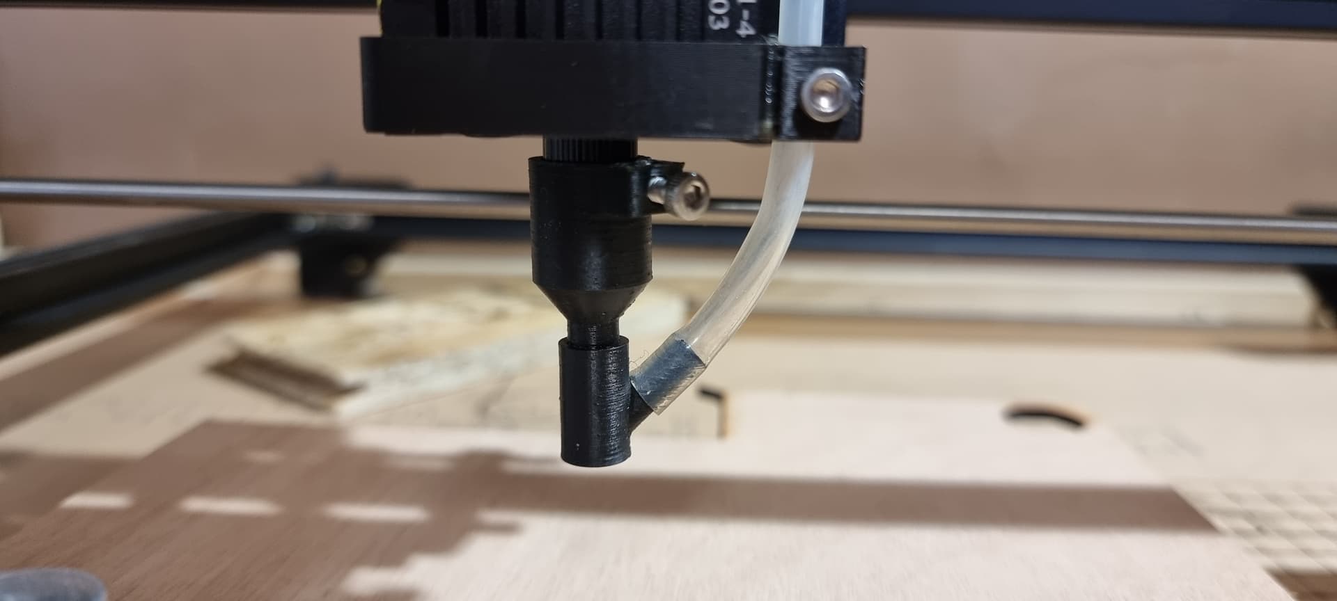
But it seems there is something wrong - either with me or the lens. I changed some materials, tried many settings. One day I can cut my 3mm ply in 4 passes with 500mm/min and 85% power, the next day I have trouble engraving on this same material with 1200mm/min and 50% power. I’m using air assist for cutting, as at the engraving the air assist doesn’t seem to make any difference. And even after doing some cuts, I have to disassemble the nozzle, take the laserhead of and clean the lens, because they get all clogged and I even can’t engrave anything with it. Might be a problem with the air assist design (closed nozzle instead of the one which stands aside of the laser beam…). Attached some pictures for better understanding. One day I get really good results, the other day with same material and settings nothings goes well. Don’t know how to proceed to get it working right.
If it came with a cylinder for focusing that means it’s fixed focus. I’m curious now if you’ve thrown off focus by unscrewing it. I don’t know how the lens is mounted in the fixed focus module.
I suggest you run a series of ramp tests to recalibrate or confirm your focus.
setup an angled piece of material where it goes from low to high depth. Align it along X or Y axis
make a single line design in LightBurn with an appropriate setting for a simple line engraving
set the height of the laser module to about the mid-point of the ramp
run your job
review burn for thinnest most intense line
adjust focus until the most intense line correlates to the height of the cylinder
you may need to repeat the test multiple times if your focus is very off
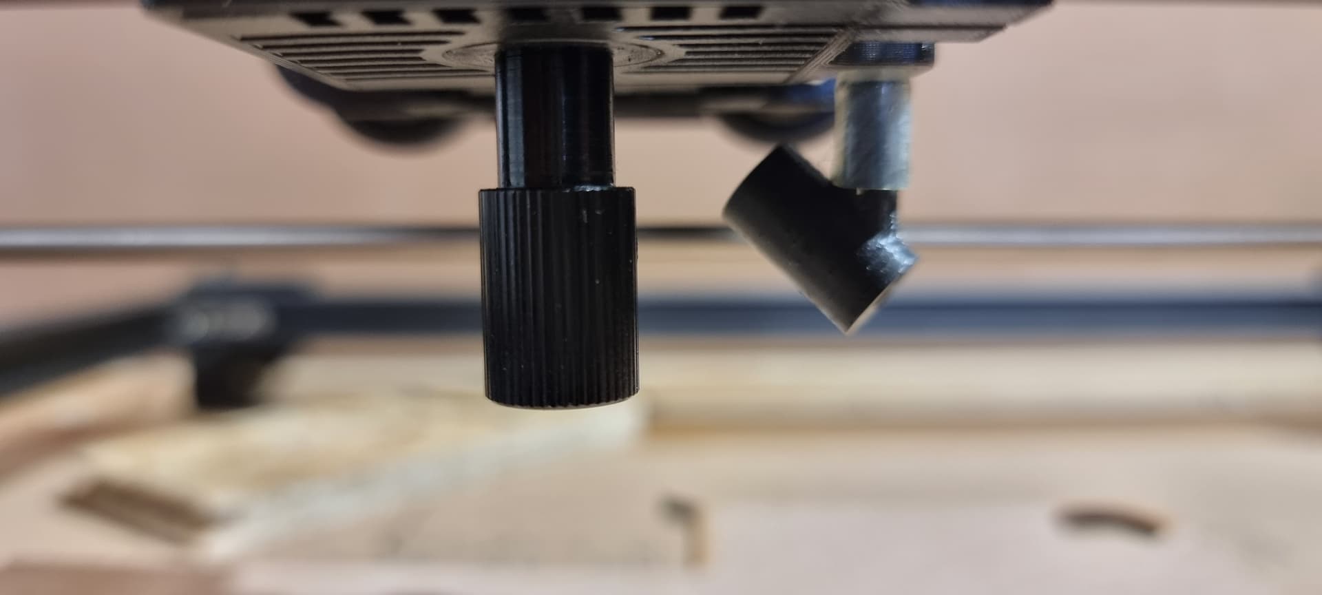
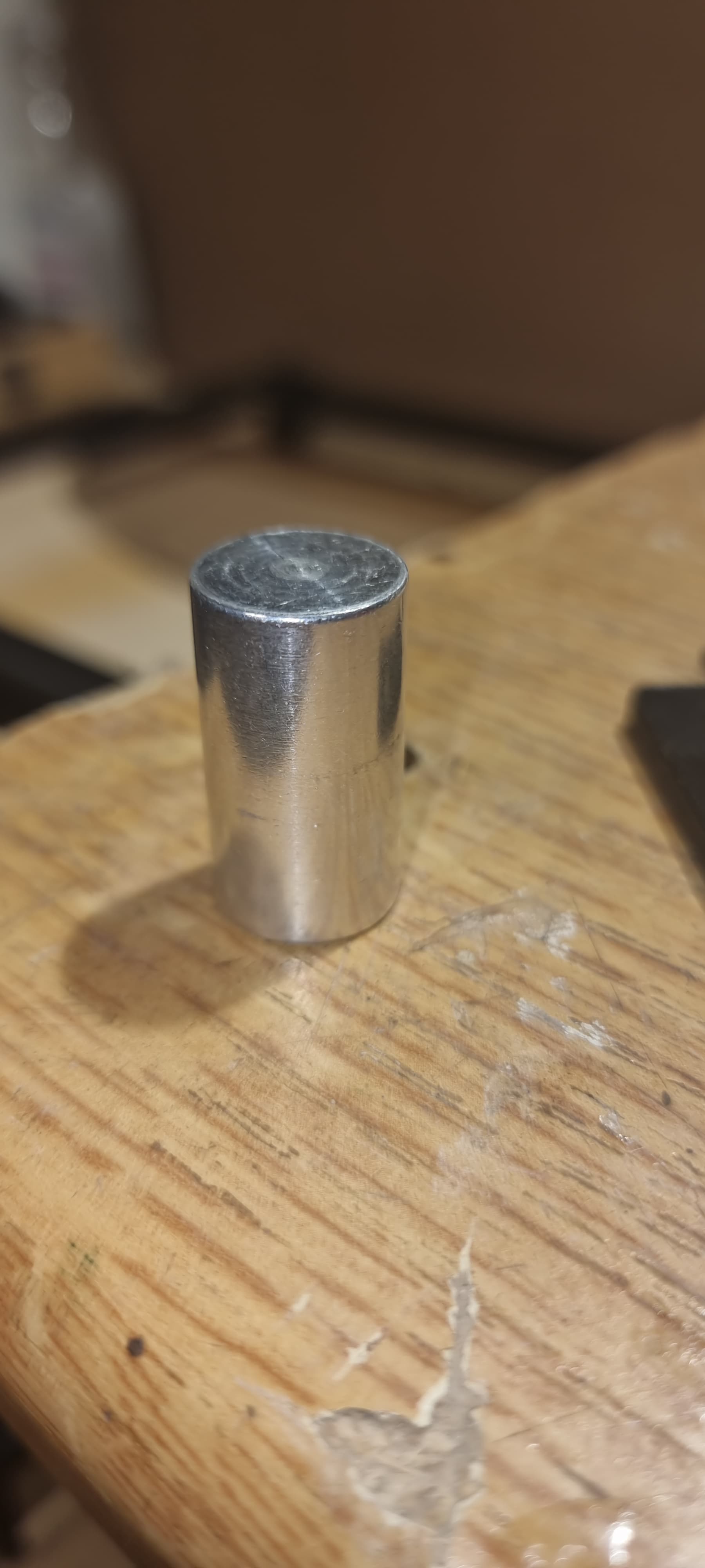
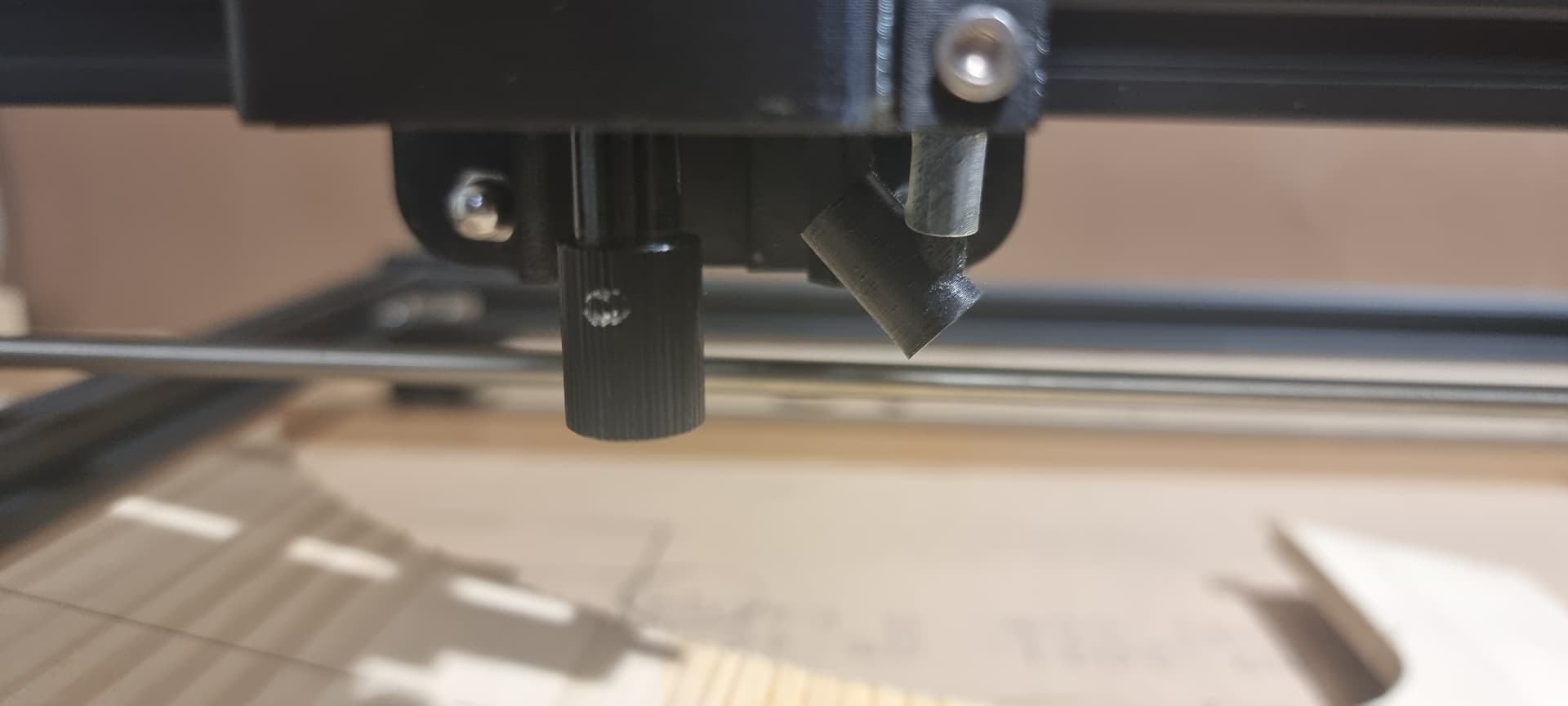
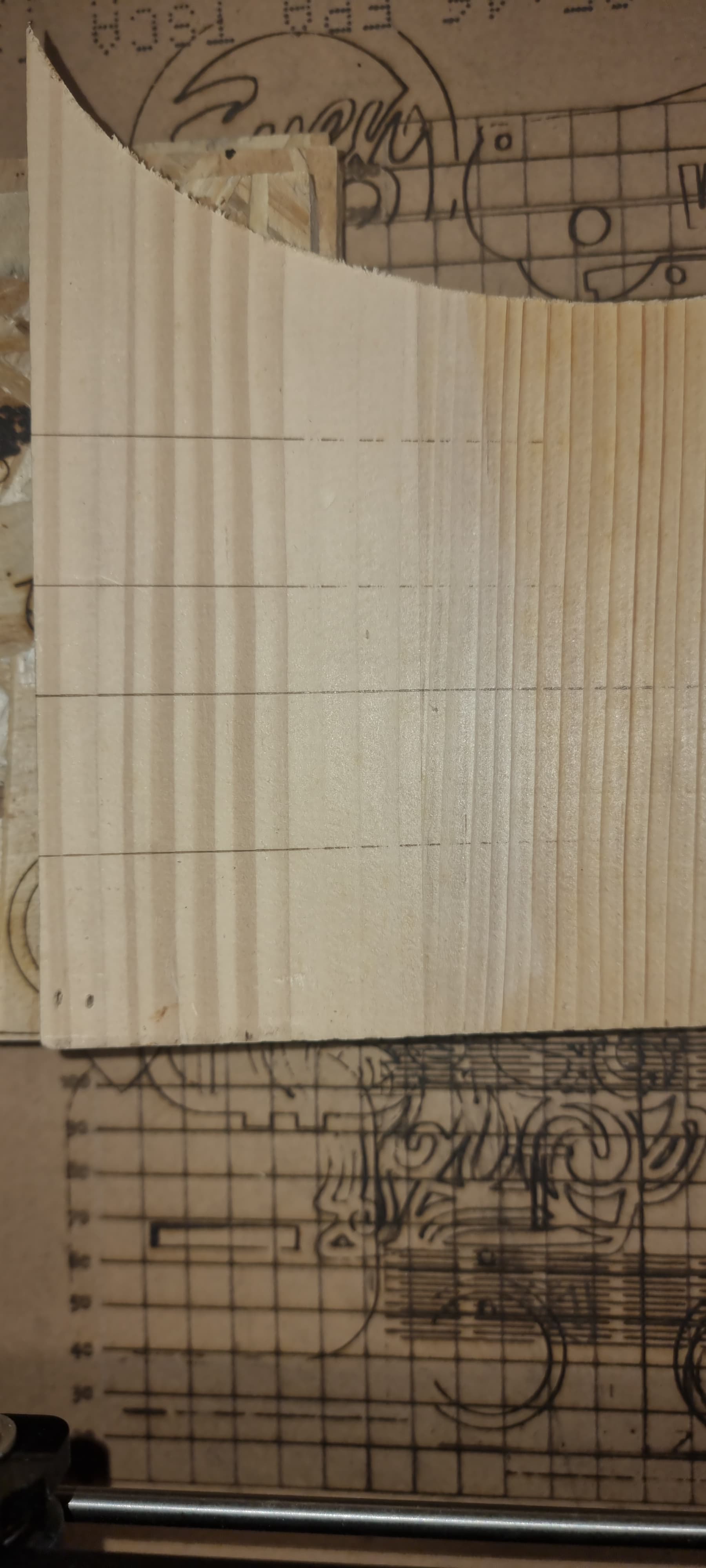
Ok have done that ramp test now. First, to clear these cylinders. The focusing cylinder is the alu one (picture 1), the other black one (picture 2) is fixed under the laser head (maybe thats the lens itself?).
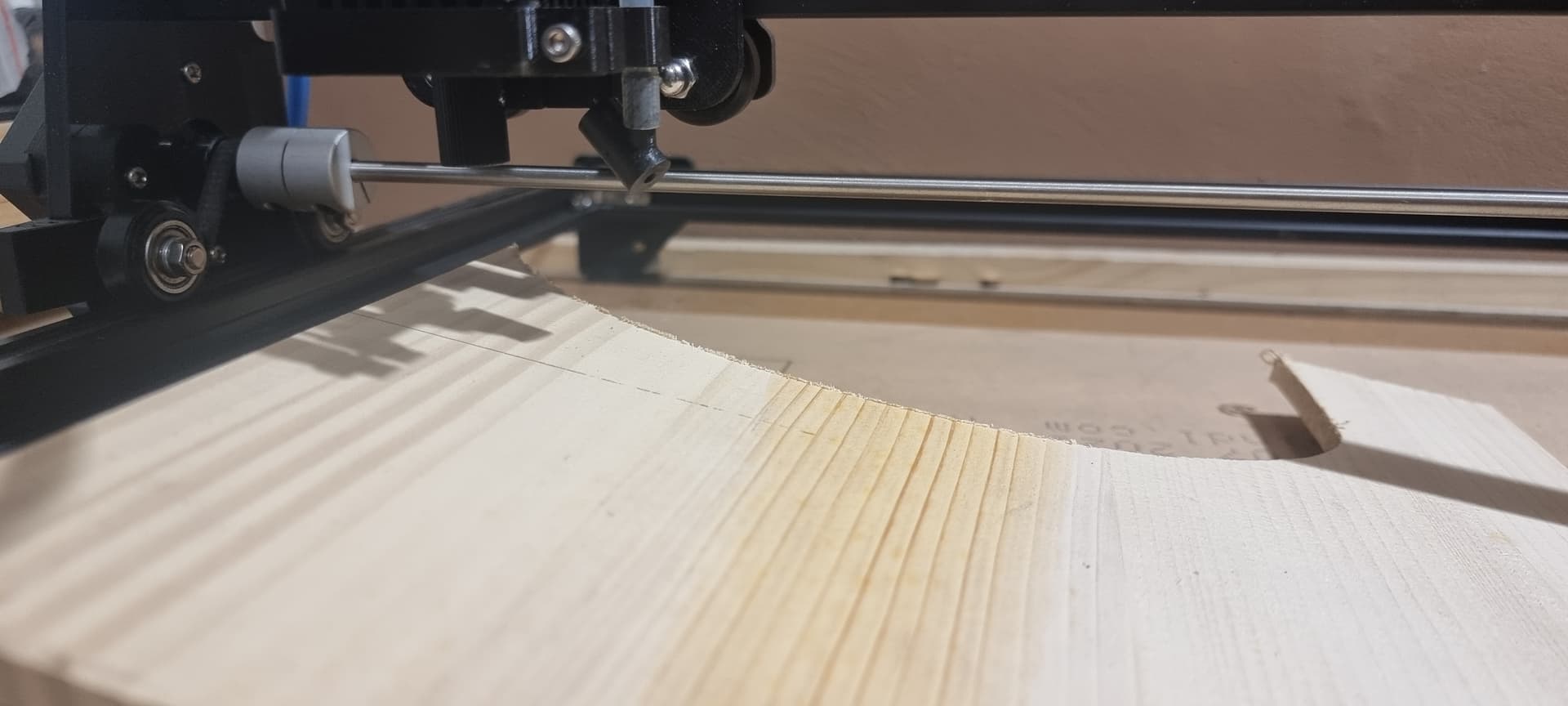
I made a ramp, focused the laser on the very high end of the ramp with the alu cylinder and the black one all in/all up (picture 3) and ran a test (first line).
Picture 3 - first line, focused on highest part of ramo, black cylinder all the way up
This is the lens mount. I can’t recall where in the mount the lens is situated. I’m fairly certain the mount is meant to be fully seated against the aluminum module block so work it back in to start.
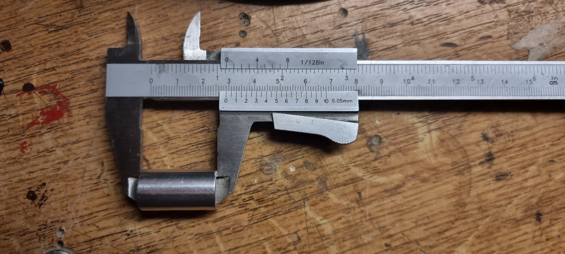
Can you measure the height of the focusing cylinder? If it’s 55 mm it’s intended to be focused from the bottom of the aluminum module. If it’s 30 mm it’s intended to be focused from the bottom of the lens mount.
What is the height differential of the ramp from lowest to highest point? Try to get at least 50 mm differential or more if you can. As much as is reasonably possible to exaggerate any focus differences.
Makes sense that this one would perform the best along both left and right sides but you’re not getting much variance to make a decision.