This is more of an ask for afeature than anything.
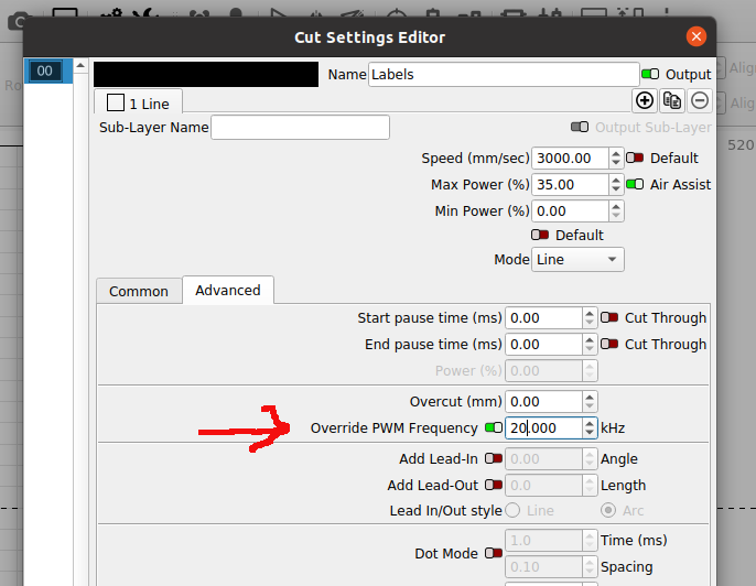
Adjustble pwm frequency changes via gcode, so that it could be done by layers.
So my Co2 laser (stock k40 tube and type2 white psu) has been set to 5khz by default in the MKS DLC32 firmware.
copied form github:
"Default frequency is set to 5’000Hz (=200us PWM period), which is a good mix for grayscale engraving and cutting.
Higher frequencies (like 20,000Hz) tend to cut deeper with less burning and lower frequencies (like 2’500Hz) could deliver slightly better grayscale representation. The effect depends on many factors like the laser power supply, material, focus, feed…"
I know that firmwares would have to be adjusted. I like FluidNC and anything GRBL, and making a program change like that isnt terribly difficult.
Not sure if rewriting that setting during a job is wise though.
If this matters much, it depends on how the DCS is connected to the lps…
Does the pwm go to IN on the lps or to L (maybe H, inverted input of L).
Might be easier to see if the console pot ends up generating a dc voltage to the IN terminal of the LPS.
Don’t remember seeing anything in my grbl machine to change this per layer. So, I know of no way in gcode to change it during a run on a different layer…
A few people, including me, has fussed with this, but it seems as not to be worth the trouble… Along with how you are wired to the lps, it may be moot.
I know the Ruida has this option in the cut/layer editor, which is where I changed it…
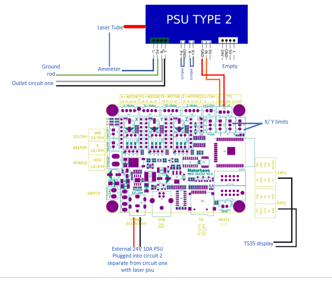
I have my unit wired as follows:
Mks pins S and TTL, to K40 white type 2 psu pins G and In.
My spindle minus is hooked to L
My unit for a very long time was working with only the in and g hooked up, but I was getting a wierd interference on my display… That went away when I conned to L to spindle -. Turns out that was ~200VDC peak leaking ftom inside the PSU somewhere.
I reproduced that issue with two type 2 Psu’s.
I will be adjusting frequencies tonight and seeing what happens.
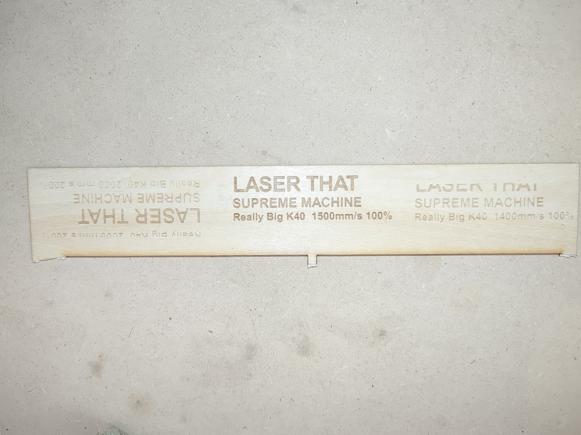
This all started when I maxed my laser out at 1000mm/s and 100%- or so I thought…
Manual override of power to 200% allows me to run at 2000mm/s.
2000 accel on x
.1% overscan…
It makes very nice 0.15" tall letters at that speed.
So I have taken a dive into a hell of a rabbit hole, of why S1000 does not equal true full pwm output.
I will be measuring voltages tonight as well., unfortunately someone at work stole the o-scope…
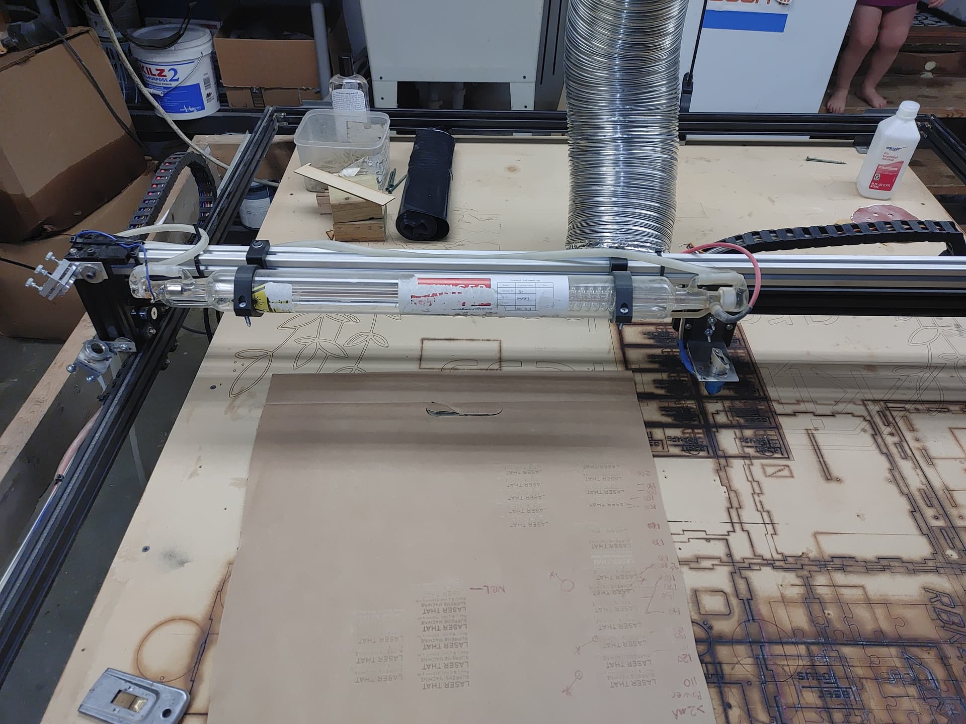
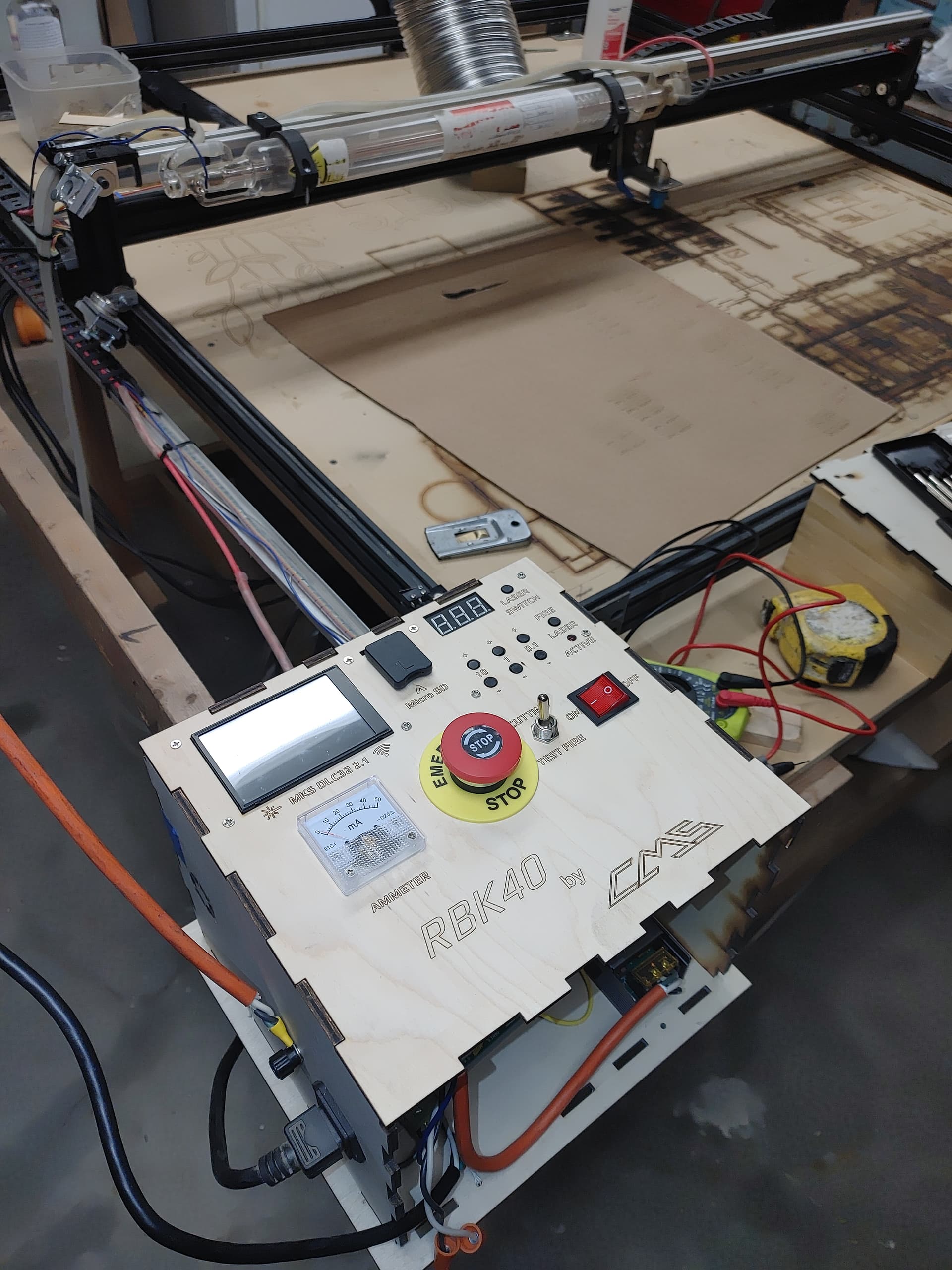
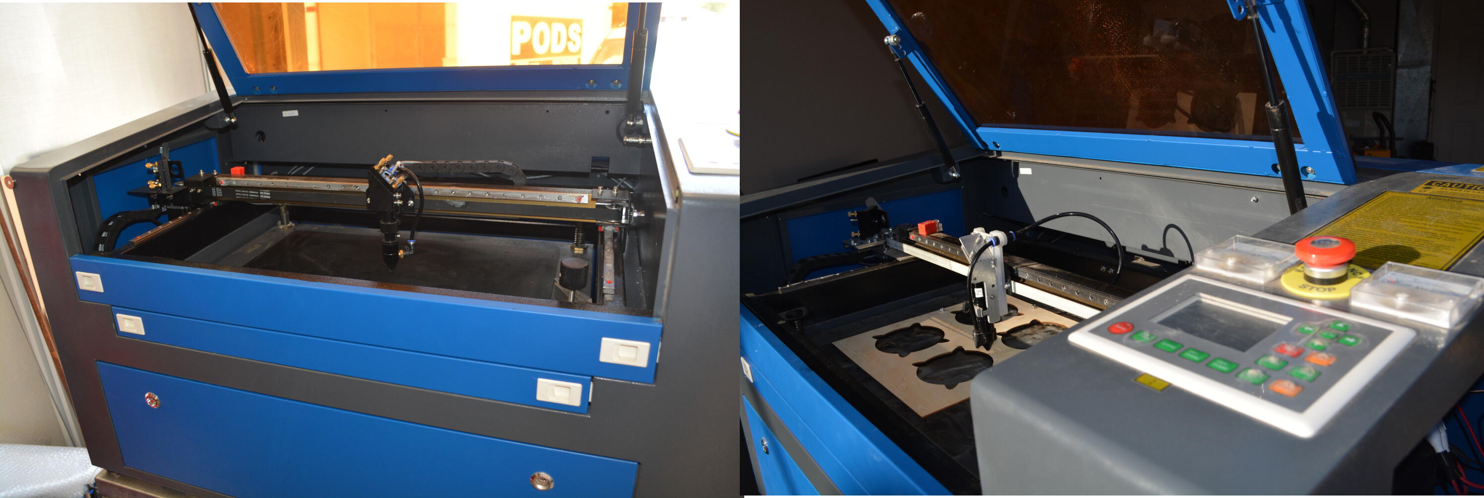
Quick background of my machine… It’s a universal engraver frame wiith the mks DLC32 v 2.1 running 2.3 latest firmware. I built the tube onto Tha gantry so as to minimize beam travel…
Now I need speed, because time is money. And if my machine can do double, but I have to manually set that with each job, then I need to do something different.
So yeah laser enable did nothing to prevent firing via pwm, but it made stray voltage leak through pwm line.
I have no inline potentiometer, have never used one, my machine came with the digital panel to set the power.
The pot inside the psu has been turned down to limit max laser power. I have kept it at 25mA. I do not care if I burn out this tube… I will upgrade. I have the cw 5000 chiller too.
The chiller input and the k+ k are just jumpered for now. I will be changing that with a relay, once I get firmware and controls sorted out
I know of few lasers that will run 1000mm/s… I’d like to see a photo of what your machine looks like to be able to pull that off. I find 2000mm/s unfathomable. Both of these will more than likely outrun your lps.
Convince us that it’s running this fast… I’m always open and they get faster… However I know what it took to get mine up to 1650mm/s and those speeds are useless except for academia.
I don’t know what manual override of power is… and how does it speed up the axes?
Is your controller configured to allow for these kinds of speeds?
I’ll happily give a full break down later.
Look at a universal engraver diode laser, then imagine a tube on an extra gantry beam…
And I will gladly post pictures and video as proof of my machine doing this stuff.
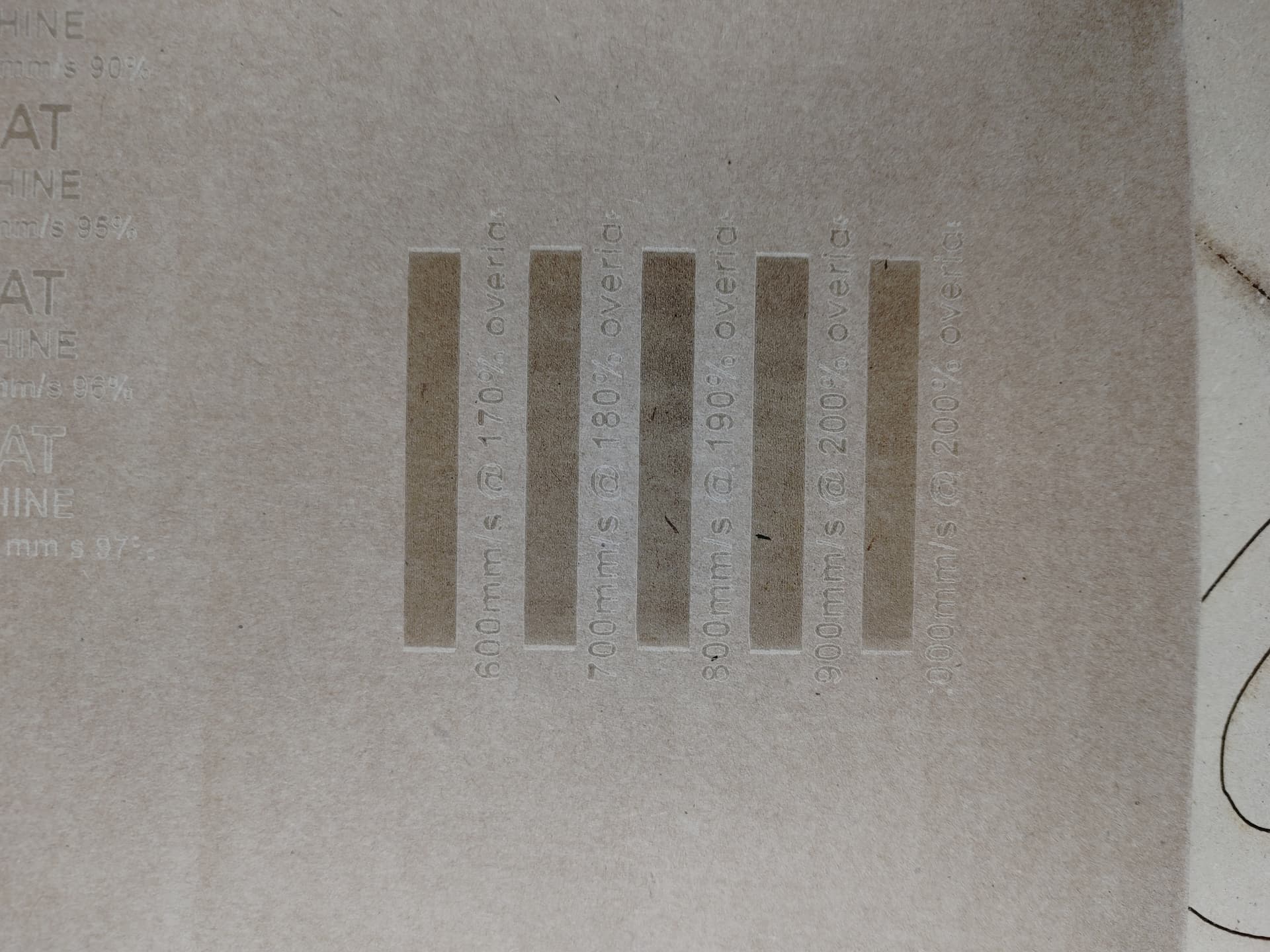
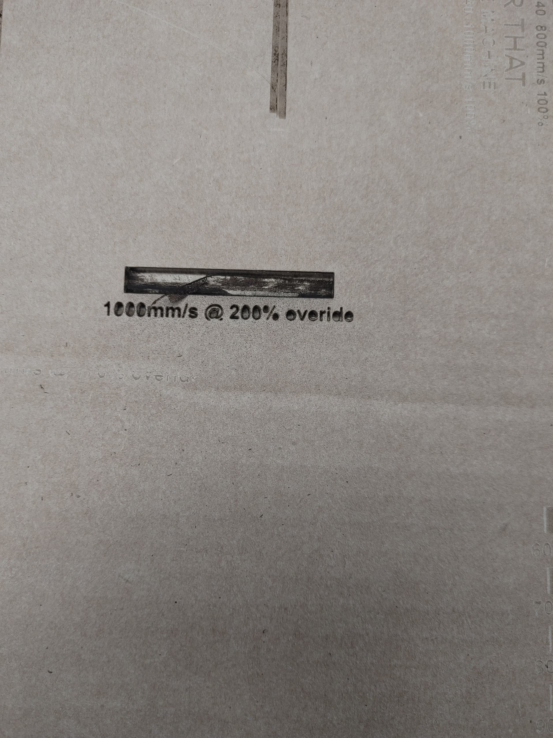
I have a large sheet of cardboard with alot of test cuts on it right now.
And yes, my max x is 6000, I will not go that fast. X is my scanning axis for engraving. I have dual y motors so that is set much slower because the gantry is relatively heavy.
I forget which stepper drivers I have rn. But this is far from a stock K40.
To answer your question, manual speed and power overrides are done via the ts35 touch screen. There is a menu to change it on the fly during jobs.
And the psu you have in your post is type 1. See K40.se
Its a good resource for the basics.
I mean, my controller is doing what I’m asking of it. Whter or not it truly is 2000mm/s… I’ll do a long run and time it.
And yeah I know 6 is rediculous. I just set it to some BS number higher than I intend to go.
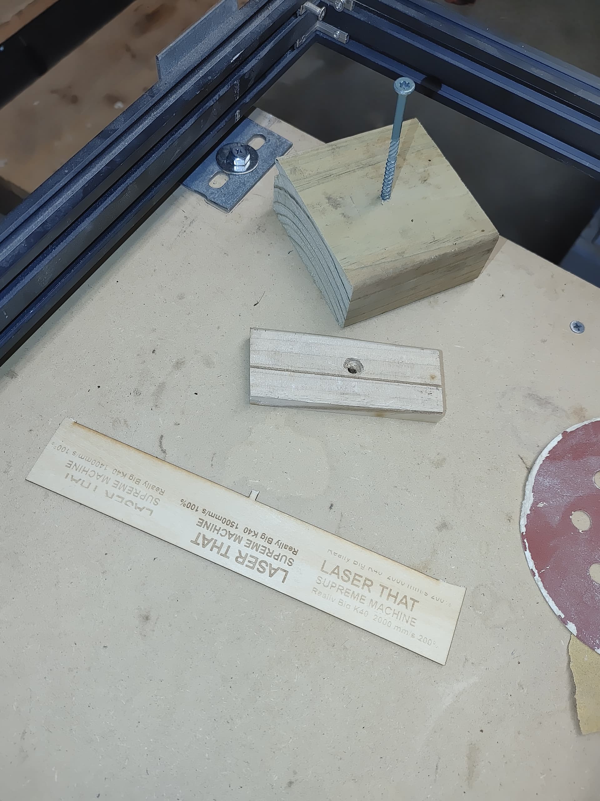
Don’t laugh, I just move the whole table up. I use pieces of wood the same thickness as what I’m working on to acheive desired Z height
Kept the gantry simple and light that way. Most of my jobs are varying thin birch plys.
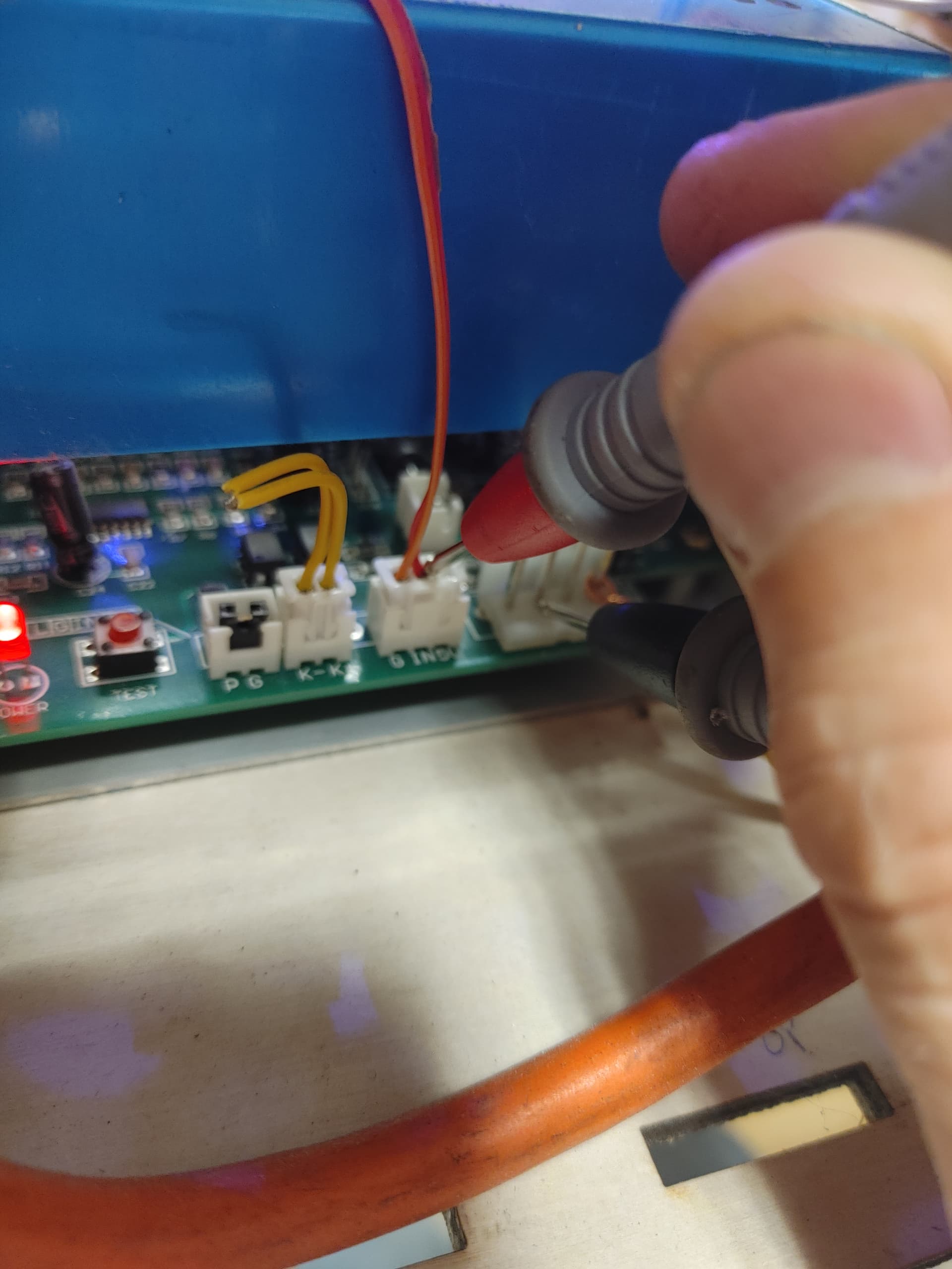
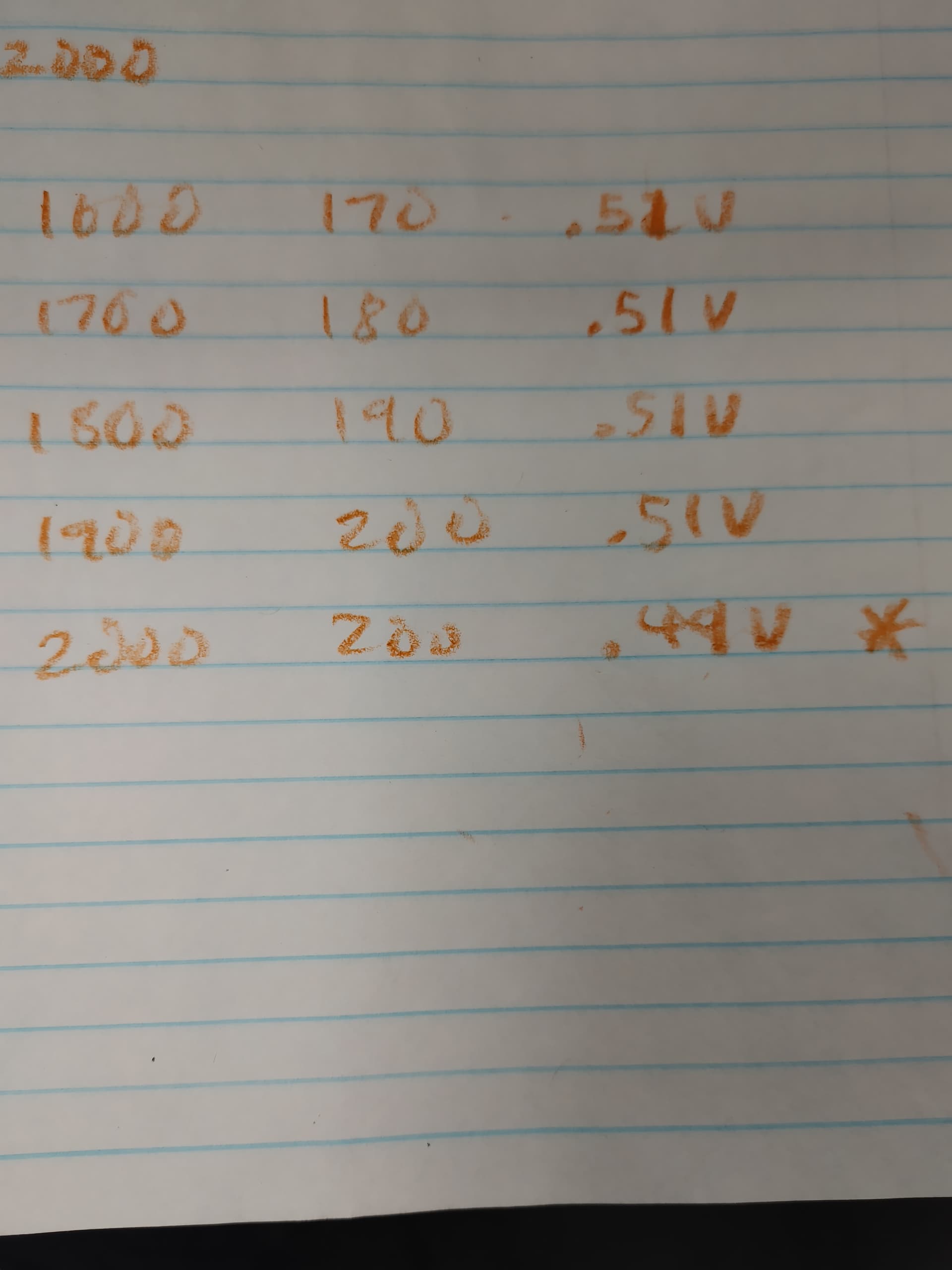
Now to comfirm some suspicion, I’m gonna run some solid fill long shapes to get voltage readings that aren’t too fast for my meter. Inital readings confirm 100% at 0.15v and 200% maxed at 0.3v
I know it’s not 5v but my multimeter may not be sensitive enough or taking fast enough readings.
And yet it only peak at 10ma on my ammeter.
My ammeter is right, because I know what true 100% full power looks like at slow slow speed when cutting, and it’s enough to go through this cardboard and into my table a ways.
I think it’s time for fluid NC, unless mks releases source code the 2.3 firmware…
OK, the L is not floating. There is a wire there, it’s not quite showing up, it is wrapped around the post to test. It lights up the red led on the mks.
It is power increase.
I measured the same spot for all tests…
Something is terribly wrong somewhere.
Its either my board, or I’m delving into speeds not messed with by K40 people because 1000 has been max of most.
19.9 volts is very bad for something expecting 5v Max.
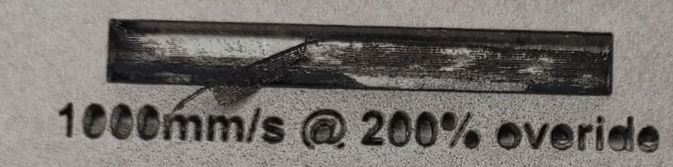
But it is making a nice clean text. … Somehow.
There is no trickery going on, those rectangles only showed 0.51 volts max…
I want to see someone else with a type 2 psu measure their voltage and see what it actually reads…
Im at a loss right now, it works like it is…
But not like I want.
I will do more tests at various speed levels,. Use proper connector, and attach spare leads to just leave the multimeter in place without holding it…
I’ll start off at 300mm/s and 37% which was making really nice business cards for me…
Looking like a tomorrow project…
It’s clean as in there is not shape distortion caused by erro in machine moves, the onky issue is the extreme power level…
Ill bust out the plywood for further testing